Advertisement
Quick Links
Advertisement

Related Manuals for Gibson Gold Tone GA-15RV


Summary of Contents for Gibson Gold Tone GA-15RV
- Page 3 GIBSON ‘GOLD TONE’ GA-15RV CIRCUIT DISCRIPTION Please refer to circuit diagram for DC voltages and other information INPUT SECTION AND PREAMP SK1 and SK3 are the LO and HI sensitivity inputs respectively. When the LO socket is used R5, R39 and R3 act as a potential divider to reduce the input level to the preamp.
-
Page 4: Power Stage
RV3 controls the level of the reverb. Across pins 1 and 2 is TR6, a J175 FET. When SK4 is shorted out, by a footswitch, TR6 is also effectively shorted which results in the reverb being turned off. The reverb signal is then mixed with the dry signal, via R58, before going into the phase splitter. - Page 5 The ac heater supply is simply connected via a twisted pair connecting lead to V3 and V4 after first going through the secondary fuses The 25.2V DC supply is highly regulated supply using a BD647 (TR7) as the main regulating device.
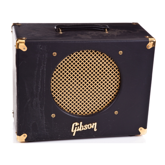
- Page 6 GIBSON ‘GOLDTONE’ GA-15RV The GA-15RV is part of the Gibson ‘GoldTone’ valve guitar amplifier range. It is a no nonsense, compact, purists valve guitar amplifier and has the minimum controls necessary to produce a good range of sounds, from clean to overdriven, into its single speaker.
-
Page 7: Pentode/Triode Switch
Unlike other single tone controls on other amplifiers, which act merely as a treble roll off, this control works in a different way. It is a dual gang potentiometer which controls two functions simultaneously. In the fully anti-clockwise position the midrange is dominant in the sound, turning the control clockwise decreases the mids while at the same time increasing the higher frequencies. -
Page 8: Technical Specifications
Before mains is applied to the unit, check that it is the correct voltage and make sure the POWER switch is in the OFF position. Connect power lead to mains outlet then switch to STANDBY and wait about a minute before switching to ON. This will ensure that the valves have time to warm up before large voltages are applied to the plates. - Page 9 C32-PCB-PC00064x3. GIBSON 15R ISSUE 3 14/2/97 PS Description Part Code Where Used PC00064 issue 1 RESISTORS 0 ohm link 72-RCZERO 1/4W 72-RM2R7 R80 R81 1/4W 72-RM10R R48 R49 1/4W 72-RM56R 1/4W 72-RM82R 1/4W 72-RM1K R27 R50 R51 R57 1/4W 72-RM1K2...
- Page 10 2N3906 72-T2N3906 TR1 TR2 J175 72-FET-J-175 BD647 72-TBD647 RC4558 72-IC-RC4558P IC1 IC2 CAPACITORS 500V ceramic 72-C47P-500VCD 100p 1KV ceramic 72-C100P-1KVCD 220p 1KV ceramic 72-C220P-1KVCD 470p 1KV ceramic 72-C470P-1KVCD 1KV ceramic 72-C1000P-1KVCD 1KV ceramic 72-C4700P-1KVCD C30 C31 C32 C33 100V axial 72-C33P-100VCA C41 C42 100p...
- Page 11 Large slide DPDT horiz 73-SWT-SLIDER-DP Mini Toggle SPDT vert 73-SWT-M-TGL-PCB POTENTIOMETERS 73-POT-A1M 250K LIN DUAL GANG 73-POT-B250K-DG 73-POT-50KB VALVE BASES B9A PCB valve base 73-VAL-SOCKET FUSE HOLDERS 72-FUS-HLD-PCB-2 FS1 FS2 FS3 FS4 TEST PIN 73-PIN-TERM TO220 HEAT SINK 71-HS-PF752 FLYING LEADS ETC Cathode heater lead C00-LEAD-VEL12- insert into HTR0, HTR1 &...
Need help?
Do you have a question about the Gold Tone GA-15RV and is the answer not in the manual?
Questions and answers