Table of Contents
Advertisement
WARRANTY REGISTRATION FORM
Unit Serial Number: _______________________________________
Customer Name:
Address:
Date of Purchase:
Purchased From:
Dealer Name:
Address:
IMPORTANT NOTE:
In order to receive the full five year product warranty, please mail this
completed form together with a copy of your sales receipt to Balanced Audio
Technology at the address below, within thirty days of purchase.
Failure to do so will result in the product being warrantied for one year
from the date of manufacture.
1300 First State Blvd. Suite A W ilmington, DE 19804
VK-P5
_______________________________________
_______________________________________
_______________________________________
_______________________________________
_______________________________________
_______________________________________
_______________________________________
Tel: 302-999-8855 Fax: 302-999-8818
Advertisement
Table of Contents

Related Manuals for Balanced Audio Technology VK-P5


Summary of Contents for Balanced Audio Technology VK-P5
-
Page 1: Warranty Registration Form
IMPORTANT NOTE: In order to receive the full five year product warranty, please mail this completed form together with a copy of your sales receipt to Balanced Audio Technology at the address below, within thirty days of purchase. Failure to do so will result in the product being warrantied for one year from the date of manufacture. - Page 2 VK-P5 Balanced Phono Stage Owner's Manual 1300 First State Blvd. Suite A W ilmington, DE 19804 Tel: 302-999-8855 Fax: 302-999-8818...
- Page 3 NOTE: Your VK-P5 Phono Preamplifier was preset at the factory to the following configuration: Gain: High Input Resistive Loading: Input Capacitive Loading: None Please refer to the chapter on configuration switch setting for information on optimizing the unit parameters.
-
Page 4: Package Contents
Introduction Thank you for your purchase of the Balanced Audio Technology VK-P5 balanced phono stage. Please read this owner's manual to obtain the full benefit of the VK-P5 in your system. It will provide you with the needed safety information and operating procedures for this exceptional unit. - Page 5 Do not stack the VK-P5 phono stage on top of other units, nor vice versa. General Description of VK-P5 Phono Preamplifier The VK-P5 balanced all-tube phono stage is designed to provide the maximum possible performance while operating in conjunction with the wide verity of phono cartridges available today.
-
Page 6: Description Of Controls
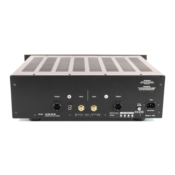
Output Connection The VK-P5 is equipped with XLR output connectors. Any high quality set of balanced interconnects can be used to connect the VK-P5 to your balanced preamplifier. Single-ended preamplifiers can be connected to the VK-P5 output through the use of XLR- to-RCA adapters, available from BAT. -
Page 7: Configuration Switches
Configuration Switches WARNINGS: Please make sure that the VK-P5 is turned OFF and your preamplifier is in MUTE before changing the state of any internal configuration switches in VK-P5. Hazardous voltages are present on the unit’s printed circuit board. DO NOT operate the VK-P5 with its top cover removed. - Page 8 Cartridge loading switches S101 and S201 Resistance: The 47K load resistor is permanently connected to the cartridge input. If a different loading value is desired, it can be obtained by switching in additional resistors, installed on the VK-P5 PC board. This is accomplished by using the two DIP switches, S101 and S201, which allow multiple choices for resistive and capacitive cartridge loading.
-
Page 9: Gain Switch
Gain Switch By moving the switch S2 from High to Low position, the amplifier’s gain is reduced by about 6dB. While the High gain position provides the most universal setting, it may be desired to reduce the overall system gain when using some high output phono cartridges. Gain Potentiometers Gain potentiometers R130 and R230 allow the user to optimize the VK-P5 performance when using very high output cartridges. -
Page 11: Fuse Protection
Factory supplied fuses should be only replaced with the same type and rating parts. Servicing The Balanced Audio Technology VK-P5 should require no service other than changing tubes to maintain its high performance. The vacuum tubes used in the VK-P5 are high quality 6922’s and 6SN7’s rated for approximately 5000 hours of use. - Page 12 Resistance: Selectable from 100 to 47k Capacitance: Selectable from 100pF to 1000pF Inputs: RCA Connectors Outputs: XLR Balanced (XLR-to-RCA adapters available) Tube Complement: 8 6922’s and 2 6SN7’s Power Consumption: 150 VA Max Dimensions: 19” (W) x 5.5” (H) x 14” (D) Weight: 35 lb.
- Page 13 If this product contains a materials, manufacturing, or workmanship defect that cannot be repaired at the dealership where the product was purchased, it must be packed in original packaging and returned to Balanced Audio Technology via insured freight, at the owners expense. If replacement packaging materials are required, they will be supplied by the factory at a nominal charge.
Need help?
Do you have a question about the VK-P5 and is the answer not in the manual?
Questions and answers