Table of Contents
Advertisement
Copyright
This publication, including all photographs, illustrations and software, is protected
under international copyright laws, with all rights reserved. Neither this manual, nor
any of the material contained herein, may be reproduced without written consent of
the author.
Version 1.0
Disclaimer
The information in this document is subject to change without notice. The manufac-
turer makes no representations or warranties with respect to the contents hereof and
specifically disclaims any implied warranties of merchantability or fitness for any
particular purpose. The manufacturer reserves the right to revise this publication and
to make changes from time to time in the content hereof without obligation of the
manufacturer to notify any person of such revision or changes.
Trademark Recognition
Microsoft, MS-DOS and Windows are registered trademarks of Microsoft Corp.
AMD, Phenom, Athlon, Sempron and Duron are registered trademarks of AMD
Corporation.
Other product names used in this manual are the properties of their respective
owners and are acknowledged.
Federal Communications Commission (FCC)
This equipment has been tested and found to comply with the limits for a Class B
digital device, pursuant to Part 15 of the FCC Rules. These limits are designed to
provide reasonable protection against harmful interference in a residential installa-
tion. This equipment generates, uses, and can radiate radio frequency energy and, if
not installed and used in accordance with the instructions, may cause harmful inter-
ference to radio communications. However, there is no guarantee that interference
will not occur in a particular installation. If this equipment does cause harmful
interference to radio or television reception, which can be determined by turning the
equipment off and on, the user is encouraged to try to correct the interference by one
or more of the following measures:
•
Reorient or relocate the receiving antenna.
•
Increase the separation between the equipment and the receiver.
•
Connect the equipment onto an outlet on a circuit different from that to
which the receiver is connected.
•
Consult the dealer or an experienced radio/TV technician for help.
Shielded interconnect cables and a shielded AC power cable must be employed with
this equipment to ensure compliance with the pertinent RF emission limits govern-
ing this device. Changes or modifications not expressly approved by the system ' s
manufacturer could void the user's authority to operate the equipment.
Preface
Preface
Advertisement
Table of Contents

Related Manuals for ECS A890GXM-A


Summary of Contents for ECS A890GXM-A
- Page 1 Preface Copyright This publication, including all photographs, illustrations and software, is protected under international copyright laws, with all rights reserved. Neither this manual, nor any of the material contained herein, may be reproduced without written consent of the author. Version 1.0 Disclaimer The information in this document is subject to change without notice.
-
Page 2: Declaration Of Conformity
Declaration of Conformity This device complies with part 15 of the FCC rules. Operation is subject to the following conditions: • This device may not cause harmful interference, and • This device must accept any interference received, including interfer- ence that may cause undesired operation. Canadian Department of Communications This class B digital apparatus meets all requirements of the Canadian Interference- causing Equipment Regulations. -
Page 3: Table Of Contents
T T T T T ABLE OF CONTENTS ABLE OF CONTENTS ABLE OF CONTENTS ABLE OF CONTENTS ABLE OF CONTENTS Preface Chapter 1 Introducing the Motherboard Introduction....................1 Features....................2 Motherboard Components..............4 Chapter 2 7 7 7 7 7 Installing the Motherboard Safety Precautions................7 Choosing a Computer Case..............7 Installing the Motherboard in a Case..........7... - Page 4 Load Default Settings..............42 Supervisor Password..............42 User Password................43 Save & Exit Setup ................43 Exit Without Saving................43 Updating the BIOS.................44 Chapter 4 45 45 45 45 Using the Motherboard Software About the Software DVD-ROM/CD-ROM........45 Auto-installing under Windows XP/Vista/7........45 Running Setup................46 Manual Installation................48 Utility Software Reference..............48 49 49 49 49...
-
Page 5: Introducing The Motherboard
Chapter 1 Introducing the Motherboard Introduction Thank you for choosing the A890GXM-A motherboard. This motherboard is a high performance, enhanced function motherboard that supports socket for AMD Phenom II/Athlon II/Sempron processors (socket AM3) for high-end business or personal desktop markets. The motherboard incorporates the AMD 890GX Northbridge (NB) and SB850 Southbridge (SB) chipsets. -
Page 6: Features
Feature Processor This motherboard uses a socket AM3 that carries the following features: • Accommodates AMD Phenom II/Athlon II/Sempron processors (socket AM3) • Supports HyperTransport (HT) 3.0 interface speeds HyperTransport Technology is a point-to-point link between two devices, it enables integrated circuits to exchange information at much higher speeds than currently available interconnect technologies. -
Page 7: Onboard Lan
Audio • 7.1+2 Channel High Definition Audio Codec • Meets Microsoft WLP3.x (Windows Logo Program) audio require- ments • All DACs supports 44.1k/48k/96k/192kHz sample rate • Software selectable 2.5V/3.2V/4.0V VREFOUT • Direct Sound 3D. compatible • Power Support: Digital: 3.3V; Analog: 5.0V Onboard LAN •... -
Page 8: Specifications
Specifications • AMD Phenom II/Athlon II/Sempron processors (socket AM3) • Supports “Hyper-Threading” technology CPU Chipset • NB: AMD 890GX SB: SB850 Memory • Dual-channel DDR3 memory architecture • 4 x 240-pin DDR3 DIMM sockets support up to 32 GB • Supports DDR3 1600 (OC)/1333/1066/800 DDR3 SDRAM... -
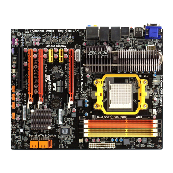
Page 9: Motherboard Components
Motherboard Components The above image is for reference only; please take the actual motherboard for detailed parts. Introducing the Motherboard... - Page 10 Table of Motherboard Components LABEL CO MPO N EN TS 1. CPU Socket Socket for AMD Phenom II processor (socket AM3) 2. CPU_FAN CPU cooling fan connector 3. DDR3_1~4 240-pin DDR3 SDRAM slots 4. ATX_POW ER Standard 24-pin ATX power connector 5.
-
Page 11: Installing The Motherboard
Chapter 2 Installing the Motherboard Safety Precautions • Follow these safety precautions when installing the motherboard • Wear a grounding strap attached to a grounded device to avoid dam- age from static electricity • Discharge static electricity by touching the metal case of a safely grounded object before working on the motherboard •... -
Page 12: Installing Hardware
Do not over-tighten the screws as this can stress the motherboard. Installing Hardware Installing the Processor Caution: When installing a CPU heatsink and cooling fan make sure that you DO NOT scratch the motherboard or any of the surface-mount resis- tors with the clip of the cooling fan. - Page 13 Before installing the Processor This motherboard automatically determines the CPU clock frequency and system bus frequency for the processor. You may be able to change these settings by making changes to jumpers on the motherboard, or changing the settings in the system Setup Utility.
-
Page 14: Installing Memory Modules
CPU Installation Procedure The following illustration shows CPU installation components. Install your CPU. Pull up the lever away from the socket and lift up to 90-degree angle. Locate the CPU cut edge (the corner with the pin hold noticeably missing). Align and insert the CPU correctly. -
Page 15: Installation Procedure
Installation Procedure Refer to the following to install the memory modules. This motherboard supports unbuffered DDR3 SDRAM only. Push the latches on each side of the DIMM slot down. Align the memory module with the slot. The DIMM slots are keyed with notches and the DIMMs are keyed with cutouts so that they can only be installed correctly. - Page 16 Table A: DDR3 (memory module) QVL (Qualified Vendor List) The following DDR3 memory modules have been tested and qualified for use with this motherboard. Type Size Vendor Module Name Hynix HMT112U6AFP8C-G7N0 AA Kingston KVR1066D3N7 1 GB Micron MT8JTF12864AZ-1G1F1 Ramaxel RMR1810NA48E7F-1066-LF M2Y2G64CB8HC9N-BE Elixir M2Y2G64CB8HC5N-BE...
- Page 17 Table B: DDR3 (memory module) QVL (Qualified Vendor List) The following DDR3 memory modules have been tested and qualified for use with this motherboard. Vendor Module Name Type Size A-data AD3U1333B2G9-B Apacer 78.A1GC6.9L1 M2F2G64CB8HA4N-CG 0903.TW M2Y2G64CB8HC9N-CG Elixir EBJ21UE8BDF0-DJ-F/J1108BDSE-DJ-F M2Y2G64CB8HA9N-CG 0920.TW F3-10666CL9D-4GBRL G.SKILL F3-10666CL8D-4GBECO...
-
Page 18: Expansion Slots
Expansion Slots Installing Add-on Cards The slots on this motherboard are designed to hold expansion cards and connect them to the system bus. Expansion slots are a means of adding or enhancing the motherboard’s features and capabilities. With these efficient facilities, you can in- crease the motherboard’s capabilities by adding hardware that performs tasks that are not part of the basic system. - Page 19 Follow these instructions to install an add-on card: Remove a blanking plate from the system case corresponding to the slot you are going to use. Install the edge connector of the add-on card into the expansion slot. Ensure that the edge connector is correctly seated in the slot. Secure the metal bracket of the card to the system case with a screw.
-
Page 20: Connecting Optional Devices
Connecting Optional Devices Refer to the following for information on connecting the motherboard’s optional devices: SATA1~5: Serial ATA connectors These connectors are used to support the new Serial ATA devices for the highest data transfer rates (6.0 Gb/s), simpler disk drive cabling and easier PC assembly. It elimi- nates limitations of the current Parallel ATA interface. - Page 21 F_USB1~4: Front Panel USB headers The motherboard has six USB ports installed on the rear edge I/O port array. Addi- tionally, some computer cases have USB ports at the front of the case. If you have this kind of case, use auxiliary USB connector to connect the front-mounted ports to the motherboard.
-
Page 22: Installing A Sata Hard Drive
Installing a SATA Hard Drive This section describes how to install a SATA hard drive. About SATA Connectors Your motherboard features five SATA connectors supporting a total of four drives. SATA refers to Serial ATA (Advanced Technology Attachment) is the standard inter- face for the IDE hard drives which are currently used in most PCs. -
Page 23: Connecting I/O Devices
Connecting I/O Devices The backplane of the motherboard has the following I/O ports: VGA Port Connect your monitor to the VGA port. DVI Port Use the DVI port to connect the monitor. DIS Port(Dispaly Use the Display port to connect the monitor. Port) HDMI Port Connect the HDMI port to the HDMI devices. -
Page 24: Connecting Case Components
Connecting Case Components After you have installed the motherboard into a case, you can begin connecting the motherboard components. Refer to the following: Connect the CPU cooling fan cable to CPU_FAN. Connect the standard power supply connector to ATX_POWER. Connect the case speaker cable to SPK. Connect the case switches and indicator LEDs to the PANEL. - Page 25 Connecting 8/4-pin power cable Users please note that the 8-pin and 4-pin power cables can both be con- nected to the ATX12V connector. When installing 8-pin power cable, the latches of power cable and the ATX12V connector match perfectly. 8-pin power cable When installing 4-pin power cable, the latch falls on the left side of the ATX12V connector.
- Page 26 SYS_FAN: FAN Power Connector Signal Name Function System Ground Power +12V +12V Sense Sensor SPK: Internal speaker Signal Name Signal ATX12V: ATX 12V Power Connector Signal Name Signal Name Ground +12V Ground +12V Ground +12V Ground +12V ATX4P: Auxliary Power Connector for Graphics Interface. Signal Name +12V Installing the Motherboard...
-
Page 27: Front Panel Header
Front Panel Header The front panel header (F_PANEL) provides a standard set of switch and LED headers commonly found on ATX or Micro ATX cases. Refer to the table below for information: Signal Function Signal Function HD_LED_P Hard disk LED (+) 2 FP PWR/SLP *MSG LED (+) HD_LED_N Hard disk LED (-) FP PWR/SLP *MSG LED (-) - Page 28 Memo Installing the Motherboard...
-
Page 29: Using Bios
Chapter 3 Using BIOS About the Setup Utility The computer uses the latest “American Megatrends Inc. ” BIOS with support for Windows Plug and Play. The CMOS chip on the motherboard contains the ROM setup instructions for configuring the motherboard BIOS. The BIOS (Basic Input and Output System) Setup Utility displays the system ’... -
Page 30: Resetting The Default Cmos Values
Press the delete key to access the BIOS Setup Utility. CMOS Setup Utility -- Copyright (C) 1985-2005, American Megatrends, Inc. Standard CMOS Setup M.I.B. III (MB Intelligent BIOS III) Advanced Setup Load Default Settings Advanced Chipset Setup Supervisor Password Integrated Peripherals User Password Power Management Setup Save &... -
Page 31: Using Bios
Using BIOS When you start the Setup Utility, the main menu appears. The main menu of the Setup Utility displays a list of the options that are available. A highlight indicates which option is currently selected. Use the cursor arrow keys to move the highlight to other options. -
Page 32: Standard Cmos Setup
For the purpose of better product maintenance, the manufacture reserves the right to change the BIOS items presented in this manual. The BIOS setup screens shown in this chapter are for reference only and may differ from the actual BIOS. Please visit the manufacture’s website for updated manual. - Page 33 Type (Auto) Use this item to configure the type of the IDE device that you specify. If the feature is enabled, it will enhance hard disk performance by reading or writing more data during each transfer. LBA/Large Mode (Auto) Use this item to set the LBA/Large mode to enhance hard disk performance by optimizing the area the hard disk is visited each time.
-
Page 34: Advanced Setup
1st Boot Device Hard Drive 2nd Boot Device CD/DVD 3rd Boot Device Removable Dev. Hard Disk Drivers Press Enter Boot Other Device ECS eJIFFY Function Disabled : Move Enter : Select +/-/: Value F10: Save ESC: Exit F1:General Help F9: Optimized Defaults AMD C&Q (Auto) - Page 35 ECS eJIFFY Function (Disabled) Use this item to enable or disable the ECS eJIFFY Function. eJIFFY is ECS unique software program for the quick access to the internet without entering O.S. Please refer to Chapter 6 to know more about eJIFFY.
-
Page 36: Advanced Chipset Setup
Advanced Chipset Setup This page sets up more advanced information about your system. Handle this page with caution. Any changes can affect the operation of your computer. CMOS Setup Utility - Copyright (C) 1985-2005, American Megatrends, Inc. Advanced Chipset Setup Help Item Internal Graphics Mode UMA+SIDEPORT... -
Page 37: Integrated Peripherals
Integrated Peripherals This page sets up some parameters for peripheral devices connected to the system. CMOS Setup Utility - Copyright (C) 1985-2005, American Megatrends, Inc. Integrated Peripherals Help Item Onboard SATA Mode Enabled SATA Configuration Options SATA 6.0 Gbps Support Enabled Onboard AUDIO Function Enabled... -
Page 38: Power Management Setup
Power Management Setup This page sets up some parameters for system power management operation. CMOS Setup Utility - Copyright (C) 1985-2005, American Megatrends, Inc. Power Management Setup Help Item ACPI Suspend Type PWRON After PWR-Fail Power Off Select the ACPI Resume By PCI/PCI-E/Lan PME Disabled state used for... -
Page 39: Pci/Pnp Setup
PCI / PnP Setup This page sets up some parameters for devices installed on the PCI bus and those utilizing the system plug and play capability. CMOS Setup Utility - Copyright (C) 1985-2005, American Megatrends, Inc. PCI / PnP Setup Help Item Allocate IRQ to PCI VGA YES: Assigns IRQ to... - Page 40 Smart Fan Function Scroll to this item and press <Enter> to view the following screen: CMOS Setup Utility - Copyright (C) 1985-2005, American Megatrends, Inc. Smart Fan Function Help Item SMART FAN Control Enabled SMART Fan Mode Normal Disabled SMART Fan start PWM value Enabled SMART Fan start TEMP.(°C) DeltaT1...
- Page 41 CMOS Setup Utility - Copyright (C) 1985-2005, American Megatrends, Inc. Smart Fan Function Help Item SMART FAN Control Enabled Normal: auto adjusts de- SMART Fan Mode Normal pending on the CPU SMART Fan start PWM value temperture SMART Fan start TEMP.(°C) DeltaT1 Quiet: auto minimizes fan SMART Fan Slope PWM value...
- Page 42 System Component Characteristics These items display the monitoring of the overall inboard hardware health events, such as System & CPU temperature, CPU & DIMM voltage, CPU & system fan speed,...etc. • CPU Temperature • NB Temperature • CPU FAN Speed •...
-
Page 43: Mb Intelligent Bios)
M.I.B. III (MB Intelligent BIOS III) This page enables you to set the clock speed and system bus for your system. The clock speed and system bus are determined by the kind of processor you have in- stalled in your system. CMOS Setup Utility - Copyright (C) 1985-2005, American Megatrends, Inc. - Page 44 Bank Interleaving (Auto) This item is used to set the bank interleaving. Channel Interleaving (XOR of Address bits) This item is used to set the channel interleaving. Memory CLK (N/A, 667MHz) This item is used to set the memory clock mode. CAS Latency (Tcl) (N/A, 9Clk) This item controls the timing delay (inclockcycles) before the DRAM starts a read command after receiving it.
- Page 45 NB Voltage (Disabled) This item allows user to adjust NB voltage when enabled. HT Voltage (Disabled) This item allows user to adjust HT voltage when enabled. SB Voltage (Disabled) This item allows user to adjust SB voltage when enabled. SIDEPORT Voltage (1.5V) This item allows user to adjust sideport voltage when enabled.
-
Page 46: Load Default Settings
Load Default Settings This option opens a dialog box to ask if you are sure to install optimized defaults or not. You select [OK], and then press <Enter>, the Setup Utility loads all default values; or select [Cancel], and then press <Enter>, the Setup Utility does not load default values. -
Page 47: User Password
User Password This page helps you install or change a password. CMOS Setup Utility - Copyright (C) 1985-2005, American Megatrends, Inc. User Password User Password : Not Installed Help item : Move Enter : Select +/-/: Value F10: Save ESC: Exit F1:General Help F9: Optimized Defaults User Password (Not Installed) -
Page 48: Updating The Bios
Updating the BIOS You can download and install updated BIOS for this motherboard from the manufacturer’s Web site. New BIOS provides support for new peripherals, improve- ments in performance, or fixes for known bugs. Install new BIOS as follows: If your motherboard has a BIOS protection jumper, change the setting to allow BIOS flashing. -
Page 49: Using The Motherboard Software
Chapter 4 Using the Motherboard Software About the Software DVD-ROM/CD-ROM The support software DVD-ROM/CD-ROM that is included in the motherboard package contains all the drivers and utility programs needed to properly run the bundled products. Below you can find a brief description of each software program, and the location for your motherboard version. -
Page 50: Running Setup
Drivers Click the Setup button to run the software installation program. Setup Select from the menu which software you want to install. Browse CD The Browse CD button is the standard Windows command that allows you to open Windows Explorer and show the contents of the support disk. - Page 51 Click Next. The following screen appears: Check the box next to the items you want to install. The default options are recom- mended. Click Next run the Installation Wizard. An item installation screen appears: Follow the instructions on the screen to install the items. Drivers and software are automatically installed in sequence.
-
Page 52: Manual Installation
Windows Vista/7 will appear below UAC (User Account Control) message after the system restart. You must select “Allow” to install the next driver. Continue this process to complete the drivers installation. Manual Installation Insert the disk in the DVD-ROM/CD-ROM drive and locate the PATH.DOC file in the root directory. -
Page 53: Setting Up Amd Sb850 Raid Configuration
Chapter 5 Setting Up AMD SB850 RAID Configuration Setting Up a bootable RAID Array This section explains how to configure a bootable AMD RAID array. Setting Up the BIOS Start your computer, then press Delete to enter the BIOS setup. The BIOS CMOS Setup Utility screen appears. - Page 54 Press F10 to save the configuration and exit. The PC reboots. Enter the RAID BIOS Setup by pressing Ctrl-F when prompted, and proceed to set up the AMD RAID BIOS as described in the next section. Configuring the AMD RAID BIOS The AMD RAID BIOS set up lets you choose the RAID type and which hard drives you want to make part of the array.
- Page 55 Select [2], then select LD 1 in the following page. The Define LD Menu screen appears (Figure 1.4). Figure 1.4 Define LD Menu Using the Define a New Array Screen If necessary, press the tab key to move from field to field until the appropriate field is highlighted.
- Page 56 Assigning the Disks 1. Select the Assignment to Y to designate a free disk to be used as a RAID array disk. Figure 1.5 illustrates the Define a New Array screen after two disks have been assigned as RAID 0 array disks. Figure 1.5 FastBuild Utility—Array Disks Assigned 2.
- Page 57 Press ESC to exit. The Main Menu screen appears (Figure 1.7). Figure 1.7 Main Menu Press Y to reboot. The following screen appears (Figure 1.8). Figure 1.8 AMD RAID Configuration...
- Page 58 Installing the RAID Drivers Your system may come with a Windows install CD that already includes AMD RAID drivers. If so, then this section is not relevant. If that is not the case (or you are trying to install a new version of Windows), then you will need an AMD RAID driver F6 install floppy.
- Page 59 The following Windows Setup screen appears: Figure 1.11 Windows Setup—Selected SCSI Adapter Select “ATI AHCI Compatible RAID Controller-x86 platform” and press Enter for 32-bit OS or Select “ATI AHCI Compatible RAID Controller-x64 platform” and press Enter for 64-bit OS. The following Windows Setup screen appears listing both drivers:. Figure 1.12 Windows Setup—AMD drives listed Press Enter to continue with Windows XP Installation.
- Page 60 Memo AMD RAID Configuration...
-
Page 61: Setting Up Ejiffy Introduction
Note: eJIFFY is ECS optional feature utility corresponding to the DVD activation and BIOS setup. Please check the hard copy user’s guide or product color-box to see if the model has embodded eJIFFY feature. -
Page 62: Installation And Bios Setup
DVD Activation Finish the DVD utility setup, and then set the BIOS to complete eJIFFY activation. 1. Insert ECS software utility DVD and enter below “Utilities” screen. Click eJIFFY feature item to install. 2. Follow the onscreen instructions to finish eJIFFY setup. - Page 63 3. After setting up eJIFFY under Windows, you can switch eJIFFY display/keyboard language from English to your local language. The changes will be applied after rebooting. Note: The keyboard language selection list offers several more regional keyboard setups to switch with the default English typing. Please refer to the usage FAQ for more tips.
- Page 64 Setup button on the post screen to enter the BIOS setup page after boot up. 5. And then enter the Advanced Setup page to enable the item ECS eJIFFY Func- tion. Press F10 to save the configuration and exit. Restart your computer.
-
Page 65: Entering Ejiffy
Entering eJIFFY The post screen appears within several seconds after boot up and it has three buttons on it, Operating system, eJIFFY and BIOS Setup. Click to enter the normal OS you have installed such as Windows. Click to enter eJIFFY OS. Click to set the BIOS. -
Page 66: Features Icons
Feature Icons The following illustration shows the main feature icons that eJIFFY provides on the menu. eWeb: Firefox for web browsing/webmail and watching flash video. ePix: Photo viewing. ePal: On-line chat tool to use the most popular IMs in the world. (MSN, ICQ , AIM, etc.) Shows ePal on-line connection status. -
Page 67: Usage Faq
Usage FAQ Language Control Panel: Besides setting English as the default interface, eJIFFY offers multi-language displays and keyboard settings for language- switch. Open the language control panel to select a preferable language setting. Keyboard Language Setup Step1. Click to open the language control panel. Step 2: Click “Keyboard Language”... - Page 68 Click to enable all possible language inputs you want to apply, and click “Apply”: Move your mouse pointer on the text box and press Ctrl+Space. The language bar will then appear as fol- lows. Click the language bar here. Select your desired language Setting Up eJIFFY...
- Page 69 How to change display language? Open the Language Control Panel and click to show the display language list. Check your desired display language. Your selected display language will be applied after rebooting. Note: Details about eJIFFY please refer to eJIFFY in disk. Setting Up eJIFFY...
- Page 70 Memo Setting Up eJIFFY...
-
Page 71: Trouble Shooting
Chapter 7 Trouble Shooting Start up problems during assembly After assembling the PC for the first time you may experience some start up problems. Before calling for technical support or returning for warranty, this chapter may help to address some of the common questions using some basic troubleshooting tips. -
Page 72: Start Up Problems After Prolong Use
c) The PC suddenly shuts down while booting up. 1. The CPU may experience overheating so it will shutdown to protect itself. Ensure the CPU fan is working properly. 2. From the BIOS setting, try to disable the Smartfan function to let the fan run at default speed. - Page 74 Memo Trouble Shooting...
Need help?
Do you have a question about the A890GXM-A and is the answer not in the manual?
Questions and answers