ASROCK Q77M vPro User Manual
Hide thumbs
Also See for Q77M vPro:
- Quick installation manual (226 pages) ,
- Installation and configuration manual (11 pages)

Related Manuals for ASROCK Q77M vPro


Summary of Contents for ASROCK Q77M vPro
-
Page 1: User Manual
Q77M vPro User Manual Version 1.0 Published March 2012 Copyright©2012 ASRock INC. All rights reserved. -
Page 2: Copyright Notice
ASRock. ASRock assumes no responsibility for any errors or omissions that may appear in this manual. With respect to the contents of this manual, ASRock does not provide warranty of any kind, either expressed or implied, including but not limited to the implied warran- ties or conditions of merchantability or fitness for a particular purpose. -
Page 3: Table Of Contents
Quad CrossFireX Operation Guide 22 2.8 Dual Monitor and Surround Display Features ....26 2.9 ASRock Smart Remote Installation Guide ..... 29 2.10 Jumpers Setup ............... 31 2.11 Onboard Headers and Connectors ........ 32 2.12 Serial ATA (SATA) / Serial ATA2 (SATA2) Hard Disks Installation .............. - Page 4 3 UEFI SETUP UTILITY ..........45 3.1 Introduction ..............45 3.1.1 UEFI Menu Bar ............ 45 3.1.2 Navigation Keys ........... 46 3.2 Main Screen ..............46 3.3 OC Tweaker Screen ............47 3.4 Advanced Screen ............51 3.4.1 CPU Configuration ..........52 3.4.2 North Bridge Configuration........
-
Page 5: Introduction
In case any modifications of this manual occur, the updated version will be available on ASRock website without further notice. You may find the latest VGA cards and CPU support lists on ASRock website as well. ASRock website http://www.asrock.com If you require technical support related to this motherboard, please visit our website for specific information about the model you are using. -
Page 6: Specifications
1.2 Specifications Platform - Micro ATX Form Factor: 9.6-in x 9.6-in, 24.4 cm x 24.4 cm - All Solid Capacitor design ® - Supports 3 and 2 Generation Intel Core i7 / i5 / i3 in LGA1155 Package - 4 + 2 Power Phase Design ®... - Page 7 ® Pixel Shader 4.1, DirectX 10.1 with Intel Sandy Bridge CPU - Max. shared memory 1760MB (see CAUTION 9) - Three VGA Output options: D-Sub, DVI-D and DisplayPort (see CAUTION 10) - Supports DVI with max. resolution up to 1920x1200 @ 60Hz - Supports D-Sub with max.
- Page 8 - Drivers, Utilities, AntiVirus Software (Trial Version), CyberLink MediaEspresso 6.5 Trial, ASRock MAGIX Multimedia Suite - OEM Unique Feature - ASRock Extreme Tuning Utility (AXTU) (see CAUTION 11) - ASRock Instant Boot - ASRock Instant Flash (see CAUTION 12) - ASRock APP Charger (see CAUTION 13)
- Page 9 - FCC, CE, WHQL - ErP/EuP Ready (ErP/EuP ready power supply is required) (see CAUTION 24) * For detailed product information, please visit our website: http://www.asrock.com WARNING Please realize that there is a certain risk involved with overclocking, including adjusting the setting in the BIOS, applying Untied Overclocking Technology, or using third-party overclocking tools.
- Page 10 ® Vista / XP. For Windows OS with 64-bit CPU, there is no such limita- tion. You can use ASRock XFast RAM to utilize the memory that Win- ® dows cannot use. Only PCIE1 slot supports Gen 3 speed. To run the PCI Express in Gen 3 speed, please install an Ivy Bridge CPU.
- Page 11 17. ASRock XFast RAM is a new function that is included into ASRock Ex- treme Tuning Utility (AXTU). It fully utilizes the memory space that cannot ®...
- Page 12 CPU cooler types, Socket LGA 775, LGA 1155 and LGA 1156. Please be noticed that not all the 775 and 1156 CPU Fan can be used. ® ® 23. ASRock XFast RAM is not supported by Microsoft Windows XP / XP ®...
-
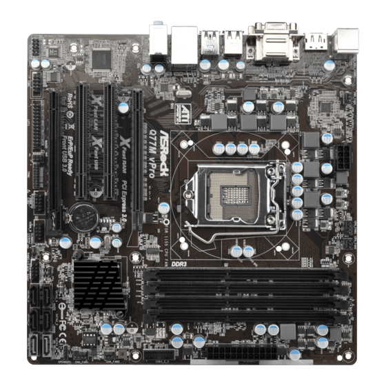
Page 13: Motherboard Layout
1.3 Motherboard Layout Power Fan Connector (PWR_FAN1) SATA2 Connector (SATA2_3, Black) ATX 12V Power Connector (ATX12V1) SATA2 Connector (SATA2_5, Black) 1155-Pin CPU Socket Power LED Header (PLED1) CPU Fan Connector (CPU_FAN1) System Panel Header (PANEL1, Black) CPU Fan Connector (CPU_FAN2) Clear CMOS Jumper (CLRCMOS1) 2 x 240-pin DDR3 DIMM Slots USB 2.0 Header (USB8_9, Black) -
Page 14: I/O Panel
1.4 I/O Panel USB 2.0 Ports (USB01) USB 2.0 Ports (USB_45) D-Sub Port (VGA1) USB 3.0 Ports (USB3_0_1) LAN RJ-45 Port USB 2.0 Ports (USB2_3) Line In (Light Blue) DVI-D Port (DVI1) ** 5 Front Speaker (Lime) DisplayPort (DISPLAY1) Microphone (Pink) PS/2 Keyboard Port (Purple) * There are two LEDs next to the LAN port. -
Page 15: Installation
Chapter 2: Installation This is a Micro ATX form factor (9.6" x 9.6", 24.4 x 24.4 cm) motherboard. Before you install the motherboard, study the configuration of your chassis to ensure that the motherboard fits into it. Make sure to unplug the power cord before installing or removing the motherboard. -
Page 16: Cpu Installation
2.3 CPU Installation For the installation of Intel 1155-Pin CPU, please follow the steps below. 1155-Pin Socket Overview Before you insert the 1155-Pin CPU into the socket, please check if the CPU surface is unclean or if there are any bent pins in the socket. Do not force to insert the CPU into the socket if above situation is found. - Page 17 Step 3. Insert the 1155-Pin CPU: Step 3-1. Hold the CPU by the edge which is marked with a black line. Step 3-2. Orient the CPU with the IHS (Inte- grated Heat Sink) up. Locate Pin1 and the two orientation key notches. orientation key notch alignment key Pin1...
-
Page 18: Installation Of Cpu Fan And Heatsink
2.4 Installation of CPU Fan and Heatsink This motherboard is equipped with 1155-Pin socket that supports Intel 1155-Pin CPUs. Please adopt the type of heatsink and cooling fan compliant with Intel 1155- Pin CPU to dissipate heat. Before you install the heatsink, you need to spray ther- mal interface material between the CPU and the heatsink to improve heat dissipa- tion. -
Page 19: Installation Of Memory Modules (Dimm)
2.5 Installation of Memory Modules (DIMM) This motherboard provides four 240-pin DDR3 (Double Data Rate 3) DIMM slots, and supports Dual Channel Memory Technology. For dual channel config- uration, you always need to install identical (the same brand, speed, size and chip-type) DDR3 DIMM pair in the slots: You have to install identical DDR3 DIMMs in Dual Channel A (DDR3_A1 and DDR3_B1;... -
Page 20: Installing A Dimm
Installing a DIMM Please make sure to disconnect the power supply before adding or removing DIMMs or system components. Step 1. Unlock a DIMM slot by pressing the retaining clips outward. Step 2. Align a DIMM on the slot such that the notch on the DIMM matches the break on the slot. -
Page 21: Expansion Slots (Pci And Pci Express Slots)
2.6 Expansion Slots (PCI and PCI Express Slots) There are 2 PCI slots and 2 PCI Express slots on this motherboard. PCI slots: PCI slots are used to install expansion cards that have the 32-bit PCI interface. PCIE slots:PCIE1 (PCIE 3.0 x16 slot) is used for PCI Express x16 lane width graphics cards, or used to install PCI Express graphics cards to support CrossFireX PCIE2 (PCIE 2.0 x16 slot) is used for PCI Express x4 lane width graph-... -
Page 22: Crossfirex Tm Operation Guide
2.7 CrossFireX and Quad CrossFireX Operation Guide This motherboard supports CrossFireX and Quad CrossFireX . CrossFireX technology offers the most advantageous means available of combining multiple high performance Graphics Processing Units (GPU) in a single PC. Combining a range of different operating modes with intelligent software design and an innovative interconnect mechanism, CrossFireX enables the highest possible level of performance and image quality in any 3D application. - Page 23 Step 2. Connect two Radeon graphics cards by installing a CrossFire Bridge on the CrossFire Bridge Interconnects on the top of the Radeon graphics cards. (The CrossFire Bridge is provided with the graphics card you pur- chase, not bundled with this motherboard. Please refer to your graphics card vendor for details.) CrossFire Bridge Step 3.
-
Page 24: Driver Installation And Setup
2.7.2 Driver Installation and Setup Step 1. Power on your computer and boot into OS. Step 2. Remove the AMD drivers if you have any VGA drivers installed in your system. The Catalyst Uninstaller is an optional download. We recommend using this utility to uninstall any previously installed Catalyst drivers prior to installation. - Page 25 Although you have selected the option “Enable CrossFire ”, the CrossFireX function may not work actually. Your computer will automatically reboot. After restarting your computer, please confirm whether the option “Enable CrossFire ” in “AMD Catalyst Control Center” is selected or not; if not, please select it again, and then you are able to enjoy the benefits of CrossFireX Step 7.
-
Page 26: Dual Monitor And Surround Display Features
2.8 Dual Monitor and Surround Display Features Dual Monitor Feature This motherboard supports dual monitor feature. With the internal VGA output support (DVI-D, D-Sub and DisplayPort), you can easily enjoy the benefits of dual monitor feature without installing any add-on VGA cards to this motherboard. This motherboard also provides independent display controllers for DVI-D, D-Sub and DisplayPort to support dual VGA output so that DVI-D, D-Sub and DisplayPort can drive the same or different display contents. - Page 27 Surround Display Feature This motherboard supports surround display upgrade. With the internal VGA output support (DVI-D, D-Sub and DisplayPort) and external add-on PCI Express VGA cards, you can easily enjoy the benefits of surround display. Please refer to the following steps to set up a surround display environment: 1.
- Page 28 ® For Windows 7 / 7 64-bit / Vista / Vista 64-bit OS: Right click the desktop, choose “Personalize”, and select the “Display Settings” tab so that you can adjust the parameters of the multi-monitors according to the steps below. A.
-
Page 29: Asrock Smart Remote Installation Guide
2.9 ASRock Smart Remote Installation Guide ASRock Smart Remote is only used for ASRock motherboards with a CIR header. Please refer to the procedures below for the quick installation and usage of ASRock Smart Remote. Step1. Find the CIR header located next to the USB 2.0 header on your... - Page 30 The Multi-Angle CIR Receiver does not support Hot-Plug. Please install it before you boot the system. * ASRock Smart Remote is only supported by some ASRock motherboards. Please refer to ASRock's website for the motherboard support list: http://www.asrock.com...
-
Page 31: Jumpers Setup
2.10 Jumpers Setup The illustration shows how jumpers are setup. When the jumper cap is placed on pins, the jumper is “Short”. If no jumper cap is placed on pins, the jumper is “Open”. The illustration shows a 3-pin jumper whose pin1 and pin2 are “Short”... -
Page 32: Onboard Headers And Connectors
2.11 Onboard Headers and Connectors Onboard headers and connectors are NOT jumpers. Do NOT place jumper caps over these headers and connectors. Placing jumper caps over the headers and connectors will cause permanent damage of the motherboard! Serial ATA2 Connectors These four Serial ATA2 (SATA2) SATA2_4 SATA2_2... - Page 33 USB 2.0 Headers Besides six default USB 2.0 ports on the I/O panel, there are (9-pin USB6_7) two USB 2.0 headers on this (see p.13, No. 25) motherboard. Each USB 2.0 header can support two USB 2.0 ports. (9-pin USB8_9) (see p.13, No.
- Page 34 1. High Definition Audio supports Jack Sensing, but the panel wire on the chassis must support HDA to function correctly. Please follow the instruction in our manual and chassis manual to install your system. 2. If you use AC’97 audio panel, please install it to the front panel audio header as below: A.
- Page 35 The front panel design may differ by chassis. A front panel module mainly consists of power switch, reset switch, power LED, hard drive activity LED, speaker and etc. When connecting your chassis front panel module to this header, make sure the wire assignments and the pin assign-ments are matched correctly.
- Page 36 Though this motherboard provides 4-Pin CPU fan (Quiet Fan) support, the 3-Pin CPU fan still can work successfully even without the fan speed control function. If you plan to connect the 3-Pin CPU fan to the CPU fan connector on this motherboard, please connect it to Pin 1-3.
- Page 37 Serial port Header This COM1 header supports a serial port module. (9-pin COM1) (see p.13, No. 30) TPM Header This connector supports a Trusted Platform Module (TPM) (17-pin TPM1) system, which can securely (see p.13, No. 27) store keys, digital certificates, passwords, and data.
-
Page 38: Serial Ata (Sata) / Serial Ata2 (Sata2) Hard Disks Installation
2.12 Serial ATA (SATA) / Serial ATA2 (SATA2) Hard Disks Installation ® This motherboard adopts Intel Q77 chipset that supports Serial ATA (SATA) / Serial ATA2 (SATA2) hard disks and RAID (RAID 0, RAID 1, RAID 5, RAID 10, Intel Rapid Storage and Intel Smart Response Technology) functions. -
Page 39: Hot Plug And Hot Swap For Sata / Sata2 Hdds
2.14 Hot Plug and Hot Swap for SATA / SATA2 HDDs This motherboard supports Hot Plug and Hot Swap for SATA / SATA2 in RAID / ® AHCI mode. The Intel Q77 chipset provides hardware support for Advanced Host controller Interface (AHCI), a new programming interface for SATA host controllers developed through a joint industry effort. -
Page 40: Sata / Sata2 / Sata3 Hdd Hot Plug And Operation Guide
3. Please make sure the SATA / SATA2 / SATA3 driver is installed into system properly. The latest SATA / SATA2 / SATA3 driver is available on our support website: www.asrock.com 4. Make sure to use the SATA power cable & data cable from our motherboard package. - Page 41 How to Hot Plug a SATA / SATA2 / SATA3 HDD: Points of attention, before you process Hot Plug: Please follow the instructions below to process Hot Plug. Improper procedures will cause the SATA / SATA2 / SATA3 HDD damage and data loss. Step 1 Step 2 Please connect the SATA power cable’s...
-
Page 42: Driver Installation Guide
2.17 Driver Installation Guide To install the drivers to your system, please insert the support CD to your optical drive first. Then, the drivers compatible to your system can be auto-detected and listed on the support CD driver page. Please follow the order from top to bottom to install those required drivers. -
Page 43: Xp / Xp 64-Bit With Raid Functions
® 2.19 Installing Windows 7 / 7 64-bit / Vista / Vista 64-bit / XP / XP 64-bit Without RAID Functions ® If you want to install Windows 7 / 7 64-bit / Vista / Vista 64-bit / XP / XP 64-bit OS on your SATA / SATA2 / SATA3 HDDs without RAID functions, please follow the procedures below according to the OS you install. - Page 44 Using SATA / SATA2 / SATA3 HDDs without NCQ function STEP 1: Set Up UEFI. A. Enter UEFI SETUP UTILITY Advanced screen Storage Configuration. B. Set the option “SATA Mode Selection” to [IDE]. (For SATA2_2 to SATA2_5, SATA3_0 and SATA3_1 ports.) ®...
-
Page 45: Uefi Setup Utility
Chapter 3: UEFI SETUP UTILITY 3.1 Introduction This section explains how to use the UEFI SETUP UTILITY to configure your system. The UEFI chip on the motherboard stores the UEFI SETUP UTILITY. You may run the UEFI SETUP UTILITY when you start up the computer. Please press <F2>... -
Page 46: Navigation Keys
3.1.2 Navigation Keys Please check the following table for the function description of each navigation key. Navigation Key(s) Function Description Moves cursor left or right to select Screens Moves cursor up or down to select items + / - To change option for the selected items <Tab>... -
Page 47: Oc Tweaker Screen
3.3 OC Tweaker Screen In the OC Tweaker screen, you can set up overclocking features. CPU Configuration CPU Ratio Use this item to change the ratio value of this motherboard. Intel SpeedStep Technology Intel SpeedStep technology is Intel’s new power saving technology. Pro- cessors can switch between multiple frequencies and voltage points to en- able power saving. - Page 48 Short Duration Power Limit Use this item to configure short duration power limit in watts. The default value is [Auto]. Primary Plane Current Limit Use this item to configure the maximum instantaneous current allowed for the primary plane. The default value is [Auto]. Secondary Plane Current Limit Use this item to configure the maximum instantaneous current allowed for the secondary plane.
- Page 49 DRAM tRP Use this item to change Row Precharge Time (tRP) Auto/Manual setting. The default is [Auto]. DRAM tRAS Use this item to change RAS# Active Time (tRAS) Auto/Manual setting. The default is [Auto]. Command Rate (CR) Use this item to change Command Rate (CR) Auto/Manual setting. The default is [Auto].
- Page 50 Use this item to enable or disable MRC Fast Boot. The default is [Enabled]. Voltage Configuration CPU Core Voltage Offset Use this to select CPU Core Voltage. The default value is [Auto]. IGPU Voltage Offset Use this to select IGPU Voltage. The default value is [Auto]. DRAM Voltage Use this to select DRAM Voltage.
-
Page 51: Advanced Screen
3.4 Advanced Screen In this section, you may set the configurations for the following items: CPU Configu- ration, North Bridge Configuration, South Bridge Configuration, Storage Configu- ration, Intel(R) Rapid Start Technology, Intel(R) Smart Connect Technology, AMT Configuration, Super IO Configuration, ACPI Configuration, USB Configuration and Trusted Computing. -
Page 52: Cpu Configuration
3.4.1 CPU Configuration Intel Hyper Threading Technology To enable this feature, a computer system with an Intel processor that sup- ports Hyper-Threading technology and an operating system that includes ® ® optimization for this technology, such as Microsoft Windows XP / Vista ®... - Page 53 to the IA-32 Intel Architecture. An IA-32 processor with “No Execute (NX) Memory Protection” can prevent data pages from being used by malicious software to execute codes. This option will be hidden if the current CPU does not support No-Excute Memory Protection. Intel Virtualization Technology When this option is set to [Enabled], a VMM (Virtual Machine Architecture) can utilize the additional hardware capabilities provided by Vanderpool...
-
Page 54: North Bridge Configuration
3.4.2 North Bridge Configuration Primary Graphics Adapter This allows you to select [Onboard], [PCI] or [PCI Express] as the boot graphic adapter priority. The default value is [PCI Express]. VT-d Use this item to enable/disable Intel(R) Virtualization Technology for Directed I/O. PCIE1 Link Speed This allows you to select PCIE 1 Link Speed. -
Page 55: South Bridge Configuration
3.4.3 South Bridge Configuration Onboard HD Audio Select [Auto], [Enabled] or [Disabled] for the onboard HD Audio feature. If you select [Auto], the onboard HD Audio will be disabled when PCI Sound Card is plugged. Front Panel Select [Auto] or [Disabled] for the onboard HD Audio Front Panel. Onboard HDMI HD Audio This allows you to enable or disable the Onboard HDMI HD Audio feature. -
Page 56: Storage Configuration
3.4.4 Storage Configuration SATA Controller(s) Use this item to enable or disable the SATA Controller feature. SATA Mode Selection This item is for SATA3_0, SATA3_1 and SATA2_2 to SATA2_5 ports. Use this to select SATA mode. Configuration options: [IDE Mode], [AHCI Mode] and [RAID Mode]. -
Page 57: Intel(R) Rapid Start Technology
3.4.5 Intel(R) Rapid Start Technology Intel(R) Rapid Start Technology Use this item to enable or disable Intel(R) Rapid Start Technology. Intel(R) Rapid Start Technology is a new zero power hibernation mode which al- lows users to resume in just 5-6 seconds. The default is [Enabled]. Entry After Select a time to enable RTC wake timer at S3 entry. -
Page 58: Intel(R) Smart Connect Technology
3.4.6 Intel(R) Smart Connect Technology Intel(R) Smart Connect Technology Use this item to enable or disable Intel(R) Smart Connect Technology. Intel(R) Smart Connect Technology keeps your e-mail and social networks, such as Twitter, Facebook, etc. updated automatically while the computer is in sleep mode. -
Page 59: Amt Configuration
3.4.7 AMT Configuration Intel AMT Use this item to enable/disable Intel(R) Active Management Technology BIOS Extension. BIOS Hotkey Pressed Use this item to enable/disable BIOS hotkey press. MEBx Selection Screen Use this item to enable/disable MEBx selection screen. Hide Un-Configure ME Confirmation Prompt Use this item to enable/disable hide un-configure ME without password confirmation prompt. -
Page 60: Super Io Configuration
3.4.8 Super IO Configuration Serial Port Use this item to enable or disable the onboard serial port. Serial Port Address Use this item to set the address for the onboard serial port. Configuration options: [3F8h / IRQ4] and [3E8h / IRQ4]. Infrared Port Use this item to enable or disable the onboard infrared port. -
Page 61: Acpi Configuration
3.4.9 ACPI Configuration Suspend to RAM Use this item to select whether to auto-detect or disable the Suspend-to- RAM feature. Selecting [Auto] will enable this feature if the OS supports it. Check Ready Bit Use this item to enable or disable the feature Check Ready Bit. ACPI HPET Table Use this item to enable or disable ACPI HPET Table. - Page 62 OMG(Online Management Guard) Administrators are able to establish an internet curfew or restrict internet access at specified times via OMG. You may choose from [Everyday], [Day of the week] or [Weekdays and weekends], then schedule the starting and ending hours of internet access granted to other users. In order to prevent users from bypassing OMG, guest accounts without permission to modify the system time are required.
-
Page 63: Usb Configuration
3.4.10 USB Configuration USB 2.0 Controller Use this item to enable or disable the use of USB 2.0 controller. USB 3.0 Controller Use this item to enable or disable the use of USB 3.0 controller. Legacy USB Support Use this option to select legacy support for USB devices. There are four configuration options: [Enabled], [Auto], [Disabled] and [UEFI Setup Only]. -
Page 64: Trusted Computing
3.4.11 Trusted Computing TPM Support Enable or disable BIOS support for security device. -
Page 65: Hardware Health Event Monitoring Screen
3.5 Hardware Health Event Monitoring Screen In this section, it allows you to monitor the status of the hardware on your system, including the parameters of the CPU temperature, motherboard temperature, CPU fan speed, chassis fan speed, and the critical voltage. CPU Fan 1 &... -
Page 66: Boot Screen
3.6 Boot Screen In this section, it will display the available devices on your system for you to config- ure the boot settings and the boot priority. Setup Prompt Timeout This shows the number of seconds to wait for setup activation key. 65535(0XFFFF) means indefinite waiting. -
Page 67: Security Screen
3.7 Security Screen In this section, you may set or change the supervisor/user password for the system. For the user password, you may also clear it. -
Page 68: Exit Screen
3.8 Exit Screen Save Changes and Exit When you select this option, the following message “Save configuration changes and exit setup?” will pop-out. Select [Yes] to save the changes and exit the UEFI SETUP UTILITY. Discard Changes and Exit When you select this option, the following message “Discard changes and exit setup?”... -
Page 69: Software Support
Click on a specific item then follow the installation wizard to install it. 4.2.4 Contact Information If you need to contact ASRock or want to know more about ASRock, welcome to visit ASRock’s website at http://www.asrock.com; or you may contact your... - Page 70 Installing OS on a HDD Larger Than 2TB in AHCI Mode ® This motherboard adopts UEFI BIOS that allows Windows OS to be installed on a large size HDD (>2TB). Please follow the procedures below to install the operating system. ®...
-
Page 71: Installing Os On A Hdd Larger Than 2Tb In Raid Mode
RAID drivers into a USB flash disk. You can download the driver from ASRock's website and unzip the file into a USB flash disk OR copy the file from ASRock motherboard support CD. (please copy the files under following directory: 32 bit: ..\i386\Win7_Vista_Intel.. - Page 72 E. Please keep the USB flash disk installed until the system's first reboot. ® F. Continue to install OS by following the Windows instructions. ® 5. Follow Windows Installation Guide to install OS. ® If you install Windows 7 64-bit / Vista 64-bit on a large hard disk (ex.
- Page 73 B. Disable “Volume Shadow Copy” service. a. Type “computer management” in the Start Menu, then press “Enter”. b. Go to “Services and Applications>Services”; Then double click “Volume Shadow Copy”.
- Page 74 c. Set “Startup type” to “Disable” then Click “OK”. C. Reboot your system. D. After reboot, please start to install motherboard drivers and utilities. ® Windows 7 64-bit: A. Please request the hotfix KB2505454 through this link: http://support.microsoft.com/kb/2505454/ ® B. After installing Windows 7 64-bit, install the hotfix kb2505454.
Need help?
Do you have a question about the Q77M vPro and is the answer not in the manual?
Questions and answers