
Subscribe to Our Youtube Channel
Summary of Contents for Armstrong HWC PREMIER 122
- Page 1 Service Reference Manual HWC Thru-the-Wall Units Models: HWC Premier 122, 182, 242, 302 123, 183, 243, 303...
- Page 2 Copyright © 1998 Armstrong Air Conditioning Inc. All rights reserved. Disclaimer This manual presents information and guidelines for proper installation, adjustment, operation and maintenance of Armstrong Magic-Pak HW/HWC Thru-the-Wall units. Read this manual before attempting assembly, installation, start-up, adjustment or operation of the unit. If you have any questions about the operation of the unit or a particular safety device, call or write Arm- strong Air Conditioning Inc., 421 Monroe Street, Bellevue, Ohio USA 44811.
-
Page 3: Table Of Contents
Service Reference Manual TABLE OF CONTENTS TABLE OF CONTENTS 1 - Specifications 2 - Sequence of Operations 3 - Unit Tear Down 4 - Component Location Illustrations 5 - Unit Components 6 - Installation 7 - Accessories 8 - Parts Lists 9 - Troubleshooting/Performance/ Charge Weights Go to:... -
Page 4: Specifications
Service Reference Manual SPECIFICATIONS Section 1 - Specifications Models Covered By This Manual .... 1-2 Model Number Guide ......1-2 Product Serial Numbers (Beginning 1993) ......... 1-2 Summary of Model Revisions/Variations 1-3 Heating Configuration Table ......1-3 Cooling Configuration Table ......1-3 HW/HWC .......... -
Page 5: Models Covered By This Manual
SPECIFICATIONS Magic-Pak: HW/HWC Models Covered By This Manual HWC Gas Heating/Electric Cooling Units HW122, 123 HW182,183 HW242, 243 HW302, 303 HW Gas Heating Only Units 26HW 38HW 51HW 64HW Model Number Guide HW/HWC Models 2 -- 2A 26 = Rated Input BTU/Hr x 1000 H = Gas Heat W = Thru-the-Wall C = Cooling... -
Page 6: Summary Of Model Revisions/Variations
Service Reference Manual SPECIFICATIONS Summary of Model Revisions/Variations Table 1-1 Heating Configurations of HW/HWC Units ) l l o i t o i t ) l l o i t o i t o i t : l o o t i ) l l : l o a t l... -
Page 7: Hw/Hwc
SPECIFICATIONS Magic-Pak: HW/HWC HW/HWC Physical and Electrical Table 1-3 Physical and Electrical Specifications - HWC Units Performance Ratings Table 1-4 Performance Ratings - HWC122/123 Outdoor Air Temperature Entering Outdoor Coil 85° 95° 105° 115° Enter. Bulb 63° 67° 71° Note: All values are gross capacities and do not include blower motor heat deduction. - Page 8 Service Reference Manual SPECIFICATIONS Performance Ratings (continued) Table 1-5 Performance Ratings - HWC182/183 Outdoor Air Temperature Entering Outdoor Coil 95° 105° 115° 85° Enter. Bulb 63° 67° 71° Note: All values are gross capacities and do not include blower motor heat deduction. Table 1-6 Performance Ratings - HWC242/243 Outdoor Air Temperature Entering Outdoor Coil...
-
Page 9: Blower Performance
SPECIFICATIONS Magic-Pak: HW/HWC Blower Performance Table 1-8 Blower Performance - HWC Units CFM @ ext. static pressure - in. w.c. with filter(s) Blower Speed Model HWC122/123 HWC182,242,302 HWC183,243,303 Dimensions (all measurements in inches) SUPPLY AIR DUCT CONNECTION LOW VOLTAGE 8" x 16" THERMOSTAT CONNECTIONS HIGH VOLTAGE JUNCTION BOX... -
Page 10: Wall Sleeve
Service Reference Manual SPECIFICATIONS Dimensions (cont.) Supply Line Voltage Voltage Supply ½ Gas Inlet Return Wall Sleeve (all measurements in inches) 1 or 3 15 or 12 " Flanges may be assembled " 1" or 3 from this side of the sleeve... -
Page 11: Sequence Of Operations
Service Reference Manual SEQUENCE OF OPERATIONS Section 2 - Sequence of Operation HWC123,183,243,303 ......2-4 Simplified Sequence ........2-5 Detailed Sequence .......... 2-6 POWER ..............2-6 CALL FOR HEAT ............2-6 LIMIT/ROLLOUT OPENS ........... 2-7 PRESSURE SWITCH OPENS (BLOCKED FLUE) ..2-7 FAILED FLAME SENSE/TRIAL FOR IGNITION .. - Page 12 SPECIFICATIONS Magic-Pak: HW/HWC HWC122,182,242,302 (w/Fenwal 05-29 Ignition Control) ..2-26 Simplified Sequence ........2-27 Detailed Sequence ........2-28 POWER ..............2-28 CALL FOR HEAT ............2-28 FLAME SENSE ............2-29 LIMIT OPENS ............2-29 ROLLOUT SWITCH ACTIVATED......2-29 CALL FOR COOLING ..........2-29 FAN ON ..............
- Page 13 Service Reference Manual SEQUENCE OF OPERATIONS BLANK PAGE...
-
Page 14: Hwc123,183,243,303
SPECIFICATIONS Magic-Pak: HW/HWC HWC123, 183, 243, 303 (w/United Technologies 1097 Spark Ignition System) CONNECTION DIAGRAM CONNECTION DIAGRAM CIRCUITS ENERGIZED 208/230-1-60 COPPER CONDUCTORS OPERATING MODE CIRCUIT POWER SUPPLY ONLY HEATING YELLOW COOLING R-G-Y BLUE LINE VOLTAGE-FACTORY BLACK LINE VOLTAGE-FACTORY WHEN USED LINE VOLTAGE-FIELD LOW VOLTAGE-FACTORY ELECTRODE... -
Page 15: Simplified Sequence
Service Reference Manual SEQUENCE OF OPERATIONS Simplified Sequence - HWC123,183, 243, 303 Refer to Figure 2-1 CALL FOR COOLING • 208/230V power is supplied to the junction box on top of the unit 1. The thermostat energizes the R, Y and G circuit, •... -
Page 16: Detailed Sequence
SPECIFICATIONS Magic-Pak: HW/HWC Detailed Sequence - HWC123, 183, 243, 303 Refer to Figure 2-1 POWER control. This causes the combustion blower to start by completing the line voltage circuit through Line Voltage the L2 wire connection in the unit. 2. As the 24-volt signal is sent to pin 4 of the 6-pin With the unit at rest (no call from the thermostat), line ignition wire harness by the ignition control, a 30- second circulating air blower “on”... -
Page 17: Pressure Switch Opens (Blocked Flue)
Service Reference Manual SEQUENCE OF OPERATIONS 9. After 30-second “on” delay, the circulating air 7. The green ignition control LED shows a 4 flash fault blower relay energizes the heat terminal and the code (indicating limit switch/rollout switch open). circulating air blower is energized. 8. -
Page 18: Failed Flame Sense/Trial For Ignition
SPECIFICATIONS Magic-Pak: HW/HWC 8. The 24-volt signal will only be supplied to the limit CALL FOR COOLING switch circuit through pin 6 of the 6-pin ignition wire harness and to the pressure switch circuit through Line Voltage pin 2 of the 6-pin ignition wire harness. 9. -
Page 19: Fan On
Service Reference Manual SEQUENCE OF OPERATIONS 6. After the 90-second delay, the ignition control de- energizes the cooling speed relay and the circulat- ing air blower stops. FAN ON 1. When the thermostat is switched to the “FAN ON” position, the R-G circuit sends a 24-volt signal to pin 4 of the 5-pin thermostat harness. -
Page 20: Hw (Heating Only)
SPECIFICATIONS Magic-Pak: HW/HWC 2-10 HW (Heating Only) (w/United Technologies 1097 Spark Ignition System) CONNECTION DIAGRAM CIRCUITS ENERGIZED WIRE NUT OPERATING MODE CIRCUIT 208/230-1-60 COPPER CONDUCTORS HEATING COOLING R-G-Y POWER SUPPLY ONLY YELLOW LINE VOLTAGE-FACTORY BLUE LINE VOLTAGE-FACTORY WHEN USED BLACK LINE VOLTAGE-FIELD LOW VOLTAGE-FACTORY LOW VOLTAGE-FIELD... -
Page 21: Simplified Sequence
Service Reference Manual SEQUENCE OF OPERATIONS 2-11 Simplified Sequence - HW (w/UTEC 1097 Board) Refer to Figure 2-2 CALL FOR HEAT 1. The indoor thermostat energizes the R-W circuit, sending a 24-volt signal to the ignition control. 2. The 24-volt signal causes the induced draft blower to start, which closes the pressure switch. -
Page 22: Detailed Sequence
SPECIFICATIONS Magic-Pak: HW/HWC 2-12 Detailed Sequence - HW (w/UTEC 1097 Board) Refer to Figure 2-2 POWER 3. L1 power is then sent to the circulating air blower terminal block where it is connected to the blower Line Voltage motor, starting the circulating air blower. 4. -
Page 23: Pressure Switch Opens (Blocked Flue)
Service Reference Manual SEQUENCE OF OPERATIONS 2-13 12. The gas valve closes immediately as 24V through 9. Once the delays have timed out, both blowers stop pin 4 of the 6-pin ignition wire harness is de- and the green LED flashes a consistent slow flash if energized by the ignition control. -
Page 24: Failed Flame Sense/Trial For Ignition
SPECIFICATIONS Magic-Pak: HW/HWC 2-14 FAILED FLAME SENSE/TRIAL FOR IGNITION 4. The circulating air blower continues to run in cooling speed until the thermostat is switched to When the pressure switch closes and a 24-volt signal “AUTO”, interrupting the R-G circuit. is sent to pin 5 of the 6-pin ignition wire harness, the spark ignition cable terminal and pin 4 of the 6-pin Note: With the thermostat in the “FAN ON”... - Page 25 Service Reference Manual SEQUENCE OF OPERATIONS 2-15 BLANK PAGE...
- Page 26 SPECIFICATIONS Magic-Pak: HW/HWC 2-16 HWC122, 182, 242, 302 (w/Fenwal T (w/Fenwal T (w/Fenwal Triton 2461D DSI Ignition Contr riton 2461D DSI Ignition Contr riton 2461D DSI Ignition Control) riton 2461D DSI Ignition Contr (w/Fenwal T (w/Fenwal T riton 2461D DSI Ignition Contr CIRCUITS ENERGIZED OPERATING MODE CIRCUIT...
-
Page 27: Simplified Sequence
Service Reference Manual SEQUENCE OF OPERATIONS 2-17 Simplified Sequence - HWC122,182, 242, 302 (w/Fenwal Triton 2461D DSI Ignition Control) Refer to Figure 2-3 CALL FOR HEAT CALL FOR COOLING 1. A call for heat closes the circuit between wires R 1. -
Page 28: Call For Heat
SPECIFICATIONS Magic-Pak: HW/HWC 2-18 Detailed Sequence - HWC122, 182, 242, 302 (w/Fenwal Triton 2461D DSI Ignition Control) Refer to Figure 2-3 POWER 2. When W energizes, a 24-volt signal is also sent to the W terminal on the blower control board. The Line Voltage 24-volt signal to the blower control board starts the timer on the board. -
Page 29: Limit Opens
Service Reference Manual SEQUENCE OF OPERATIONS 2-19 LIMIT OPENS 2. The reason the rollout switch was tripped must be determined before corrective action is taken. If the limit switch opens for any reason during a call for 3. The signal to terminal P.SW can only be restored if heat, the following happens: the rollout switch is reset, which can only be done manually. -
Page 30: Fan On
SPECIFICATIONS Magic-Pak: HW/HWC 2-20 5. The circulating air blower shuts off approximately 90 seconds after G terminal on the blower control board is de-energized (see note below). FAN ON Low Voltage 1. When the switch on the thermostat is moved to the “FAN ON”... - Page 31 Service Reference Manual SEQUENCE OF OPERATIONS 2-21 BLANK PAGE...
-
Page 32: Hw (Heating Only)
SPECIFICATIONS Magic-Pak: HW/HWC 2-22 HW (Heating Only) (w/Fenwal Triton 2461D DSI Ignition Control) CIRCUITS ENERGIZED OPERATING MODE CIRCUIT 208/230-1-60 COPPER CONDUCTORS HEATING POWER SUPPLY ONLY PINK LINE VOLTAGE - FACTORY LINE VOLTAGE - FACTORY (WHEN USED) LINE VOLTAGE - FIELD BROWN LOW VOLTAGE - FACTORY LOW VOLTAGE - FACTORY (WHEN USED) -
Page 33: Simplified Sequence
Service Reference Manual SEQUENCE OF OPERATIONS 2-23 Simplified Sequence - HW (w/Fenwal 2461D Board) Refer to Figure 2-4 CALL FOR HEAT 1. A call for heat closes the circuit between R and W on the thermostat. This sends a 24-volt signal to the white wire on the unit. -
Page 34: Detailed Sequence
SPECIFICATIONS Magic-Pak: HW/HWC 2-24 Detailed Sequence - HW (w/Fenwal Triton 2461D Ignition Control) Refer to Figure 2-4 POWER gizes, the timer on the blower control board closes the heat speed relay on the board. This Line Voltage sends line voltage to the H terminal on the blower control board, which starts the circulating air blower. -
Page 35: Limit Opens
Service Reference Manual SEQUENCE OF OPERATIONS 2-25 9. When W de-energizes, the gas valve immediately Note: If the P.SW and TH terminals energize at the shuts down and the induced draft blower also same time, the ignition control will not respond. stops after several seconds. -
Page 36: (W/Fenwal 05-29 Ignition Control)
SPECIFICATIONS Magic-Pak: HW/HWC 2-26 HWC122, 182, 242, 302 (w/Fenwal 05-29 Ignition Contr (w/Fenwal 05-29 Ignition Contr (w/Fenwal 05-29 Ignition Control) (w/Fenwal 05-29 Ignition Contr (w/Fenwal 05-29 Ignition Contr CIRCUITS ENERGIZED OPERATING MODE CIRCUIT HEATING 208/230-1-60 COPPER CONDUCTORS R-G-Y COOLING POWER SUPPLY ONLY VALVE LINE VOLTAGE - FACTORY... -
Page 37: Simplified Sequence
Service Reference Manual SEQUENCE OF OPERATIONS 2-27 Simplified Sequence - HWC122, 182, 242, 302 (w/Fenwal 05-29 Ignition Control) Refer to Figure 2-5 CALL FOR HEAT CALL FOR COOLING 1. The thermostat energizes the R-W circuit, sending a 1. A call for cooling closes the circuit from R to Y and 24-volt signal to the W wire at the unit. -
Page 38: Detailed Sequence
SPECIFICATIONS Magic-Pak: HW/HWC 2-28 Detailed Sequence - HWC122, 182, 242, 302 (w/Fenwal 05-29 Ignition Control) Refer to Figure 2-5 POWER 2. When W is energized, a 24-volt signal is also sent to the W terminal on the blower control board. The Line Voltage 24-volt signal starts the timer on the blower con- trol board. -
Page 39: Flame Sense
Service Reference Manual SEQUENCE OF OPERATIONS 2-29 9. With W de-energized, the gas valve closes immedi- PRESSURE SWITCH OPENS (BLOCKED FLUE) ately and the induced draft blower stops several seconds later. 1. If blockage of the flue occurs, negative pressure in 10. -
Page 40: Fan On
SPECIFICATIONS Magic-Pak: HW/HWC 2-30 3. The unit continues cooling as long as both Y and G Note: Heatcraft blower control boards have a G “on” are energized. When the cooling call is satisfied, delay of 15 seconds and an “off” delay of 90 the circuit between Y, G and R is interrupted. - Page 41 Service Reference Manual SEQUENCE OF OPERATIONS 2-31 BLANK PAGE...
-
Page 42: Hw (Heating Only)
SPECIFICATIONS Magic-Pak: HW/HWC 2-32 HW (Heating Only) (w/Fenwal 05-29 Ignition Control) CIRCUITS ENERGIZED OPERATING MODE CIRCUIT HEATING 208/230-1-60 COPPER CONDUCTORS POWER SUPPLY ONLY LINE VOLTAGE - FACTORY LINE VOLTAGE - FACTORY (WHEN USED) VALVE LINE VOLTAGE - FIELD LOW VOLTAGE - FACTORY BROWN LOW VOLTAGE - FACTORY (WHEN USED) LOW VOLTAGE - FIELD... -
Page 43: Simplified Sequence
Service Reference Manual SEQUENCE OF OPERATIONS 2-33 Simplified Sequence - HW (w/Fenwal 05-29 Board) Refer to Figure 2-6 CALL FOR HEAT 1. The indoor thermostat calls for heat by energizing the R-W circuit. 2. This sends a 24-volt signal to the ignition control, causing the induced draft blower to run. - Page 44 SPECIFICATIONS Magic-Pak: HW/HWC 2-34 Detailed Sequence - HW (w/Fenwal 05-29 Ignition Control) Refer to Figure 2-6 POWER blower control board closes. This sends line voltage from the terminal marked L-1 to the terminal Line Voltage marked H on the blower control board, starting the circulating air blower.
-
Page 45: Flame Sense
Service Reference Manual SEQUENCE OF OPERATIONS 2-35 8. When the call for heat is satisfied, the circuit be- PRESSURE SWITCH OPENS (BLOCKED FLUE) tween R and W is interrupted, de-energizing W. 9. With W de-energized, the gas valve closes immedi- 1. -
Page 46: Hwc123,183,243,303 W/Low Ambient Control
SPECIFICATIONS Magic-Pak: HW/HWC 2-36 HWC123, 183, 243, 303 Low Ambient (w/United Technologies 1097 Spark Ignition System) CONNECTION DIAGRAM CONNECTION DIAGRAM CIRCUITS ENERGIZED 208/230-1-60 COPPER CONDUCTORS OPERATING MODE OPERATING MODE CIRCUIT CIRCUIT POWER SUPPLY ONLY HEATING YELLOW COOLING R-G-Y BLUE LINE VOLTAGE-FACTORY BLACK LINE VOLTAGE-FACTORY WHEN USED LINE VOLTAGE-FIELD... - Page 47 Service Reference Manual SEQUENCE OF OPERATIONS 2-37 HWC123,183, 243, 303 Low Ambient Model Refer to Figure 2-7 The low ambient switch is designed to allow the opera- tion of the air conditioning unit below the normal operat- ing range. On units equipped with this switch, sequence of operation during a cooling call is modified when outdoor temperatures fall below the normal operating range.
-
Page 48: Hwc122,182,242,302 W/Low Ambient Control
SPECIFICATIONS Magic-Pak: HW/HWC 2-38 HWC122, 182, 242, 302 Low Ambient CIRCUITS ENERGIZED OPERATING MODE CIRCUIT HEATING 208/230-1-60 COPPER CONDUCTORS R-G-Y COOLING POWER SUPPLY ONLY LINE VOLTAGE - FACTORY LINE VOLTAGE - FACTORY (WHEN USED) LIMIT LINE VOLTAGE - FIELD SWITCH PINK LOW VOLTAGE - FACTORY MANUAL... - Page 49 Service Reference Manual SEQUENCE OF OPERATIONS 2-39 HWC122,182, 242, 302 Low Ambient Model Refer to Figure 2-8 The low ambient switch is designed to allow the opera- tion of the air conditioning unit below the normal operat- ing range. On units equipped with this switch, sequence of operation during a cooling call is modified when outdoor temperatures fall below the normal operating range.
- Page 50 Service Reference Manual UNIT TEAR DOWN Section 3 - Unit Tear Down Heating Section Heat Exchanger Removal ......3-2 Induced Draft Blower Removal ..... 3-2 Cooling Section Chassis Removal ........3-4 Evaporator Blower Assembly Removal ..3-6...
-
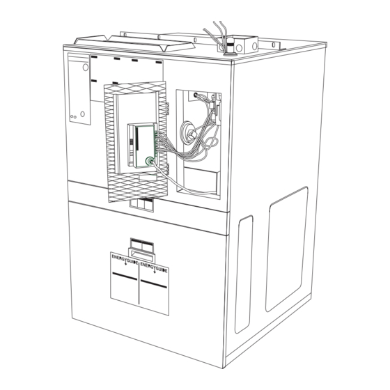
Page 51: Unit Tear Down
UNIT TEAR DOWN Magic-Pak: HW/HWC UNIT TEAR DOWN HWC units are comprised of two major sections. The heating section is located in the top half of the unit. It contains the heat exchanger and the majority of the components associated with the heating function: controls, burners, switches, etc.. - Page 52 Service Reference Manual UNIT TEAR DOWN PLATE MOUNTING SCREWS INDUCED DRAFT BLOWER/ COMBUSTION BLOWER HEAT EXCHANGER FRONT HEAT SECTION PANEL GAS VALVE HEATING SECTION VESTIBULE PANEL CONTROL SECTION BURNER TRAY COOLING SECTION BURNER ACCESS PANEL FILTER ACCESS DOOR Figure 3-1...
-
Page 53: Cooling Section Chassis Removal
UNIT TEAR DOWN Magic-Pak: HW/HWC Cooling Section Chassis Removal: The cooling chassis may be removed from behind the filter access door. Refer to the following directions and Figures 3-1 to 3-4. To remove the cooling chassis: 1. Disconnect all power to the unit. 2. - Page 54 Service Reference Manual UNIT TEAR DOWN EVAPORATOR BLOWER MOTOR Figure 3-3 EVAPORATOR COMPRESSOR EVAPORATOR DRAIN TUBE CONNECTION EVAPORATOR DRAIN PAN CHASSIS SHOWN PARTIALLY REMOVED LOW VOLTAGE MOLEX PLUG Figure 3-4 EVAPORATOR DRAIN PERMAGUM SEAL TUBE CONNECTION DRAIN HOSE (NOT PICTURED) ARMSTRONG P/N 03613A001 17"...
-
Page 55: Evaporator Blower Assembly Removal
UNIT TEAR DOWN Magic-Pak: HW/HWC Evaporator Blower Assembly Removal: The evaporator blower assembly is removable as one complete section. To remove the assembly, the chassis must be removed first (see page 3- 4). Refer to the following directions and Figure 3-5. To remove the evaporator blower assembly: 1. -
Page 56: Component Location Illustrations
Service Reference Manual COMPONENT LOCATION ILLUSTRATIONS Section 4 - Component Location Illustrations HW/HWC(3) Unit ......... 4-2 HW/HWC(2) Unit ......... 4-3 HW/HWC - Panels........ 4-4 HW/HWC - Exterior Louver/Grill Panel .. 4-5 HWC Chassis Assembly ......4-6 HWC Chassis Assembly - Top View ..4-7 HWC Chassis Assembly - Circulating Air Blower Partially Removed 4-8... - Page 57 COMPONENT LOCATION ILLUSTRATIONS Magic-Pak: HW/HWC HW/HWC123,183,243,303 IGNITION/BLOWER CONTROL BOARD (*24) UNITED TECHNOLOGIES 1097-83-400A/1097-400-I (DSI)* ARMSTRONG P/N 44990-001 MAIN LIMIT SWITCH (*52) ARMSTRONG P/N 40154B007 GAS VALVE HEATING SECTION HONEYWELL VR8105M8202 ARMSTRONG P/N 44987-001 CONTROL SECTION PRESSURE SWITCH (*57) COOLING SECTION BURNER TRAY * SEE COMPONENT SECTION FOR FURTHER DETAIL OF IGNITION/BLOWER CONTROL...
- Page 58 Service Reference Manual COMPONENT LOCATION ILLUSTRATIONS HW/HWC122, 182, 242, 302 FENWAL IGNITION CONTROL - 2 MODELS (*24) FENWAL TRITON 2461D 900-227 - ARMSTRONG P/N 43110-002 FENWAL 05-29 - ARMSTRONG P/N 39048B001 (SEE NOTE BELOW) MAIN LIMIT SWITCH (*52) INDUCED DRAFT BLOWER/ COMBUSTION BLOWER (*63) FLUE BOX ARMSTRONG P/N 41144-001...
- Page 59 COMPONENT LOCATION ILLUSTRATIONS Magic-Pak: HW/HWC HW/HWC - Panels TOP PANEL ASSEMBLY ARMSTRONG P/N 03455D007 HEAT EXCHANGER ACCESS PANEL ARMSTRONG P/N 38782D001 INSPECTION WINDOW SIDE PANEL ARMSTRONG P/N 38092A002 ARMSTRONG P/N 38769D001 UPPER LOUVER PANEL ARMSTRONG P/N 03545C000 LOWER GRILL PANEL ARMSTRONG P/N 03551D100 COOLING CONTROL...
- Page 60 Service Reference Manual COMPONENT LOCATION ILLUSTRATIONS HW/HWC Exterior Louver/Grill Panel SIDE VIEW CONDENSER AIR FLOW OUTLET EXTERIOR UPPER LOUVER PANEL ARMSTRONG P/N 03545C000 LOUVERS POINT UPWARD EXTERIOR LOWER GRILL PANEL AT 45° ANGLE ARMSTRONG P/N 03551D100 CONDENSER GRILL IS FLAT WITH AIR FLOW RECTANGULAR OPENINGS INLET...
- Page 61 COMPONENT LOCATION ILLUSTRATIONS Magic-Pak: HW/HWC HWC Chassis Assembly EVAPORATOR BLOWER MOTOR (*69) COMPRESSOR CONTACTOR (*278) ARMSTRONG P/N 03575C001 COMPRESSOR CAPACITOR (*271) CONDENSING FAN SHROUD CONDENSING FAN CONDENSER FAN (*267, 268) CAPACITOR (*271) CONDENSING COIL (*250) CAPILLARY TUBE BLOWER CONTROL BOARD (*5) METERING DEVICE (*256) ARMSTRONG P/N 39029B002 FILTER RETAINER...
- Page 62 Service Reference Manual COMPONENT LOCATION ILLUSTRATIONS HWC Chassis Assembly - Top View SEE FIGURE 4-7 FOR CIRCULATING AIR BLOWER COMPONENTS CONDENSER MOTOR (*267) (12-18) ARMSTRONG P/N 41282-001 (24-30) ARMSTRONG P/N 41254-001 CONDENSER FAN MOTOR BRACKET (*269) ARMSTRONG P/N 03982D004 FAN SHROUD FAN BLADE (*268) (12-18) ARMSTRONG P/N 39085B001 (3 BLADE/24°...
- Page 63 COMPONENT LOCATION ILLUSTRATIONS Magic-Pak: HW/HWC HWC Chassis Assembly - Circulating Air Blower Partially Removed BLOWER WHEEL (*73) ARMSTRONG P/N 34833B001 10.75" x 4" SEE FIGURE 4-6 FOR FAN CONDENSING PARTS CIRCULATING AIR BLOWER MOTOR (*69) (12) ARMSTRONG P/N 39045B001 BLOWER HOUSING (*74) (24-30) 39046B001 ARMSTRONG P/N 39010B001 MOTOR MOUNTING BRACKET (*71, 72)
- Page 64 Service Reference Manual UNIT COMPONENTS Section 5 - Unit Components Transformer ........5-3 Gas Valves ........... 5-4 White-Rodgers 25K49 ........ 5-4 Honeywell 8105 ......... 5-5 Blower Control Boards ......5-6 United Technologies Model 1010-611 ..5-6 Heatcraft Model IBC-H4C401 ..... 5-7 Ignition Controls ........
- Page 65 UNIT COMPONENTS Magic-Pak: HW/HWC HWC Capillary Tubes ......5-35 Capacitors ......... 5-39 Evaporator Blower Motor ....5-40 Condenser Fan Motor ......5-40 Capacitors-Run ........5-41 Fan Blades ......... 5-42 Exterior Grill Panels ......5-44...
-
Page 66: Unit Components
Service Reference Manual UNIT COMPONENTS Unit Components This section provides a brief description of the most important compo- nents within the Magic-Pak HW/HWC units. The information presented here is not intended to take the place of the instructions and printed literature packed with each component by the original manufacturer. -
Page 67: Gas Valves
UNIT COMPONENTS Magic-Pak: HW/HWC Gas Valves (*7) White-Rodgers 25K49-120 Gas Valve Specifications Manufacturer: White-Rodgers Model: 25K49-120 Armstrong P/N 43108-001 Dimensions: 1.97" W x 5.31" L Nominal Operating Currents: 25VAC/60Hz/.5A Regulator set at 3.50 +/– .02” W.C. at 55.6 cubic Ft./Hr of air at standard conditions (with valve in vertical position, inlet up). -
Page 68: Honeywell 8105
Service Reference Manual UNIT COMPONENTS Honeywell 8105 Series Gas Valve Specifications Manufacturer: Honeywell Model: VR8105M8202 Armstrong P/N 44987-001 Dimensions: 2.70" W x 4.75" L Nominal Operating Currents: 25VAC/60Hz/.5A Regulator Setting: 3.50 +/– .3" W.C. Pipe Size: .50" Inlet x .375" Outlet Valve Amp Draw: .5 A 1"... -
Page 69: Blower Control Boards
UNIT COMPONENTS Magic-Pak: HW/HWC Blower Control Boards (*5) A separate blower control board is used in the Magic-Pak HW/HWC models that do not use integrated ignition/blower control boards. Blower control boards from two different manufacturers are used in these HW and HWC units. -
Page 70: Heatcraft Model Ibc-H4C401
Service Reference Manual UNIT COMPONENTS Heatcraft Model IBC-H4C401 Blower Control Board Specifications Manufacturer: United Technologies Model: 1010-611 Armstrong P/N 39029B002 Operating Voltage: 18-30VAC 60 Hz 60 Hz Power Requirement: 4 VA max. Operating Temperature: – 40°F to +170°F Wiring Connections: All Male .250" x .032" Quick Connect Tabs Performance Specifications (all timings +/–... -
Page 71: Ignition Controls
UNIT COMPONENTS Magic-Pak: HW/HWC Ignition Controls (*24) Fenwal Triton 2461D Ignition Control Specifications Manufacturer: Fenwal Model: Triton 2461D Armstrong P/N 43110-002 Pre-purge: 30 seconds Ignition: 15 seconds Input: 24VAC, 50/60 Hz 300 mA Valve: 24VAC, 2.0 A max. Inducer: 120VAC, 3.0 A or 240VAC, 1.5 A, 1/4 HP Ambient: –... - Page 72 Service Reference Manual UNIT COMPONENTS Diagnostics (Fenwal Triton 2461D) 1. Diagnostic LED flash rate is 1/4 second “ON”, 1/4 second “OFF” followed by up to four seconds “OFF” before repeating the code. 2. Only one code is displayed at a time. 3.
-
Page 73: Fenwal 05-29 Dsi
UNIT COMPONENTS Magic-Pak: HW/HWC 5-10 Fenwal 05-29 DSI Ignition Control Specifications Manufacturer: Fenwal Model: 05-29 DSI Armstrong P/N 39048B001 Relative Humidity Rating: 5 to 90% RH at 95°F Flame Current: 3 mA min. Spark Gap: 1/8" Trial for Ignition: 6.8 seconds Pre-purge: 30 seconds Input: 24VAC from TS and P.SW to ground Gas Valve Contacts: 24VAC, 600 mA max. -
Page 74: Integrated Blower/Ignition Controls
Service Reference Manual UNIT COMPONENTS 5-11 Integrated Blower/Ignition Control (*24) United Technologies Model 1097-400-1 The integrated control combines the actions and purposes of the indi- vidual ignition and blower control boards found on other units. It automati- cally monitors and controls the operation of the gas burners, gas valve, induced draft blower and circulating blower. - Page 75 UNIT COMPONENTS Magic-Pak: HW/HWC 5-12 Diagnostics (United Technologies 1097-400-1) The following blower/ignition control board LED codes indicate normal or abnormal operations: TABLE 5-2 UTech Model 1097 Diagnostic Flash Code o i t f l l o i t f l l e l i o l l u l i...
- Page 76 Service Reference Manual UNIT COMPONENTS 5-13 United Technologies Model 1097-400-1 (cont.) Heat Mode Pre-purge 30 seconds Inter-purge 30 seconds Post-purge 5 seconds Trial Time 10 seconds # of Trials Board to reset from lockout after 60 minutes. Fan On Delay Cool 5 seconds (fixed) Heat...
-
Page 77: Induced Draft Blower
UNIT COMPONENTS Magic-Pak: HW/HWC 5-14 Induced Draft Blower (*63) The induced draft blower is also referred to as a “combustion” blower, since its purpose is to establish flow of combustion air through the heat exchanger. Mounted at the outlet of the secondary heat exchanger, the blower establishes a negative pressure within the heat exchanger and exhausts the flue products outside the structure. -
Page 78: Burners
Service Reference Manual UNIT COMPONENTS 5-15 Burners (*34) The Magic-Pak HW and HWC units covered in this manual use a burner design called the “inshot” type. No adjustment is provided for primary or secondary air. For best operation, keep the burners clean. Use the correct orifice size and adjust the manifold pressure for the fuel being used and the operating altitude. - Page 79 UNIT COMPONENTS Magic-Pak: HW/HWC 5-16 Flame Carryover Problems During ignition, the flame must travel uninterrupted from one burner to the rest of the burners. Causes: • Carryover “wing” on burner is plugged with insects or debris • Improper gap setting on wings •...
-
Page 80: Manifold Orifices
Service Reference Manual UNIT COMPONENTS 5-17 Manifold Orifices (*13) TABLE 5-3 Manifold Orifice Specifications Hole Diameter FIGURE 5-13 Manifold Orifice... -
Page 81: Contactor
UNIT COMPONENTS Magic-Pak: HW/HWC 5-18 Contactor (*278) Contactor Specifications Manufacturer: Honeywell Model: R8242A-1008 Armstrong P/N 7535C001 Single-phase, Single-pole, 25 F.L.A., 125 L.R.A Coil: 24VAC, 50/60 Hz Line Voltage: 240/277 Coil Resistance at 70°F: 8 - 10 ohms Low Voltage Coil Terminals Open Contact Closed Contact FIGURE 5-14 Honeywell Contactor Model R8242A-1008... -
Page 82: Main (High) Limit Switch
Service Reference Manual UNIT COMPONENTS 5-19 Main (High) Limit Switch (*52) A Normally Closed control that opens if abnormally high circulating air temperatures occur. It is an automatic reset control. Note: Several different main limit switches are used. Refer to the parts list for the correct limit switch. -
Page 83: Flame Rollout Switch
UNIT COMPONENTS Magic-Pak: HW/HWC 5-20 Flame Rollout Switch (*55) A Normally Closed switch that opens when abnormal temperatures occur in the burner area, caused by a restricted heat exchanger, causing main burner flame to “roll out” into the vestibule area. To reset the switch, push the button on top. -
Page 84: Pressure Switch
Service Reference Manual UNIT COMPONENTS 5-21 Pressure Switch (*57) These are Normally Open switches that react to a difference in pressure on an internal diaphragm. It will not allow ignition to start if the induced draft blower cannot produce sufficient negative pressure relative to atmospheric pressure or pressure in a sealed burner box. -
Page 85: Pressure Switch Problems
UNIT COMPONENTS Magic-Pak: HW/HWC 5-22 TABLE 5-4 Pressure Switches a t l i r t a t l i r t a t l i r t e t i a t l i r t – / a t l i r t –... - Page 86 Service Reference Manual UNIT COMPONENTS 5-23 The measured static pressure reading should be compared to the pres- sure switch specifications. If the measured static pressure meets or exceeds the specifications and switch contacts will not transfer, check the following items: •...
-
Page 87: Checking Pressure Switch Operation
UNIT COMPONENTS Magic-Pak: HW/HWC 5-24 Blocked Flue Blocked flue is any condition that blocks or restricts the flue (vent) pipe to a point where the pressure fall reaches the calibrated open setting of the pressure switch. Potential Causes: • Rodents •... - Page 88 Service Reference Manual UNIT COMPONENTS 5-25 What Is Needed for the Tests • A good general-purpose incline manometer with a range of 0 - 3" W.C. (Dwyer 1227 or equivalent). • Use the parts list to verify that the proper pressure switch is installed in the unit.
- Page 89 UNIT COMPONENTS Magic-Pak: HW/HWC 5-26 A Word About the “Switch Closed” Value Switch Closed is the pressure at which the contacts close as the induced draft blower comes up to speed. It is calculated by adding – 0.1" W.C. to the sum of the switch’s Open value and its upper tolerance.
- Page 90 Service Reference Manual UNIT COMPONENTS 5-27 Induced Draft Blower Pressure Switch 1/8" Tee -1" 1" 2" 3" = Tee installed for test purposes only Incline Manometer FIGURE 5-20 Incline Manometer Connection...
- Page 91 UNIT COMPONENTS Magic-Pak: HW/HWC 5-28 Compressors (*262) TABLE 5-5 Compressor Specifications (continued on next page) ) l l ) l l n i t ) l l l l o ) l l l l o ) l l n i t ) l l l l o ) l l...
- Page 92 Service Reference Manual UNIT COMPONENTS 5-29 y t i " ) " ) y t i " ) " ) y t i " ) " ) y t i " ) " ) y t i " ) " ) y t i "...
-
Page 93: Tecumseh
UNIT COMPONENTS Magic-Pak: HW/HWC 5-30 Manufacturer: Tecumseh TABLE 5-6 Tecumseh Rotary Compressor Specifications All measurements in inches unless otherwise specified. FIGURE 5-21 Tecumseh Rotary Compressor .75 Diameter Holes Top View .315 I.D.Copper Discharge Tube I.D. Copper Suction Tube .(43 - .50 Side View... - Page 94 Service Reference Manual UNIT COMPONENTS 5-31 Manufacturer: Tecumseh TABLE 5-7 Tecumseh Reciprocating Compressor Specifications 9.38 .753"/.756" I.D. Copper Suction Tube 12.647" 12.753” .378"/.381" I.D. Copper Discharge Tube 7.475" 7.525" (Between Centers of Holes) .750 /.760 Diameter (4 Holes) Side View FIGURE 5-22 Tecumseh Reciprocating Compressor...
-
Page 95: Copeland
UNIT COMPONENTS Magic-Pak: HW/HWC 5-32 Manufacturer: Copeland TABLE 5-8 Copeland Compressor Specifications All measurements in inches unless otherwise specified. 18 Ga. Thermal Protector Leads (12.13" Long) .500" I.D. Copper Discharge Tube .750" I.D. Copper-Plated Steel Suction Tube Side View 7.50 .765 Diameter (4 Holes) (Between Centers of Holes) FIGURE 5-23 Copeland Compressor... - Page 96 Service Reference Manual UNIT COMPONENTS 5-33 Manufacturer: Copeland TABLE 5-9 Copeland Compressor Specifications All measurements in inches unless otherwise specified. .750 Dia. 9.41 /9.62 (4 Holes) 7.50 (Typ.) 7.50 (Typ.) Top View .500" I.D. Copper Discharge Fitting Top View .750" I.D. Copper-Plated Steel Suction Fitting FIGURE 5-24 Copeland Compressor Side View...
-
Page 97: Drier-Filters
UNIT COMPONENTS Magic-Pak: HW/HWC 5-34 Drier-Filters (*301) TABLE 5-10 Drier-Filter Specifications Armstrong Part Number .108" 39059B001 .111" .114" 39059B002 .117" .108" 39059B003 .111" 4.38" +/– .13" A - I.D. .314" I.D. .317" B - # Holes 1.00 FIGURE 5-25 Drier-Filter... - Page 98 Service Reference Manual UNIT COMPONENTS 5-35 HWC Capillary Tubes (*256) TABLE 5-11 HWC Capillary Tube Specification Tables* " 4 " 6 " 5 " 4 " 6 " 4 " 9 " 2 " 6 " 4 " 6 " 4 "...
- Page 99 UNIT COMPONENTS Magic-Pak: HW/HWC 5-36 Notes: • All bends 90° unless otherwise noted. • Do not kink or flatten during forming. • Tape tubes together with masking tape. 14.00" 15.60" 11.89" Ref. 6.75" Ref. 7.25" Ref. 1.00 Rad. Typ. .75 Rad. Typ. 6.00"...
- Page 100 Service Reference Manual UNIT COMPONENTS 5-37 Notes: • All bends 90° unless otherwise noted. • Do not kink or flatten during forming. • Tape tubes together with masking tape. 1.25 10.70 14.74" Turns 13.13" Ref. 1.446 Diameter .75" Rad. Typ. 3.500"...
- Page 101 UNIT COMPONENTS Magic-Pak: HW/HWC 5-38 Notes: • All bends 90° unless otherwise noted. • Do not kink or flatten during forming. • Tape tubes together with masking tape. TABLE 5-12 39102B001 Specifications " 0 " 1 .75" 2.79" " 0 .25"...
- Page 102 Service Reference Manual UNIT COMPONENTS 5-39 Capacitors (*271) TABLE 5-13 Capacitor Ratings Rating Armstrong Volts Dual Single FIGURE 5-36 Capacitors...
-
Page 103: Evaporator Blower Motor
UNIT COMPONENTS Magic-Pak: HW/HWC 5-40 Evaporator Blower Motor - Indoor Blower (*69) TABLE 5-14 Evaporator Blower Motor Specifications Notes: • FLA and capacitor ratings may vary. Always check FLA and capacitor ratings on the motor data plate. • Motor diameter - 5.70", shaft size - .50", rotatin - CW lead end •... -
Page 104: Capacitors-Run
Service Reference Manual UNIT COMPONENTS 5-41 Capacitors-Run (*86) TABLE 5-16 Run Capacitor Ratings Rating Armstrong Volts... -
Page 105: Fan Blades
UNIT COMPONENTS Magic-Pak: HW/HWC 5-42 Fan Blades (*268) Notes: 1. 26° Pitch, 5 Blades 2. Material: 24 Ga. Galvalume 3. Set Screw: (2) 5/16"-24 x 5/8" long square head, cup point 3.79 +/ .09 18.00 +/ .06 .5002" Diameter Bore .5019"... - Page 106 Service Reference Manual UNIT COMPONENTS 5-43 Notes: 1. 24° Pitch, 3 Blades 2. Material: 24 Ga. Galvalume 3. Set Screw: (2) 5/16"-24 x 5/8" long square head, cup point 3.59 +/ .09 18.00 +/ .06 .5002" Diameter Bore .5019" Rotation AIR FLOW FIGURE 5-38 Fan Blades - HWC Models 242, 302 &...
-
Page 107: Exterior Grill Panels
UNIT COMPONENTS Magic-Pak: HW/HWC 5-44 Exterior Grill Panels (Not Listed in the Parts Lists) Upper Louver Panel Armstrong P/N 03545C000 Lower Grill Panel Armstrong P/N 03551D100 Refer to the Component Location Illustrations section beginning on page 4-1 for further detail of the exterior grill panels and other panels. FIGURE 5-39 Exterior Grill Panels... - Page 108 Service Reference Manual INSTALLATION Section 6 - Installation Location ..........6-3 Installing With Wall Sleeve....6-5 Installing Without Wall Sleeve ....6-6 Support..........6-6 Condensate Drain ......... 6-7 Venting ..........6-7 Removal of Unit from Common Venting System ........6-9 Gas Connections ........
- Page 109 INSTALLATION Magic-Pak: HW/HWC Installation and Operation in Extremely Cold Weather Areas ......6-15...
-
Page 110: Installation
Service Reference Manual INSTALLATION Installation Information in this section is provided for the convenience of the service technician, for the purpose of evaluating the installation during service and troubleshooting. It does not take the place of the complete Arm- strong Installation and Maintenance Instructions that are shipped with IMPORTANT: every Magic-Pak unit. - Page 111 INSTALLATION Magic-Pak: HW/HWC If three or more adjacent walls form an air shaft with Magic-Pak HW/HWC units facing each other in each wall, the separation between opposite walls should be increased by 20%. These “rule-of-thumb” dimensions are intended to minimize possibilities for recirculation of condenser air, or interaction between units.
- Page 112 Service Reference Manual INSTALLATION Installing With a Wall Sleeve CAUTION The sleeve is not intended as the sole support for the unit. Additional support must be provided near the return opening on the unit for adequate support. The use of vibration isolation material between the unit and the support is recommended.
-
Page 113: Support
INSTALLATION Magic-Pak: HW/HWC Installing Without a Wall Sleeve Refer to the following directions and Figure 6-1 on page 6-5 for guidance in installing the unit without a wall sleeve: 1. Measure the size of the unit and provide an opening in an outside wall that will accept the unit. -
Page 114: Condensate Drain
Service Reference Manual INSTALLATION Condensate Drain (HWC Models) Install the plastic drain tube (furnished) over the 5/8" O.D. fitting welded to the center of the condensate pan. Connect the other end of the drain tube to the open trap (see Figure 6-2). The plastic drain connection is provided so that it may be disconnected from the permanent drain tubing in the building in the event it becomes necessary to remove the cooling chassis assembly. - Page 115 INSTALLATION Magic-Pak: HW/HWC Special provisions must be made concerning the location of the vent termination with relation to building air inlets. A building air inlet is consid- ered to be any door, moveable window, gravity fresh air inlet or other opening where fresh outdoor air can be brought into the building.
-
Page 116: Removal Of Unit From Common Venting System
Service Reference Manual INSTALLATION Removal of Unit from Common Venting System When an existing furnace is removed from a common venting system serving other appliances, the venting system is likely to be too large to properly vent the remaining attached appliances. The following test should be conducted with each appliance while the other appliances connected to the common venting system are not in operation. - Page 117 INSTALLATION Magic-Pak: HW/HWC 6-10 Units for operation with propane must be converted with a kit supplied by the manufacturer and require for operation an inlet pressure of 11" W.C. minimum and 14" W.C. maximum. A regulator is also required on the propane tank.
-
Page 118: Electrical Connections
Service Reference Manual INSTALLATION 6-11 A manual shutoff valve must be located outside the unit. The use of a union located upstream of the controls is recommended, between the controls and the manual shutoff valve. This will facilitate removal of controls and manifold. -
Page 119: Thermostat
INSTALLATION Magic-Pak: HW/HWC 6-12 See Table 6-3 and the Specifications section beginning on page 1-1 for correct wire ampacity for the cooling chassis required, and size the wire accordingly. For HW (heating only units): When sizing wire, keep in mind that an air conditioning chassis may be added in the future. -
Page 120: Air Filter
Service Reference Manual INSTALLATION 6-13 inside the unit. Make sure that all sides of the duct are flanged over to permit removal of the cooling chassis if required. Use a flexible connec- tion to attach the remainder of the return duct. The return duct should be sealed to the unit casing and terminate outside the space containing the furnace. -
Page 121: Blower
INSTALLATION Magic-Pak: HW/HWC 6-14 To adjust the regulator, turn the adjusting screw on the regulator clock- wise to increase pressure and input or counterclockwise to decrease pressure and input. For natural gas installations, check the burner rate by observing the gas meter (making sure that all other gas appliances are turned off). - Page 122 Service Reference Manual INSTALLATION 6-15 Installation and Operation in Extremely Cold Weather Areas In areas where extremely cold (below – 20°F) outdoor temperatures can be expected, some additional installation and operating precautions should be taken. The following precautions are taken to prevent possible vent system ice blockage that could result in safety shutdown of the burners: 1.
- Page 123 Service Reference Manual A C C E S S O R I E S Section 7 - Accessories HW/HWC Accessory Kit Index ....7-2 CA-239 Wall Sleeve Kit ........7-3 A242-1 Wall Sleeve Adaptor Kit ...... 7-7 ALVR42 Architectural Louver Facade ..... 7-10 34961A001 Vibration Isolator ......
-
Page 124: Accessories
A C C E S S O R I E S Magic-Pak: HW/HWC Accessories There are a number of accessories available to increase the performance or versatility of the Armstrong Magic-Pak HW/HWC units. This section provides a general description of each. Note: Complete instructions are packaged with each kit or its components and accessories. -
Page 125: Ca-239 Wall Sleeve Kit
Service Reference Manual A C C E S S O R I E S CA-239 Wall Sleeve Kit The CA-239 wall sleeve kit is designed to facilitate the installation of Magic-Pak units by providing an accurate opening to properly accept a Magic-Pak unit. - Page 126 A C C E S S O R I E S Magic-Pak: HW/HWC TABLE 7-2 CA-239 Parts List Assembled Wall Sleeve Dimensions: 45" high x 29" wide x 12.5" deep Support Angle - 8 Holes Top Panel Front of Sleeve "...
-
Page 127: Wall Sleeve Installation
Service Reference Manual A C C E S S O R I E S Wall Sleeve Installation The wall sleeve can be installed from either the inside or the outside of the building. In any case, proper considerations must be made for final weather sealing of the wall sleeve and the Magic-Pak unit. - Page 128 A C C E S S O R I E S Magic-Pak: HW/HWC Magic-Pak Installation Before installing the Magic-Pak unit in the wall sleeve, it is important to consider the possibility of sound and vibration transmission through the wall. It is recommended that vibration isolation pads be installed evenly spaced across the outer edge of the bottom panel of the wall sleeve.
-
Page 129: A242-1 Wall Sleeve Adaptor Kit
Service Reference Manual A C C E S S O R I E S A242-1 Wall Sleeve Adaptor Kit The A242-1 wall sleeve adaptor kit is designed to allow for the installation of current 43" tall HW/HWC units into 48" tall wall sleeves (CA241 wall sleeve kits). - Page 130 A C C E S S O R I E S Magic-Pak: HW/HWC Attachment to HW/HWC After assembling the kit, it is ready to be attached to the top of the HW/ HWC unit. To attach the kit to the HW/HWC unit: 1.
- Page 131 Service Reference Manual A C C E S S O R I E S TABLE 7-3 A242-1 Parts List (2) #8 x ½" Screws in each rear corner Right Side Rear " 2 " 4 " 4 (2) #8 x ½" Screws "...
- Page 132 A C C E S S O R I E S Magic-Pak: HW/HWC 7-10 ALVR42 Architectural Aluminum Louver Facade In many applications, architects and installers will choose to use facades over the front of Magic-Pak units. Often this is done to improve the appearance of a building.
- Page 133 Service Reference Manual A C C E S S O R I E S 7-11 The louver will fit directly against the front of the unit. However, the lower lip of the unit will protrude into the louver. The louver must be positioned to accommodate the protruding lower lip.
- Page 134 A C C E S S O R I E S Magic-Pak: HW/HWC 7-12 34961A001 Compressor Vibration Isolator The 34961A001 spring/grommet kit is designed to isolate vibrations common to most compressors away from the base of Magic-Pak units and building walls. Some types of wall construction will be especially susceptible to vibration transmissions.
- Page 135 Service Reference Manual A C C E S S O R I E S 7-13 Use of spray lubricant or liquid soap will aid in the installation of rubber parts. Compressor belly is rounded and can be “rocked” on the belly support. It is easiest to install one spring grommet at a time.
-
Page 136: Alpkt389-2 L.p. Gas Conversion Kit
A C C E S S O R I E S Magic-Pak: HW/HWC 7-14 ALPKT389-2 L.P. Gas Conversion Kit The ALPKT389-2 kit contains the following parts to convert the 26, 38, 51 and 64HW/HWC series gas furnace from natural gas to propane gas. For altitudes from 2000 - 4500 feet, a high altitude kit as supplied by the manufacturer must be used (see page 7-15). -
Page 137: Ahalt390-1 High Altitude Kit
Service Reference Manual A C C E S S O R I E S 7-15 AHALT390-1 High Altitude Kit The AHALT390-1 kit contains the following parts to convert the 26, 38, 51 and 64HW/HWC series units to high altitude for natural or propane gas. If the field conversion is for high altitude propane gas, be sure to install the appropriate gas valve conversion kit (see page 7-14). - Page 138 A C C E S S O R I E S Magic-Pak: HW/HWC 7-16 BTU/HR = Cubic Feet Per Revolution Heating x 3600 x INPUT # Seconds Per Revolution Value The heating value of your gas can be obtained from your local utility. With proper manifold pressure achieved, cycle main burners on and off.
-
Page 139: Time Delay Relay
Service Reference Manual A C C E S S O R I E S 7-17 ATIMR466-1 Short Cycle Protector Kit The ATIMR466-1 Short Cycle Protector Kit helps guard against compres- sor failure due to repeated, short interval on/off cycles. It is also referred to as the Nuisance Blower Operation Repair Kit. -
Page 140: Adapt420-2 Chassis Conversion Kit
A C C E S S O R I E S Magic-Pak: HW/HWC 7-18 ADAPT420-2 Chassis Conversion Kit The ADAPT420-2 kit was designed to retrofit an HWC122, 182, 242 or 302 chassis onto a cabinet originally equipped with an HWC12, 18, 24 or 30 chassis. -
Page 141: Fenwal Triton Ignition Control Kit
Service Reference Manual A C C E S S O R I E S 7-19 Fenwal Triton Ignition Control Kit This kit enables the Fenwal “Triton” local sense, one-hour retry, direct spark ignition (DSI) control to be used as a service parts replacement for earlier versions of Fenwal DSI controls used on HW/HWC models. -
Page 142: Tl109 Burner Tray Kits
A C C E S S O R I E S Magic-Pak: HW/HWC 7-20 TL109 Burner Tray Kit The TL109 Burner Tray Kit is designed for use in HW/HWC’s that were originally equipped with single port inshot burners. Four kits are available, one for each natural gas heating input rating as follows: •... - Page 143 Service Reference Manual A C C E S S O R I E S 7-21 AMUFFKT494-1 Discharge Muffler Kit In the event that during operation an unacceptable noise occurs, a muffler kit (AMUFFKT494-1) may be installed in the discharge line*. The cham- ber of the muffler acts as a sound-absorbing chamber reducing compres- sor pulsation noises.
-
Page 144: Parts Lists
Service Reference Manual PARTS LISTS Section 8 - Parts Lists HWC123, 183, 243, 303-1 ....8-2 HWC182, 242-11 ........ 8-5 HWC122, 242-10 ........ 8-7 HWC182-9 ........8-10 HWC242, 302-9 ........ 8-12 HWC122, 182, 242, 302-8 ....8-14 HWC182-6/7 ........8-17 HWC122, 282, 242, 302-5 .... - Page 145 PARTS LISTS MAGIC-PAK: HW/HWC HWC3-A-1 REVISED 4-26-99 TO SELECT PART # Last letter of the Model # is the Service Level. 64HWC303A-1A First find Model #. ------------------------------------------------ > 64HWC303A-1(*) Then match Service Level for desired part. ---------------- > PART DESCRIPTION REF PART #...
- Page 146 Service Reference Manual PARTS LISTS HWC3-A-1 REVISED (cont.) 4-26-99 TO SELECT PART # Last letter of the Model # is the Service Level. 64HWC303A-1A First find Model #. ------------------------------------------------ > 64HWC303A-1(*) Then match Service Level for desired part. ---------------- > REF PART # PART DESCRIPTION "...
- Page 147 PARTS LISTS MAGIC-PAK: HW/HWC HWC3-A-1 REVISED (cont.) 4-26-99 TO SELECT PART # Last letter of the Model # is the Service Level. 64HWC303A-1A First find Model #. ------------------------------------------------ > 64HWC303A-1(*) Then match Service Level for desired part. ---------------- > REF PART # PART DESCRIPTION...
- Page 148 Service Reference Manual PARTS LISTS HWC182-242A-11 REVISED 1-20-98 TO SELECT PART # Last letter of the Model # is the Service Level. 38HWC242A-11A First find Model #. -------------------------------------------------------------- > 38HWC242A-11(*) Then match Service Level for desired part. ------------------------------ > REF PART # PART DESCRIPTION...
- Page 149 PARTS LISTS MAGIC-PAK: HW/HWC REVISED HWC182-242A-11 (cont.) 1-20-98 TO SELECT PART # Last letter of the Model # is the Service Level. 38HWC242A-11A First find Model #. -------------------------------------------------------------- > 38HWC242A-11(*) Then match Service Level for desired part. ------------------------------ > REF PART # PART DESCRIPTION "...
- Page 150 Service Reference Manual PARTS LISTS HWC122-242A-10 REVISED 4-26-99 TO SELECT PART # Last letter of the Model # is the Service Level. 38HWC242A-10A First find Model #. -------------------------------------------------------------- > 38HWC242A-10(*) Then match Service Level for desired part. ------------------------------ > PART # PART DESCRIPTION...
- Page 151 PARTS LISTS MAGIC-PAK: HW/HWC HWC122-242A-10 REVISED (cont.) 4-26-99 TO SELECT PART # Last letter of the Model # is the Service Level. 38HWC242A-10A First find Model #. -------------------------------------------------------------- > 38HWC242A-10(*) Then match Service Level for desired part. ------------------------------ > PART # PART DESCRIPTION "...
- Page 152 Service Reference Manual PARTS LISTS HWC122-242A-10 REVISED (cont.) 4-26-99 TO SELECT PART # Last letter of the Model # is the Service Level. 38HWC242A-10A First find Model #. -------------------------------------------------------------- > 38HWC242A-10(*) Then match Service Level for desired part. ------------------------------ > PART # PART DESCRIPTION...
- Page 153 PARTS LISTS MAGIC-PAK: HW/HWC 8-10 HWC182-9 REVISED 1-20-98 TO SELECT PART # Last letter of the Model # is the Service Level. 64HWC182A-9A First find Model #. -------------------------------------------------------------- > 64HWC182A-9(*) Then match Service Level for desired part. ------------------------------ > REF PART # PART DESCRIPTION...
-
Page 154: Part Description
Service Reference Manual PARTS LISTS 8-11 REVISED HWC182-9 (cont.) 1-20-98 TO SELECT PART # Last letter of the Model # is the Service Level. 64HWC182A-9A First find Model #. -------------------------------------------------------------- > 64HWC182A-9(*) Then match Service Level for desired part. ------------------------------ > REF PART # PART DESCRIPTION "... - Page 155 PARTS LISTS MAGIC-PAK: HW/HWC 8-12 HWC242-302-9 REVISED 1-20-98 TO SELECT PART # Last letter of the Model # is the Service Level. 64HWC302A-9A First find Model #. -------------------------------------------------------------- > 64HWC302A-9(*) Then match Service Level for desired part. ------------------------------ > REF PART # PART DESCRIPTION...
- Page 156 Service Reference Manual PARTS LISTS 8-13 REVISED HWC242-302-9 (cont.) 1-20-98 TO SELECT PART # Last letter of the Model # is the Service Level. 64HWC302A-9A First find Model #. -------------------------------------------------------------- > 64HWC302A-9(*) Then match Service Level for desired part. ------------------------------ > REF PART # PART DESCRIPTION "...
- Page 157 PARTS LISTS MAGIC-PAK: HW/HWC 8-14 HWC-8 REVISED 1-20-98 TO SELECT PART # Last letter of the Model # is the Service Level. 64HWC302-8A First find Model #. ------------------------------------------------ > 64HWC302-8(*) Then match Service Level for desired part. ---------------- > REF PART # PART DESCRIPTION...
- Page 158 Service Reference Manual PARTS LISTS 8-15 HWC-8 REVISED (cont.) 1-20-98 TO SELECT PART # Last letter of the Model # is the Service Level. 64HWC302-8A First find Model #. ------------------------------------------------ > 64HWC302-8(*) Then match Service Level for desired part. ---------------- > REF PART # PART DESCRIPTION "...
- Page 159 PARTS LISTS MAGIC-PAK: HW/HWC 8-16 REVISED HWC-8 (cont.) 1-20-98 TO SELECT PART # Last letter of the Model # is the Service Level. 64HWC302-8A First find Model #. ------------------------------------------------ > 64HWC302-8(*) Then match Service Level for desired part. ---------------- > REF PART # PART DESCRIPTION...
- Page 160 Service Reference Manual PARTS LISTS 8-17 HWC-6/7 REVISED 1-20-98 TO SELECT PART # Last letter of the Model # is the Service Level. 64HWC182-6A First find Model #. -------------------------------------------------------------- > 64HWC182-6(*) Then match Service Level for desired part. ------------------------------ > REF PART # PART DESCRIPTION...
- Page 161 PARTS LISTS MAGIC-PAK: HW/HWC 8-18 REVISED HWC-6/7 (cont.) 1-20-98 TO SELECT PART # Last letter of the Model # is the Service Level. 64HWC182-6A First find Model #. -------------------------------------------------------------- > 64HWC182-6(*) Then match Service Level for desired part. ------------------------------ > REF PART # PART DESCRIPTION "...
- Page 162 Service Reference Manual PARTS LISTS 8-19 HWC-5 REVISED 1-20-98 TO SELECT PART # Last letter of the Model # is the Service Level. 64HWC302-5A First find Model #. ------------------------------------------------ > 64HWC302-5(*) Then match Service Level for desired part. ---------------- > REF PART # PART DESCRIPTION...
- Page 163 PARTS LISTS MAGIC-PAK: HW/HWC 8-20 HWC-5 REVISED (cont.) 1-20-98 TO SELECT PART # Last letter of the Model # is the Service Level. 64HWC302-5A First find Model #. ------------------------------------------------ > 64HWC302-5(*) Then match Service Level for desired part. ---------------- > REF PART # PART DESCRIPTION "...
- Page 164 Service Reference Manual PARTS LISTS 8-21 HWC-5 REVISED (cont.) 1-20-98 TO SELECT PART # Last letter of the Model # is the Service Level. 64HWC302-5A First find Model #. ------------------------------------------------ > 64HWC302-5(*) Then match Service Level for desired part. ---------------- > REF PART # PART DESCRIPTION...
- Page 165 PARTS LISTS MAGIC-PAK: HW/HWC 8-22 HWC-4 REVISED 1-20-98 TO SELECT PART # Last letter of the Model # is the Service Level. 38HWC182-4A First find Model #. -------------------------------------------------------------- > 38HWC182-4(*) Then match Service Level for desired part. ------------------------------ > REF PART # PART DESCRIPTION...
- Page 166 Service Reference Manual PARTS LISTS 8-23 REVISED HWC-4 (cont.) 1-20-98 TO SELECT PART # Last letter of the Model # is the Service Level. 38HWC182-4A First find Model #. -------------------------------------------------------------- > 38HWC182-4(*) Then match Service Level for desired part. ------------------------------ > REF PART # PART DESCRIPTION "...
- Page 167 PARTS LISTS MAGIC-PAK: HW/HWC 8-24 REVISED HWC-4 (cont.) 1-20-98 TO SELECT PART # Last letter of the Model # is the Service Level. 38HWC182-4A First find Model #. -------------------------------------------------------------- > 38HWC182-4(*) Then match Service Level for desired part. ------------------------------ > REF PART # PART DESCRIPTION...
- Page 168 Service Reference Manual PARTS LISTS 8-25 HWC-3 REVISED 1-20-98 TO SELECT PART # Last letter of the Model # is the Service Level. 64HWC302-3A First find Model #. ------------------------------------------------ > 64HWC302-3(*) Then match Service Level for desired part. ---------------- > REF PART # PART DESCRIPTION .
- Page 169 PARTS LISTS MAGIC-PAK: HW/HWC 8-26 HWC-3 REVISED (cont.) 1-20-98 TO SELECT PART # Last letter of the Model # is the Service Level. 64HWC302-3A First find Model #. ------------------------------------------------ > 64HWC302-3(*) Then match Service Level for desired part. ---------------- > REF PART # PART DESCRIPTION...
- Page 170 Service Reference Manual PARTS LISTS 8-27 HWC-3 REVISED (cont.) 1-20-98 TO SELECT PART # Last letter of the Model # is the Service Level. 64HWC302-3A First find Model #. ------------------------------------------------ > 64HWC302-3(*) Then match Service Level for desired part. ---------------- > REF PART # PART DESCRIPTION...
- Page 171 PARTS LISTS MAGIC-PAK: HW/HWC 8-28 HWC-2 REVISED 1-20-98 TO SELECT PART # Last letter of the Model # is the Service Level. 64HWC182-2A First find Model #. -------------------------------------------------------------- > 64HWC182-2(*) Then match Service Level for desired part. ------------------------------ > REF PART # PART DESCRIPTION .
- Page 172 Service Reference Manual PARTS LISTS 8-29 REVISED HWC-2 (cont.) 1-20-98 TO SELECT PART # Last letter of the Model # is the Service Level. 64HWC182-2A First find Model #. -------------------------------------------------------------- > 64HWC182-2(*) Then match Service Level for desired part. ------------------------------ > REF PART # PART DESCRIPTION...
- Page 173 PARTS LISTS MAGIC-PAK: HW/HWC 8-30 HWC-1 REVISED 1-20-98 TO SELECT PART # Last letter of the Model # is the Service Level. 64HWC302-1A First find Model #. ------------------------------------------------ > 64HWC302-1(*) Then match Service Level for desired part. ---------------- > PART DESCRIPTION REF PART # .
- Page 174 Service Reference Manual PARTS LISTS 8-31 HWC-1 REVISED (cont.) 1-20-98 TO SELECT PART # Last letter of the Model # is the Service Level. 64HWC302-1A First find Model #. ------------------------------------------------ > 64HWC302-1(*) Then match Service Level for desired part. ---------------- > REF PART # PART DESCRIPTION...
- Page 175 PARTS LISTS MAGIC-PAK: HW/HWC 8-32 REVISED HWC-1 (cont.) 1-20-98 TO SELECT PART # Last letter of the Model # is the Service Level. 64HWC302-1A First find Model #. ------------------------------------------------ > 64HWC302-1(*) Then match Service Level for desired part. ---------------- > REF PART # PART DESCRIPTION...
- Page 176 Service Reference Manual PARTS LISTS 8-33 HW-1 REVISED 1-20-98 TO SELECT PART # Last letter of the Model # is the Service Level. 64HW-1A First find Model #. -------------------------------------------------------------- > 64HW-1(*) Then match Service Level for desired part. ------------------------------ > REF PART # PART DESCRIPTION .
- Page 177 PARTS LISTS MAGIC-PAK: HW/HWC 8-34 HW-1 REVISED (cont.) 1-20-98 TO SELECT PART # Last letter of the Model # is the Service Level. 64HW-1A First find Model #. -------------------------------------------------------------- > 64HW-1(*) Then match Service Level for desired part. ------------------------------ > REF PART # PART DESCRIPTION...
- Page 178 Service Reference Manual PARTS LISTS 8-35 HWA-9 REVISED 4-26-99 TO SELECT PART # Last letter of the Model # is the Service Level. 64HWA-9A First find Model #. -------------------------------------------------------------- > 64HWA-9(*) Then match Service Level for desired part. ------------------------------ > PART # PART DESCRIPTION...
- Page 179 PARTS LISTS MAGIC-PAK: HW/HWC 8-36 HWA-9 REVISED (cont.) 4-26-99 TO SELECT PART # Last letter of the Model # is the Service Level. 64HWA-9A First find Model #. -------------------------------------------------------------- > 64HWA-9(*) Then match Service Level for desired part. ------------------------------ > PART # PART DESCRIPTION "...
- Page 180 Service Reference Manual PARTS LISTS 8-37 HWC3-S-1 REVISED 4-26-99 TO SELECT PART # Last letter of the Model # is the Service Level. 64HWC303SA-1A First find Model #. ------------------------------------------------ > 64HWC303SA-1(*) Then match Service Level for desired part. ---------------- > REF PART # PART DESCRIPTION...
- Page 181 PARTS LISTS MAGIC-PAK: HW/HWC 8-38 HWC3-S-1 REVISED (cont.) 4-26-99 TO SELECT PART # Last letter of the Model # is the Service Level. 64HWC303SA-1A First find Model #. ------------------------------------------------ > 64HWC303SA-1(*) Then match Service Level for desired part. ---------------- > REF PART # PART DESCRIPTION "...
- Page 182 Service Reference Manual PARTS LISTS 8-39 HWC3-S-1 REVISED (cont.) 4-26-99 TO SELECT PART # Last letter of the Model # is the Service Level. 64HWC303SA-1A First find Model #. ------------------------------------------------ > 64HWC303SA-1(*) Then match Service Level for desired part. ---------------- > REF PART # PART DESCRIPTION...
- Page 183 PARTS LISTS MAGIC-PAK: HW/HWC 8-40 HWC3-H-1 REVISED 4-26-99 TO SELECT PART # Last letter of the Model # is the Service Level. 64HWC303HA-1A First find Model #. ------------------------------------------------ > 64HWC303HA-1(*) Then match Service Level for desired part. ---------------- > REF PART # PART DESCRIPTION...
- Page 184 Service Reference Manual PARTS LISTS 8-41 HWC3-H-1 REVISED (cont.) 4-26-99 TO SELECT PART # Last letter of the Model # is the Service Level. 64HWC303HA-1A First find Model #. ------------------------------------------------ > 64HWC303HA-1(*) Then match Service Level for desired part. ---------------- > REF PART # PART DESCRIPTION "...
- Page 185 PARTS LISTS MAGIC-PAK: HW/HWC 8-42 HWC3-H-1 REVISED (cont.) 4-26-99 TO SELECT PART # Last letter of the Model # is the Service Level. 64HWC303HA-1A First find Model #. ------------------------------------------------ > 64HWC303HA-1(*) Then match Service Level for desired part. ---------------- > REF PART # PART DESCRIPTION...
-
Page 186: Troubleshooting/Performance/Charge Weights
Service Reference Manual TROUBLESHOOTING Section 9 - Troubleshooting/ Performance/ Charge Weights Troubleshooting ........9-2 Compressor Checkout ........ 9-2 Capacitor Checkout ........9-6 Performance ........9-9 Performance Tests (Installed) ...... 9-9 Performance Tests (Bench Tested) ..... 9-11 Charge Weights ......... 9-11... -
Page 187: Troubleshooting
TROUBLESHOOTING Magic-Pak: HW/HWC Troubleshooting Compressor Checkout The objective of this section is to help in diagnosing compressor prob- lems. It presents a series of tests that should be conducting before a determination on the condition of the compressor is made. This section has been organized so that the simplest checks are done first, followed by the more detailed tests (if necessary). - Page 188 Service Reference Manual TROUBLESHOOTING 2. Set an ohm meter to the lowest possible setting. On a note pad, write the following: “C to ground”, “S to ground” and “R to ground.” 3. Using the ohm meter, check for continuity between C terminal on the fusite plug and the case of the compressor (a spot may have to be cleaned on the compressor to get a good reading.) Record what was observed on the note pad next to the heading “C to ground”.
- Page 189 TROUBLESHOOTING Magic-Pak: HW/HWC When the resistance of “C to S” is added to the resistance of “C to R”, the combination is the total resistance of the entire motor windings circuit. 2. Compare the total to the reading taken between “S to R.” If the windings are in good condition, the sum of “C to S”...
- Page 190 Service Reference Manual TROUBLESHOOTING overload protector has opened. Before the compressor can be con- demned as having a burned out start or run winding, it must be deter- mined that the overload switch is in fact closed. It may take several hours for the compressor to cool down enough to guarantee that the switch has closed.
-
Page 191: Capacitor Checkout
TROUBLESHOOTING Magic-Pak: HW/HWC Capacitor Checkout Before starting the checkout of the capacitor, it is important to understand what a capacitor is, how it works and what its function is in relation to a motor. A capacitor is a storage device similar to a battery, only unlike a battery a capacitor wants to give up its energy all at once. - Page 192 Service Reference Manual TROUBLESHOOTING The following information is found on a capacitor: the MFD (microfarad rating) and the working voltage. Compare this to the rating plate on the motor or the information provided with the unit. The following are some of the problems that could be caused by a defective or incorrect capacitor: •...
- Page 193 TROUBLESHOOTING Magic-Pak: HW/HWC Ammeter (10 Loops) Fuse Nominal Capacitor Voltmeter Voltage To Be Tested Source FIGURE 9-1 Determining Capacitance (MFD) Rating with a Test Cord Before starting the test, take a reading of the line voltage at the outlet that will be used.
-
Page 194: Performance
Service Reference Manual TROUBLESHOOTING Performance Performance Checkout HW/HWC chassis come with a pre-charged chassis assembly. The chassis assembly is designed in a way that the unit may be run indepen- dently of the HWC unit. When the chassis is run on a floor or bench, the performance measurements will be affected due to the change in static pressures, recirculated air, excessive temperatures and equal ambient temperatures from indoor to outdoor. -
Page 195: Performance Tests (Bench Tested)
TROUBLESHOOTING Magic-Pak: HW/HWC 9-10 Performance Tests (Chassis Installed in Unit) - cont. TABLE 9-3 HWC242 Performance Test (Chassis Installed) Outdoor Air Temperature Entering Outdoor Coil 85° 95° 105° 115° Total Enter. Suction Suction Liquid Suction Suction Liquid Suction Suction Liquid Suction Suction Liquid... - Page 196 Service Reference Manual TROUBLESHOOTING 9-11 Performance Tests (Chassis Bench Tested) TABLE 9-5 70 - 80° Ambient Temperature Chassis Bench Test ° 5 ° 3 ° 0 ° 8 ° 3 ° 5 ° 3 ° 7 ° 0 ° 4 °...
Need help?
Do you have a question about the HWC PREMIER 122 and is the answer not in the manual?
Questions and answers