Table of Contents
Advertisement
Quick Links
Download this manual
See also:
User Manual
Advertisement
Table of Contents

Related Manuals for Alcatel OMNISTACK 6300-24


Summary of Contents for Alcatel OMNISTACK 6300-24
-
Page 1: Getting Started Guide
Part No. 060190-10, Rev. A December 2003 OmniStack 6300-24 ® Getting Started Guide... - Page 2 An Alcatel service agreement brings your company the assurance of 7x24 no-excuses technical support. You’ll also receive regular software updates to maintain and maximize your Alcatel product’s features and functionality and on-site hardware replacement through our global network of highly qualified service delivery partners. Additionally, with 24-hour-a-day access to Alcatel’s Service and Support web page, you’ll be able to view and update any case (open or closed) that you have reported to Alcatel’s technical support, open a new case or access helpful release notes, technical...
- Page 3 Warning This equipment has been tested and found to comply with the limits for Class B digital device pursuant to Part 15 of the FCC Rules. These limits are designed to provide reasonable protection against harmful interference when the equipment is operated in a commercial environment.
- Page 5 Compliances and Safety Warnings FCC - Class B This equipment has been tested and found to comply with the limits for a Class B digital device, pursuant to Part 15 of the FCC Rules. These limits are designed to provide reasonable protection against harmful interference in a residential installation.
- Page 6 • Immunity to conducted disturbances, Induced by radio-frequency fields: EN 61000-4-6:1996 (0.15 - 80 MHz with 1 kHz AM 80% Modulation: 3 V/m) • Power frequency magnetic field immunity test according to EN 61000-4-8:1993 (1 A/m at frequency 50 Hz) •...
-
Page 7: Safety Compliance
Safety Compliance Warning: Fiber Optic Port Safety When using a fiber optic port, never look at the transmit laser while it is powered on. Also, never look directly at the fiber TX port and fiber cable CLASS I LASER DEVICE ends when they are powered on. - Page 8 Wichtige Sicherheitshinweise (Germany) Bitte lesen Sie diese Hinweise sorgfältig durch. Heben Sie diese Anleitung für den späteren Gebrauch auf. Vor jedem Reinigen ist das Gerät vom Stromnetz zu trennen. Verwenden Sie keine Flüssigoder Aerosolreiniger. Am besten eignet sich ein angefeuchtetes Tuch zur Reinigung.
-
Page 9: Warnings And Cautionary Messages
Warnings and Cautionary Messages Warning: This product does not contain any servicable user parts. Warning: When connecting this device to a power outlet, connect the field ground lead on the tri-pole power plug to a valid earth ground line to prevent electrical hazards. -
Page 10: Related Publications
Purpose This guide details the hardware features of the OmniStack 6300 switch, including Its physical and performance-related characteristics, and how to install the switch. Related Publications The following publication gives specific information on how to operate and use the management functions of the switch: The OmniStack 6300 User Guide Also, as part of the switch’s firmware, there is an online web-based help that describes all management related features. -
Page 11: Table Of Contents
Contents Chapter 1: Introduction Overview Switch Architecture Network Management Options Description of Hardware 10/100/1000BASE-T Ports SFP Slots Status LEDs Optional Backup Power Supply Power Supply Receptacles Features and Benefits Connectivity Expandability Performance Management Chapter 2: Network Planning Introduction to Switching Application Examples Collapsed Backbone Network Aggregation Plan... - Page 12 Contents Twisted-Pair Devices Cabling Guidelines Connecting to PCs, Servers, Hubs and Switches Network Wiring Connections Fiber Optic SFP Devices Connectivity Rules 1000BASE-T Cable Requirements 1000 Mbps Gigabit Ethernet Collision Domain 100 Mbps Fast Ethernet Collision Domain 10 Mbps Ethernet Collision Domain Cable Labeling and Connection Records Appendix A: Troubleshooting Diagnosing Switch Indicators...
- Page 13 Tables Table 1-1. Port Status LEDs Table 1-2. System Status LEDs Table 3-1. Serial Cable Wiring Table 4-1. Maximum 1000BASE-T Gigabit Ethernet Cable Length Table 4-2. Maximum 1000BASE-SX Gigabit Ethernet Cable Lengths Table 4-3. Maximum 1000BASE-LX Gigabit Ethernet Cable Length Table 4-4.
- Page 14 Tables...
- Page 15 Figures Figure 1-1. Front and Rear Panels Figure 1-2. Port LEDs Figure 1-3. System LEDs Figure 1-4. Power Supply Receptacle Figure 2-1. Collapsed Backbone Figure 2-2. Network Aggregation Plan Figure 2-3. Remote Connection with Fiber Cable Figure 2-4. Making VLAN Connections Figure 3-1.
- Page 16 Figures...
-
Page 17: Chapter 1: Introduction
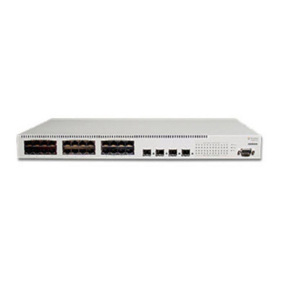
Chapter 1: Introduction Overview The Gigabit Ethernet Switch is an intelligent multilayer switch (Layer 2 and 4) with 24 10/100/1000BASE-T ports, four of which are combination ports that are shared with four SFP transceiver slots. There is also an SNMP-based management agent embedded on the main board. -
Page 18: Description Of Hardware
Introduction connection (in-band) using Telnet, the on-board Web agent, or Windows-based network management software. For a detailed description of the switch’s advanced features, refer to the User Guide. Description of Hardware 10/100/1000BASE-T Ports These ports are RJ-45 ports that operate at 10 Mbps or 100 Mbps, half or full duplex, or at 1000 Mbps, full duplex. -
Page 19: Status Leds
Description of Hardware Status LEDs The LEDs, which are located on the front panel for easy viewing, are shown below and described in the following table. Link/Act SFP LEDs Figure 1-2. Port LEDs Table 1-1. Port Status LEDs Port Status LEDs Condition Status RJ-45 Ports... -
Page 20: Table 1-2. System Status Leds
Introduction Power Indicator Diagnostic Indicator Redundant Power Indicator Figure 1-3. System LEDs Table 1-2. System Status LEDs System Status LEDs Condition Status Power On Green Switch is receiving power. Power off or failure. Diag Flashing Green System self-diagnostic test in progress. On Green System self-diagnostic test successfully completed. -
Page 21: Optional Backup Power Supply
Features and Benefits Optional Backup Power Supply The switch supports an optional Backup Power Supply (BPS), that can supply power to the switch in the event of failure of the internal power supply. Power Supply Receptacles There are two power receptacles on the rear panel of the switch. The standard power receptacle is for the AC power cord. -
Page 22: Management
Introduction Management • “At-a-glance” LEDs for easy troubleshooting • Network management agent: • Manages switch in-band or out-of-band • Supports Telnet, SNMP/RMON and Web-based interface... -
Page 23: Chapter 2: Network Planning
Chapter 2: Network Planning Introduction to Switching A network switch allows simultaneous transmission of multiple packets via non-crossbar switching. This means that it can partition a network more efficiently than bridges or routers. The switch has, therefore, been recognized as one of the most important building blocks for today’s networking technology. -
Page 24: Application Examples
Network Planning Application Examples This Gigabit Ethernet Switch is not only designed to segment your network, but also to provide a wide range of options in setting up network connections and linking VLANs. Some typical applications are described below. Collapsed Backbone The Gigabit Ethernet Switch is an excellent choice for mixed Ethernet, Fast Ethernet, and Gigabit Ethernet installations where significant growth is expected in the near future. -
Page 25: Network Aggregation Plan
Application Examples Network Aggregation Plan With 24 parallel bridging ports (i.e., 24 distinct collision domains), the Gigabit Ethernet Switch can collapse a complex network down into a single efficient bridged node, increasing overall bandwidth and throughput. In the figure below, the 10/100/1000BASE-T ports on the Gigabit Ethernet Switch are providing 1000 Mbps connectivity for up to 24 segments through stackable switches. -
Page 26: Remote Connection With Fiber Cable
Network Planning Remote Connection with Fiber Cable Fiber optic technology allows for longer cabling than any other media type. A 1000BASE-SX (MMF) link can connect to a site up to 550 meters away, and a 1000BASE-LX (SMF) link can run up to 5 km. This allows the Gigabit Ethernet Switch to serve as a collapsed backbone, providing direct connectivity for a widespread LAN. -
Page 27: Making Vlan Connections
Application Examples Making VLAN Connections VLANs can be based on port groups, or each data frame can be explicitly tagged to identify the VLAN group to which it belongs. When using port-based VLANs, ports can either be assigned to one specific group or to all groups. Port-based VLANs are suitable for small networks. -
Page 28: Application Notes
Network Planning Application Notes Full-duplex operation only applies to point-to-point access (such as when a switch is attached to a workstation, server or another switch). When the switch is connected to a hub, both devices must operate in half-duplex mode. Avoid using flow control on a port connected to a hub unless it is actually required to solve a problem. -
Page 29: Chapter 3: Installing The Switch
Chapter 3: Installing the Switch Selecting a Site Switches can be mounted in a standard 19-inch equipment rack or on a flat surface. Be sure to follow the guidelines below when choosing a location. • The site should: • be at the center of all the devices you want to link and near a power outlet. •... -
Page 30: Equipment Checklist
Installing the Switch RJ-45 Connector Figure 3-1. RJ-45 Connections Equipment Checklist After unpacking the switch, check the contents to be sure you have received all the components. Then, before beginning the installation, be sure you have all other necessary installation equipment. Package Contents •... -
Page 31: Mounting
Mounting Mounting A switch unit can be mounted in a standard 19-inch equipment rack or on a desktop or shelf. Mounting instructions for each type of site follow. Rack Mounting Before rack mounting the switch, pay particular attention to the following factors: •... -
Page 32: Desktop Or Shelf Mounting
Installing the Switch Mount the device in the rack, using four rack-mounting screws (not provided). Figure 3-3. Installing the Switch in a Rack If installing a single switch only, turn to “Connecting to a Power Source” at the end of this chapter. If installing multiple switches, mount them in the rack, one below the other, in any order. -
Page 33: Installing An Optional Sfp Transceiver Into The Switch
Connecting to a Power Source If installing a single switch only, go to “Connecting to a Power Source” at the end of this chapter. If installing multiple switches, attach four adhesive feet to each one. Place each device squarely on top of the one below, in any order. Installing an Optional SFP Transceiver into the Switch 1 0 0 0 = Y e ll o w... -
Page 34: Connecting To The Console Port
Installing the Switch Figure 3-6. Power Receptacle Plug the other end of the cable into a grounded, 3-pin socket. Note: For International use, you may need to change the AC line cord. You must use a line cord set that has been approved for the receptacle type in your country. Check the front-panel LEDs as the device is powered on to be sure the Power LED is lit. -
Page 35: Wiring Map For Serial Cable
Connecting to the Console Port Wiring Map for Serial Cable Table 3-1. Serial Cable Wiring Switch’s 9-Pin Null Modem PC’s 9-Pin Serial Port DTE Port 2 RXD (receive data) <---------------------------- 3 TXD (transmit data) 3 TXD (transmit data) -----------------------------> 2 RXD (receive data) 5 SGND (signal ground) ------------------------------ 5 SGND (signal ground) No other pins are used. - Page 36 Installing the Switch...
-
Page 37: Chapter 4: Making Network Connections
Chapter 4: Making Network Connections Connecting Network Devices This switch is designed to interconnect multiple segments (or collision domains). It can be connected to network cards in PCs and servers, as well as to hubs, switches or routers. It may also be connected to devices using optional SFP transceivers. Twisted-Pair Devices Each device requires an unshielded twisted-pair (UTP) cable with RJ-45 connectors at both ends. -
Page 38: Network Wiring Connections
Making Network Connections If the device is a PC card and the switch is in the wiring closet, attach the other end of the cable segment to a modular wall outlet that is connected to the wiring closet. (See “Wiring Closet Connections” on the next page.) Otherwise, attach the other end to an available port on the switch. -
Page 39: Fiber Optic Sfp Devices
Fiber Optic SFP Devices Fiber Optic SFP Devices An optional Gigabit SFP transceiver (1000BASE-SX, or 1000BASE-LX) can be used for a backbone connection between switches, or for connecting to a high-speed server. Each multimode fiber optic port requires 50/125 or 62.5/125 micron multimode fiber optic cabling with an LC connector at both ends. -
Page 40: Connectivity Rules
Making Network Connections Connectivity Rules When adding hubs (repeaters) to your network, please follow the connectivity rules listed in the manuals for these products. However, note that because switches break up the path for connected devices into separate collision domains, you should not include the switch or connected cabling in your calculations for cascade length involving other devices. -
Page 41: 100 Mbps Fast Ethernet Collision Domain
Connectivity Rules 100 Mbps Fast Ethernet Collision Domain Table 4-4. Maximum Fast Ethernet Cable Distance Type Cable Type Max. Cable Length Connector 100BASE-TX Category 5 or better 100-ohm UTP or STP 100 m (328 ft) RJ-45 10 Mbps Ethernet Collision Domain Table 4-5. -
Page 42: Cable Labeling And Connection Records
Making Network Connections Cable Labeling and Connection Records When planning a network installation, it is essential to label the opposing ends of cables and to record where each cable is connected. Doing so will enable you to easily locate inter-connected devices, isolate faults and change your topology without need for unnecessary time consumption. -
Page 43: Appendix A: Troubleshooting
Appendix A: Troubleshooting Diagnosing Switch Indicators Table A-1. Troubleshooting Chart Troubleshooting Chart Symptom Action Power LED is Off • Check connections between the switch, the power cord, and the wall outlet. • Contact your dealer for assistance. Link LED is Off •... - Page 44 Troubleshooting subnet mask, and default gateway. If you have trouble establishing a link to the management agent, check to see if you have a valid network connection. Then verify that you entered the correct IP address. Also, be sure the port through which you are connecting to the switch has not been disabled.
-
Page 45: Appendix B: Cables
Appendix B: Cables Twisted-Pair Cable and Pin Assignments Caution: DO NOT plug a phone jack connector into any RJ-45 port. Use only twisted-pair cables with RJ-45 connectors that conform with FCC standards. For 10BASE-T/100BASE-TX connections, a twisted-pair cable must have two pairs of wires. -
Page 46: 1000Base-T Pin Assignments
Cables Table B-1. 10/100BASE-TX MDI and MDI-X Port Pinouts MDI-X Signal Name MDI Signal Name Receive Data plus (RD+) Transmit Data plus (TD+) Receive Data minus (RD-) Transmit Data minus (TD-) Transmit Data plus (TD+) Receive Data plus (RD+) Transmit Data minus (TD-) Receive Data minus (RD-) Not used Not used... -
Page 47: Fiber Standards
Fiber Standards tests are specified in the ANSI/TIA/EIA-TSB-95 Bulletin, “The Additional Transmission Performance Guidelines for 100 Ohm 4-Pair Category 5 Cabling.” Note that when testing your cable installation, be sure to include all patch cables between switches and end devices. Adjusting Existing Category 5 Cabling to Run 1000BASE-T If your existing Category 5 installation does not meet one of the test parameters for 1000BASE-T, there are basically three measures that can be applied to try and... - Page 48 Cables...
-
Page 49: Appendix C: Specifications
Appendix C: Specifications Physical Characteristics Ports 24 10/100/1000BASE-T, with auto-negotiation 4 SFP (Small Form-factor Pluggable), 1000 Mbps only Network Interface Ports 1-24: RJ-45 connector, auto MDI/X 10BASE-T: RJ-45 (100-ohm, UTP cable; Categories 3, 4, 5) Maximum Cable Length - 100 m (328 ft) 100BASE-TX: RJ-45 (100-ohm, UTP cable;... -
Page 50: Compliances
Specifications Power Consumption 70 Watts maximum Maximum Current 1.2 A @ 110 VAC 0.6 A @ 240 VAC Compliances CE Mark Emissions FCC Class B Industry Canada Class B EN55022 (CISPR 22) Class B EN 61000-3-2/3 VCCI Class B C-Tick - AS/NZS 3548 (1995) Class B Immunity EN 61000-4-2/3/4/5/6/8/11 Safety... -
Page 51: Glossary
Glossary 10BASE-T IEEE 802.3 specification for 10 Mbps Ethernet over two pairs of Category 3, 4, or 5 UTP cable. 1000BASE-LX IEEE 802.3z specification for Gigabit Ethernet over two strands of 50/125, 62.5/125 or 9/125 micron core fiber cable. 1000BASE-SX IEEE 802.3z specification for Gigabit Ethernet over two strands of 50/125 or 62.5/125 micron core fiber cable. - Page 52 Glossary Ethernet A network communication system developed and standardized by DEC, Intel, and Xerox, using baseband transmission, CSMA/CD access, logical bus topology, and coaxial cable. The successor IEEE 802.3 standard provides for integration into the OSI model and extends the physical layer and media with repeaters and implementations that operate on fiber, thin coax and twisted-pair cable.
- Page 53 Glossary Light emitting diode used for monitoring a device or network condition. Local Area Network (LAN) A group of interconnected computer and support devices. Media Access Control (MAC) A portion of the networking protocol that governs access to the transmission medium, facilitating the exchange of data between network nodes.
- Page 54 Glossary Glossary-4...
- Page 55 Index Numerics 10 Mbps connectivity rules 4-5 DC input 1-5 100 Mbps connectivity rules 4-4 desktop mounting 3-4 1000 Mbps connectivity rules 4-4 device connections 4-1 1000BASE-T pin Assignments B-2 1000BASE-T ports 1-2 100BASE-TX ports 1-2 10BASE-T ports 1-2 EC conformance 1-v 10BASE-T/100BASE-TX pin electrical interference, avoiding 3-1 Assignments B-1...
- Page 56 Index laser safety 4-3 rack mounting 3-3 LED indicators rear panel receptacles 1-5 BPS 1-4 RJ-45 port 1-2 Diag 1-4 connections 4-1 FDX 1-3 pinouts B-2 Link 1-3 rubber foot pads, attaching 3-4 Power 1-4 location requirements 3-1 safety compliance 1-vi screws for rack mounting 3-2 management site selelction 3-1...
- Page 58 060190-10...