Table of Contents
Advertisement
Advertisement
Table of Contents

Related Manuals for Asus P4XP-X


Summary of Contents for Asus P4XP-X
- Page 1 P4XP-X User Guide...
- Page 2 Product warranty or service will not be extended if: (1) the product is repaired, modified or altered, unless such repair, modification of alteration is authorized in writing by ASUS; or (2) the serial number of the product is defaced or missing.
-
Page 3: Table Of Contents
1.12 Connectors ............... 1-15 Chapter 2: BIOS information 2.1 Managing and updating your BIOS ........2-2 2.1.1 Using ASUS EZ Flash to update the BIOS .... 2-2 2.1.2 Using AFLASH to update the BIOS ....... 2-4 2.1.3 CrashFree BIOS 2 ..........2-7 2.1.4... - Page 4 Chapter 3: Software support 3.1 Install an operating system ..........3-2 3.2 Support CD information ............3-2 3.2.1 Running the support CD ........3-2 3.2.2 Drivers menu ............3-3 3.2.3 Utilities menu ............3-3 3.2.4 ASUS Contact Information ........3-4...
-
Page 5: Federal Communications Commission Statement
Federal Communications Commission Statement This device complies with FCC Rules Part 15. Operation is subject to the following two conditions: • This device may not cause harmful interference, and • This device must accept any interference received including interference that may cause undesired operation. This equipment has been tested and found to comply with the limits for a Class B digital device, pursuant to Part 15 of the FCC Rules. -
Page 6: Electrical Safety
Electrical safety • To prevent electrical shock hazard, disconnect the power cable from the electrical outlet before relocating the system. • When adding or removing devices to or from the system, ensure that the power cables for the devices are unplugged before the signal cables are connected. -
Page 7: Asus Contact Information
1. ASUS Websites The ASUS websites worldwide provide updated information on ASUS hardware and software products. The ASUS websites are listed in the ASUS Contact Information on page viii. 2. Optional Documentation Your product package may include optional documentation, such as warranty flyers, that may have been added by your dealer. - Page 8 Technical Support Support Fax: +1-510-608-4555 General Support: +1-502-933-8713 Web Site: www.asus.com Support Email: tsd@asus.com ASUS COMPUTER GmbH (Germany and Austria) Address: Harkortstr. 25, 40880 Ratingen, BRD, Germany General Fax: +49-2102-442066 General Email: sales@asuscom.de (for marketing requests only) Technical Support Support Hotline:...
-
Page 9: Special Features
S/PDIF Out interface LAN (optional) VIA VT6105L PCI 10/100 Mbps LAN controller Special features ASUS EZ Flash ASUS CrashFree BIOS 2 (BIOS Autorecovery tool) ASUS C.P.R. (CPU Parameter Recall) Suspend-to-Disk (STD) Suspend-to-RAM (STR) SFS (Stepless Frequency Selection) Adjustable CPU V... - Page 10 BIOS features 2Mb Flash ROM, Award BIOS, TCAV, PnP, DMI2.0, CrashFree BIOS2, ASUS EZ Flash Industry standard PCI 2.2, USB 2.0, USB 1.1 Manageability WfM 2.0. DMI 2.0, WOL/WOR by PME, chassis intrusion, SMBus Form Factor ATX form factor: 12 in x 9.6 in (30.5 cm x 24.5 cm)
- Page 11 This chapter describes the features of the P4XP-X motherboard. It includes brief descriptions of the motherboard components, and illustrations of the layout, jumper settings, and connectors. Product introduction...
- Page 12 Thank you for buying the ASUS ® P4XP-X motherboard! The ASUS P4XP-X motherboard delivers a host of new features and latest technologies making it another standout in the long line of ASUS quality motherboards! ® ® The motherboard incorporates the Intel...
-
Page 13: Crashfree Bios 2
CPU default setting for each parameter. ASUS EZ Flash BIOS With the ASUS EZ Flash, you can easily update the system BIOS even before loading the operating system. No need to use a DOS-based utility or boot from a floppy disk. - Page 14 Before you install the motherboard, learn about its major components and available features to facilitate the installation and future upgrades. Refer to the succeeding pages for the component descriptions. Chapter 1: Product introduction...
- Page 15 PCI slots. These five 32-bit PCI 2.2 expansion slots support bus master PCI cards like SCSI or LAN cards with 133MB/s maximum throughput. Flash ROM. This 2Mb firmware hub contains the programmable BIOS program. ASUS P4XP-X motherboard user guide...
- Page 16 LAN controller. This VIA VT6105L LAN controller fully supports 10BASE-T/100BASE-TX Ethernet networking. (on LAN models only) Audio CODEC. The ADI AD1980 is an AC’97 CODEC that allows 6-channel audio playback. This audio CODEC provides six DAC channels for 5.1 surround sound, S/PDIF Out interface, AUX and Line In stereo inputs, integrated headphone amplifier, and greater than 90dB dynamic range.
- Page 17 CR2032 3V Lithium Cell Flash CMOS Power BIOS P4XP-X CHA_FAN1 PCI Slot 5 PANEL1 GAME1 SB_PWR1 USB56 USB78 The audio and LAN features are optional. These components are grayed out in the above motherboard layout. ASUS P4XP-X motherboard user guide...
- Page 18 SB_PWR1 ® P4XP-X Standby Powered P4XP-X Onboard LED Power Chapter 1: Product introduction...
-
Page 19: Motherboard Components
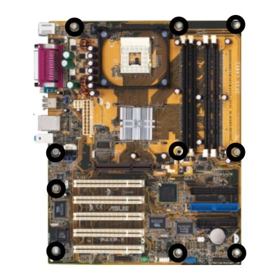
Place ten (10) screws into the holes indicated by circles to secure the motherboard to the chassis. Do not overtighten the screws! Doing so may damage the motherboard. Place this side towards the rear of the chassis ASUS P4XP-X motherboard user guide... -
Page 20: Overview
1.8.1 Overview The motherboard comes with a DIP-type 478-pin Zero Insertion Force (ZIF) socket. The socket is designed for the Intel ® Pentium ® 4 Processor in the 478-pin package with 512KB L2 cache on 0.13 micron process. This processor supports 533/ 400MHz front side bus (FSB), and allows data transfer rates up to 4.2GB/s or 3.2GB/s. -
Page 21: System Memory
PC1600 DIMMs. The SDR sockets support up to 2GB system memory using 168-pin unbuffered non-ECC PC133/PC100 DIMMs. The following figure illustrates the location of the DIMM sockets. 104 Pins 80 Pins ® P4XP-X P4XP-X 184-Pin DDR DIMM Sockets 88 Pins 60 Pins ® P4XP-X 20 Pins P4XP-X 168-Pin DIMM Sockets DDR and SDR DIMM slots cannot be used simultaneouly. -
Page 22: Memory Configurations
1.9.1 Memory configurations Install either DDR DIMMs or SDR DIMMS in any of the following combinations. DO NOT mix DDR and SDR in any configuration! DIMM Location 168-pin DIMM Total Memory DDR Socket 1 64MB, 128MB, 256MB, 512MB, 1GB x1 = DDR Socket 2 64MB, 128MB, 256MB, 512MB, 1GB x1 =... -
Page 23: Standard Interrupt Assignments
When using PCI cards on shared slots, ensure that the drivers support “Share IRQ” or that the cards do not need IRQ assignments. Otherwise, conflicts arise between the two PCI groups making the system unstable and the card inoperable. ASUS P4XP-X motherboard user guide 1-13... -
Page 24: Jumpers
+5VSB (Default) ® P4XP-X P4XP-X USB Device Wake Up 2. Clear RTC RAM (CLRTC1) This jumper allows clearing the Real Time Clock (RTC) RAM in CMOS. You can clear the CMOS memory of date, time, and system setup information by erasing the CMOS RTC RAM data. - Page 25 NOTE: Orient the red markings on P4XP-X the floppy ribbon cable to PIN 1. P4XP-X Floppy Disk Drive Connector 2. Chassis intrusion connector (4-1 pin CHASSIS) This lead is for a chassis designed with intrusion detection feature. This requires an external detection mechanism such as a chassis intrusion sensor or microswitch.
- Page 26 4. Internal audio connectors (4-pin CD1, AUX1) (on audio models only) These connectors allow you to receive stereo audio input from sound sources such as a CD-ROM, TV tuner, or MPEG card. AUX1 (White) CD1 (Black) ® P4XP-X P4XP-X Internal Audio Connectors 1-16 Chapter 1: Product introduction...
- Page 27 6. SMBus connector (6-1 pin SMB1) This connector allows you to connect SMBus (System Management Bus) devices. Devices communicate with an SMBus host and/or other SMBus devices using the SMBus interface. SMB1 ® P4XP-X P4XP-X SMBus Connector ASUS P4XP-X motherboard user guide 1-17...
- Page 28 CPU_FAN1 CHA_FAN1 ® P4XP-X P4XP-X 12-Volt Cooling Fan Power 8. GAME/MIDI connector (16-1 pin GAME1) This connector supports a GAME/MIDI module. Connect an optional GAME/MIDI cable to this connector. The GAME/MIDI port on the module connects a joystick or a game pad for playing games, and MIDI devices for playing or editing audio files.
- Page 29 10. Front panel audio connector (10-1 pin FP_AUDIO1) (on audio models only) This is an interface for the Intel front panel audio cable that allow convenient connection and control of audio devices. FP_AUDIO1 ® P4XP-X P4XP-X Front Panel Audio Connector ASUS P4XP-X motherboard user guide 1-19...
-
Page 30: Connectors
P4XP-X SMI Lead Switch* Requires an ATX power supply. P4XP-X System Panel Connectors • System Power LED Lead (3-1 pin PLED) This 3-1 pin connector connects to the system power LED. The LED lights up when you turn on the system power, and blinks when the system is in sleep mode. -
Page 31: Chapter 2: Bios Information
Chapter 2 This chapter tells how to change system settings through the BIOS Setup menus. Detailed descriptions of the BIOS parameters are also provided. BIOS information... -
Page 32: Managing And Updating Your Bios
BIOS later. 2.1.1 Using ASUS EZ Flash to update the BIOS The ASUS EZ Flash feature allows you to easily update the BIOS without having to go through the long process of booting from a diskette and using a DOS-based utility. - Page 33 5. At the prompt, “Please Enter File Name for NEW BIOS: _”, type in the BIOS file name that you downloaded from the ASUS website, then press <Enter>. EZ Flash will automatically access drive A to look for the file name that you typed.
-
Page 34: Using Aflash To Update The Bios
2.1.2 Using AFLASH to update the BIOS Creating a bootable disk AFLASH.EXE is a Flash Memory Writer utility that updates the BIOS by uploading a new BIOS file to the programmable flash ROM on the motherboard. This file works only in DOS mode. To determine the BIOS version of your motherboard, check the last four numbers of the code displayed on the upper left-hand corner of your screen during bootup. -
Page 35: Updating The Bios
BIOS revision will solve your problems. Careless updating may result to more problems with the motherboard! 1. Download an updated ASUS BIOS file from the Internet (WWW or FTP) (see ASUS CONTACT INFORMATION on page viii for details) and save to the boot floppy disk you created earlier. - Page 36 BIOS file you saved to the boot disk. If the Flash Memory Writer utility is not able to successfully update a complete BIOS file, the system may not boot. If this happens, call the ASUS service center for support.
-
Page 37: Crashfree Bios 2
CrashFree BIOS 2 auto recovery tool allows you to boot the computer using the motherboard bootable support CD or a bootable floppy disk, and update the BIOS using AFLASH.EXE, EZ Flash, or ASUS Live Update utility in case the original BIOS fails or gets corrupted. -
Page 38: Bios Beep Codes
The recovered BIOS may not be of the same version as the original BIOS. Visit ASUS website (www.asus.com) to download the latest BIOS for this motherboard, and update the BIOS using ASUS AFLASH.EXE, ASUS EZ Flash Utility, or ASUS Live Update. -
Page 39: Bios Setup Program
Use this menu to exit the current menu or to exit the Setup program. To access the menu bar items, press the right or left arrow key on the keyboard until the desired item is highlighted. ASUS P4XP-X motherboard user guide... -
Page 40: Legend Bar
2.2.2 Legend bar At the bottom of the Setup screen is a legend bar. The keys in the legend bar allow you to navigate through the various setup menus. The following table lists the keys found in the legend bar with their corresponding functions. Navigation Key(s) Function Description <F1>... -
Page 41: Main Menu
Valid values for month, day, and year are Month: (1 to 12), Day: (1 to 31), Year: (up to 2099). Use the <Tab> or <Shift> + <Tab> keys to move between the month, day, and year fields. ASUS P4XP-X motherboard user guide 2-11... - Page 42 Legacy Diskette A [1.44M, 3.5 in.] Sets the type of floppy drive installed. Configuration options: [None] [360K, 5.25 in.] [1.2M , 5.25 in.] [720K , 3.5 in.] [1.44M, 3.5 in.] [2.88M, 3.5 in.] Floppy 3 Mode Support [Disabled] This is required to support older Japanese floppy drives. The Floppy 3 Mode feature allows reading and writing of 1.2MB (as opposed to 1.44MB) on a 3.5-inch diskette.
-
Page 43: Primary And Secondary Master/Slave
[User Type HDD] Manually enter the number of cylinders, heads and sectors per track for the drive. Refer to the drive documentation or on the drive label for this information. ASUS P4XP-X motherboard user guide 2-13... - Page 44 After entering the IDE hard disk drive information into BIOS, use a disk utility, such as FDISK, to partition and format new IDE hard disk drives. This is necessary so that you can write or read data from the hard disk. Make sure to set the partition of the Primary IDE hard disk drives to active.
-
Page 45: Keyboard Features
IDE devices. Set to [Disabled] to suppress Ultra DMA capability. To make changes to this field, set the Type field to [User Type HDD]. Configuration options: [0] [1] [2] [3] [4] [5] [Disabled] 2.3.2 Keyboard Features ASUS P4XP-X motherboard user guide 2-15... -
Page 46: Advanced Menu
Boot Up NumLock Status [On] This field enables users to activate the Number Lock function upon system boot. Configuration options: [Off] [On] Keyboard Auto-Repeat Rate [12/Sec] This controls the speed at which the system registers repeated keystrokes. Options range from 6 to 30 characters per second. Configuration options: [6/Sec] [8/Sec] [10/Sec] [12/Sec] [15/Sec] [20/Sec] [24/Sec] [30/Sec] Keyboard Auto-Repeat Delay [1/4 Sec] This field sets the time interval for displaying the first and second characters. - Page 47 When the CPU VCore Setting parameter above is set to [Manual], the CPU VCore item allows you to select a specific CPU core voltage. This field is not accessible when the CPU VCore Setting is set to [Auto]. ASUS P4XP-X motherboard user guide 2-17...
- Page 48 Configuration options: [Disabled] [Enabled] ON/OFF PLAY/PAUSE STOP/EJECT PREVIOUS NEXT VOL. DOWN VOL. UP Instant Music CDROM [ASUS CD-ROM] This item displays the detected CD-ROM installed in the system. 2-18 Chapter 2: BIOS information...
-
Page 49: Chip Configuration
This item controls the drive strength of the DDR SDRAM clock signal for an x16 device. It is recommended to keep the default setting for stable system operation. Configuration options: [0.75x] [1.00x] [1.25x] [1.50x] [2.00x] [2.50x] [3.00x] [4.00x] ASUS P4XP-X motherboard user guide 2-19... - Page 50 CKx8 Strength Control [2.00x] This item controls the drive strength of the DDR SDRAM clock signal for an x8 device. It is recommended to keep the default setting for stable system operation. Configuration options: [0.75x] [1.00x] [1.25x] [1.50x] [2.00x] [2.50x] [3.00x] [4.00x] DQ DQS Strength Control [2.00x] This item controls the drive strength of the DDR SDRAM signals DQ and DQS.
-
Page 51: I/O Device Configuration
[Auto] allows the BIOS to detect whether you are using any audio device. If an audio device is detected, the onboard audio controller is enabled; if no audio device is detected, the controller is disabled. Configuration options: [Disabled] [Auto] ASUS P4XP-X motherboard user guide 2-21... -
Page 52: Pci Configuration
Onboard Game Port [200H-207H] This field sets the I/O address for the game port. Configuration options: [Disabled] [200H-207H] [208H-20FH] Onboard MIDI I/O [Disabled] This field sets the I/O address for the MIDI I/O port. Configuration options: [Disabled] [330H-331H] [300H-301H] 2.4.3 PCI Configuration Slot 1, Slot 2, Slot 3 IRQ [Auto] These fields automatically assign the IRQ for each PCI slot. -
Page 53: Pci Irq Resource Exclusion
NOT required by a legacy ISA card. Set the IRQ field to [Yes] if you install a legacy ISA card that requires a unique IRQ and you are NOT using ICU. Configuration options: [No/ICU] [Yes] ASUS P4XP-X motherboard user guide 2-23... -
Page 54: Power Menu
Power Menu The Power menu allows you to reduce power consumption. This feature turns off the video display and shuts down the hard disk after a period of inactivity. Power Management [User Defined] This field allows you to activate or deactivate the automatic power saving features. When set to [Disabled], the power management features do not function regardless of the other settings on this menu. - Page 55 4 seconds puts the system in sleep mode. Regardless of the setting, holding the ATX switch for more than 4 seconds powers off the system. Configuration options: [Soft off] [Suspend] ASUS P4XP-X motherboard user guide 2-25...
-
Page 56: Power Up Control
2.5.1 Power Up Control AC PWR Loss Restart [Disabled] This allows you to set whether or not to reboot the system after power interruptions. [Disabled] leaves your system off while [Enabled] reboots the system. [Previous State] sets the system back to the state it was before the power interruption. -
Page 57: Hardware Monitor
If any of the monitored items is out of range, the following error message appears: “Hardware Monitor found an error. Enter Power setup menu for details”. You will then be prompted to “Press F1 to continue or DEL to enter SETUP”. ASUS P4XP-X motherboard user guide 2-27... -
Page 58: Boot Menu
Boot Menu Boot Sequence The Boot menu allows you to select among the four possible types of boot devices listed using the up and down arrow keys. By using the <+> or <Space> key, you can promote devices and by using the <-> key, you can demote devices. Promotion or demotion of devices alters the priority which the system uses to search for a boot device on system power up. -
Page 59: Exit Menu
Setup. Select Exit from the menu bar to display the following menu. Pressing <Esc> does not immediately exit this menu. Select one of the options from this menu or <F10> from the legend bar to exit. ASUS P4XP-X motherboard user guide 2-29... -
Page 60: Load Setup Defaults
Exit & Save Changes Once you are finished making your selections, choose this option from the Exit menu to ensure the values you selected are saved to the CMOS RAM. The CMOS RAM is sustained by an onboard backup battery and stays on even when the PC is turned off. -
Page 61: Chapter 3: Software Support
Chapter 3 This chapter describes the contents of the support CD that comes with the motherboard package. Software support... -
Page 62: Install An Operating System
The contents of the support CD are subject to change at any time without notice. Visit the ASUS website for updates. 3.2.1 Running the support CD To begin using the support CD, simply insert the CD into your CD-ROM drive. The CD automatically displays the Drivers menu if Autorun is enabled in your computer. -
Page 63: Drivers Menu
SoundMAX Integrated Audio icon 6-channel audio settings. VIA Rhine Family LAN Driver This item installs the Fast Ethernet network driver. 3.2.3 Utilities menu The Utilities menu shows the applications and other software that the motherboard supports. ASUS P4XP-X motherboard user guide... -
Page 64: Asus Contact Information
Install ASUS Update This program allows you to download the latest version of the BIOS from the ASUS website. Before using the ASUS Update, make sure that you have an Internet connection so you can connect to the ASUS website.
Need help?
Do you have a question about the P4XP-X and is the answer not in the manual?
Questions and answers