Advertisement
Advertisement
Table of Contents

Subscribe to Our Youtube Channel
Related Manuals for Asus P4SD - 865GV Socket 478 mATX Motherboard


Summary of Contents for Asus P4SD - 865GV Socket 478 mATX Motherboard
- Page 1 P4SD-LA ( Oxford ) User Guide...
-
Page 2: Table Of Contents
Contents P4SD-LA specifications summary ..........iii Motherboard layout ............... 1 Central Processing Unit (CPU) ..........2 System memory ..............3 Memory configurations ............3 Installing a DIMM ..............4 Expansion slots ..............5 Standard interrupt assignments ..........5 IRQ assignments for this motherboard ........5 PCI slots ................ -
Page 3: P4Sd-La Specifications Summary
Audio RealTek ALC650 6-channel audio CODEC Realtek 8101L 10/100 Mbps Fast Ethernet controller Special features Power Loss Restart ASUS EZ Flash Rear panel I/O 1 x Parallel port 1 x Serial port 1 x Video port 1 x PS/2 keyboard port 1 x PS/2 mouse port 4 x USB 2.0/USB 1.1 ports... -
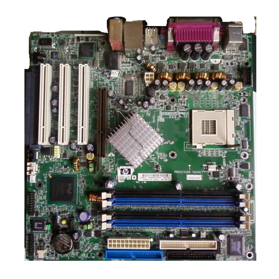
Page 5: Motherboard Layout
Center:Line Out Below:Mic In CHA_FAN1 Accelerated Graphics Port (AGP8X1) PCI 1 Realtek RTL8101L Intel PCI 2 ICH5 FRONT MICIN Chipset SPDI/F PCI 3 Audio TI43AB22A Codec 1394 BIOS SPEAKER OUT CD_IN AUX 1394 FRONT HP-OUT HPANEL USB2 USB1 ASUS P4SD-LA motherboard... -
Page 6: Central Processing Unit (Cpu)
CPU. The lever clicks on the side tab to indicate that it is locked. 6. Install a CPU heatsink and fan following the instructions that came with the heatsink package. 7. Connect the CPU fan cable to the CPU_FAN1 connector on the motherboard. ASUS P4SD-LA motherboard... -
Page 7: System Memory
2. Install only identical (the same type and size) DDR DIMM pairs using the recommended configurations. 3. Make sure that the memory frequency matches the CPU FSB (Front Side Bus). Refer to Table 2 below. 4. Double-sided 16-bit DDR DIMMs are not supported on this motherboard. ASUS P4SD-LA motherboard... -
Page 8: Installing A Dimm
2. Align a DIMM on the socket such that the notch on the DIMM matches the break on the socket. 3. Firmly insert the DIMM into the socket until the retaining clips snap back in place and the DIMM is properly seated. Unlocked Retaining Clip ASUS P4SD-LA motherboard... -
Page 9: Expansion Slots
— — — — — shared Onboard LAN — — — shared — — — — Onboard audio — used — — — — — — Onboard 1394 controller — — — — — shared — — ASUS P4SD-LA motherboard... -
Page 10: Pci Slots
Note the notches on the card golden fingers to ensure that they fit the AGP slot on your motherboard. Install only +0.8V/+1.5V AGP cards on this motherboard! AGP Card without Retention Notch P4SD-LA Accelerated Graphics Port (AGP8X) ASUS P4SD-LA motherboard... -
Page 11: Jumper
4. Hold down the <Del> key during the boot process and enter BIOS setup to re-enter data. Except when clearing the RTC RAM, never remove the cap on jumper J19 default position. Removing the cap will cause system boot failure! Clear CMOS Normal P4SD-LA Clear RTC RAM (Default) ASUS P4SD-LA motherboard... -
Page 12: Connectors
ATX12V1 ATXPWR1 +12.0VDC +5.0VDC +12V DC +12V DC +5VSB +5.0VDC PWR_OK -5.0VDC +5.0VDC +5.0VDC PS_ON# +3.3VDC -12.0VDC +3.3VDC +3.3VDC P4SD-LA ATX Power Connector ASUS P4SD-LA motherboard... - Page 13 2. The hole near the blue connector on the UltraDMA/100/66 cable is intentional. NOTE: Orient the red markings (usually zigzag) on the IDE ribbon cable to PIN 1. PIN 1 P4SD-LA IDE Connectors PIN 1 ASUS P4SD-LA motherboard...
- Page 14 1394 module. Attach the 10-1 pin cable plug to this connector, and the 6-pin cable plug to the 1394 module. You may also connect a 1394-compliant internal hard disk to this connector. 1394 P4SD-LA IEEE-1394 Connectors ASUS P4SD-LA motherboard...
- Page 15 7. Speaker out connector (5-1 pin SPEAKER OUT) This connector is for an optional audio module. Connect one end of the audio cable to this connector and the other end to the audio module. SPEAKER OUT P4SD-LA Speaker Out Connector ASUS P4SD-LA motherboard...
- Page 16 9. Microphone connector (3-pin FRONT MICIN) This connector is for a chassis-mounted front panel microphone jack. Use a 3-pin audio cable to connect the microphone jack to this connector. FRONT MICIN MIC Power MIC Input Ground P4SD-LA ront Microphone Connector ASUS P4SD-LA motherboard...
- Page 17 This connector is for an S/PDIF audio module that allows digital instead of analog sound output. Connect one end of the audio cable to this connector and the other end to the S/PDIF module. SPDI/F SPDIFOUT Ground P4SD-LA Digital Audio Interface ASUS P4SD-LA motherboard...
- Page 18 ON mode for more than 4 seconds turns the system OFF. • Reset Switch Lead (2-pin RESET) This 2-pin connector connects to the case-mounted reset switch for rebooting the system without turning off the system power. ASUS P4SD-LA motherboard...
Need help?
Do you have a question about the P4SD - 865GV Socket 478 mATX Motherboard and is the answer not in the manual?
Questions and answers