
Subscribe to Our Youtube Channel
Related Manuals for Acoustic Research HT60


Summary of Contents for Acoustic Research HT60
- Page 1 HT60.book Page i Monday, April 2, 2007 6:28 PM HT60 Installation and Operation Manual Manual de la instalación y de la operación Manuel d'installation et d'opération...
-
Page 2: Table Of Contents
HT60.book Page i Monday, April 2, 2007 6:28 PM HT60 Contents Important Safety Instructions ................ 1 Introduction ....................3 Surround System Configuration ..............5 Connecting the Subwoofer................6 Subwoofer/Preamp Controls & Connections ..........7 Installing your Surround Speakers..............9 Specifications....................10 Home Audio 5 Year Limited Warranty ............ - Page 3 HT60.book Page ii Monday, April 2, 2007 6:28 PM page ii...
-
Page 4: Important Safety Instructions
Important Safety Instructions Read these instructions. Keep these instructions. Heed all warnings. Follow all instructions. Do not use this apparatus near water. Clean only with dry cloth. Do not block any ventilation openings. Install in accordance with the manufacturer’s instructions. Do not install near any heat sources such as radiators, heat registers, stoves, or other apparatus (including amplifiers) that produce heat. - Page 5 20. The ventilation should not be impeded by covering the ventilation openings with items, such as newspapers, table-cloths, curtains, etc. 21. No naked flame sources, such as lighted candles, should be placed on the apparatus. 22. The apparatus should be used in moderate climate. 23.
- Page 6 HT60.book Page 2 Monday, April 2, 2007 6:28 PM The lightning flash with arrowhead symbol within an equilateral tri- angle is intended to alert the user to the presence of “dangerous volt- age” within the product’s enclosure that may be of significant magnitude to constitute a risk of electrical shock to persons.
-
Page 7: Introduction
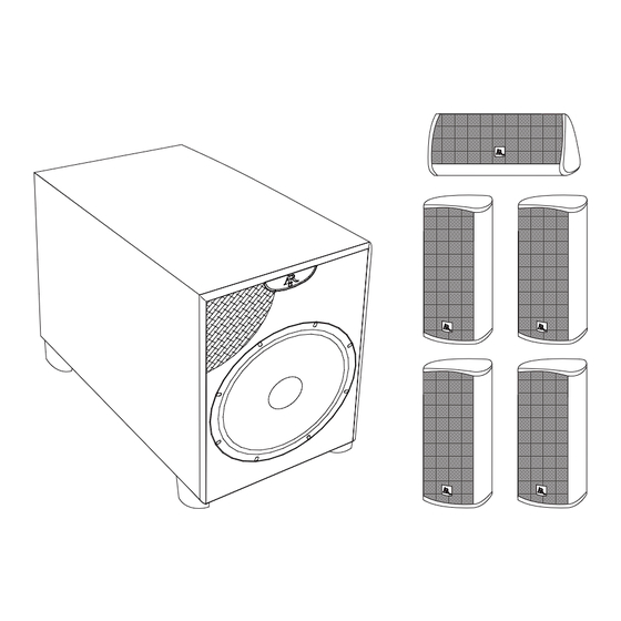
HT60.book Page 3 Monday, April 2, 2007 6:28 PM HT60 Introduction NOTE: Check your system immediately. If it has been damaged in transit, re- port the damage immediately by calling your AR dealer. Please follow the directions in this manual to achieve the best performance from your system. - Page 8 HT60.book Page 4 Monday, April 2, 2007 6:28 PM FIGURE 1 - Parts Reference SURROUND SPEAKERS (x 4) CENTER CHANNEL SPEAKER (x 1) SUBWOOFER (x1) page 4...
-
Page 9: Surround System Configuration
HT60.book Page 5 Monday, April 2, 2007 6:28 PM HT60 Surround System Configuration The optimum listening position is at the tip of the “stereo triangle.” The equilibrium between the right and left stereo channels is best in this position, providing the most balanced and realistic sound reproduction. -
Page 10: Connecting The Subwoofer
HT60.book Page 6 Monday, April 2, 2007 6:28 PM Connecting the Subwoofer IMPORTANT: To avoid damaging your equipment, make sure the subwoofer and all components are turned off before making any connections. Subwoofer Placement Placement of your subwoofer will dramatically affect its performance. Your AR sub- woofer is designed to work best when placed on the floor within 15 feet of your front speakers. -
Page 11: Subwoofer/Preamp Controls & Connections
HT60.book Page 7 Monday, April 2, 2007 6:28 PM HT60 Subwoofer/Preamp Controls & Connections The amplifier and subwoofer controls are located on the back of the subwoofer cabinet, shown in Figure 3. FIGURE 3 - Subwoofer/Preamp Controls & Connections page 7... - Page 12 HT60.book Page 8 Monday, April 2, 2007 6:28 PM • Power cord: Plug the power cord into an AC wall outlet. • MODE (AUTO ON/OFF): Move this switch to turn the AC supply OFF/ ON. When AUTO ON is selected, the Subwoofer remains in the stand-by mode until an audio signal is detected.
-
Page 13: Installing Your Surround Speakers
HT60.book Page 9 Monday, April 2, 2007 6:28 PM HT60 Installing your Surround Speakers The surround speakers are identical and can be used for any channel. Surround Speaker Placement Speaker placement is critical, and can make the difference between good and great sound quality. -
Page 14: Specifications
HT60.book Page 10 Monday, April 2, 2007 6:28 PM Specifications Surround Speakers: Driver Complement: 2 Way Satellite Woofer (2) 3" Treated Cellulose (Magnetically Shielded) Tweeter 1/2” PEI dome (Magnetically Shielded) Frequency Response: 100Hz – 20,000Hz (+/–3db) Recommended Amplifier Power: 15 – 100 watts Sensitivity: 91dB Nominal Impedance: 8 ohms Finish: Extruded Aluminum... -
Page 15: Home Audio 5 Year Limited Warranty
How to Obtain Service Please contact us at 800-225-9847 or write to: Acoustic Research (Attention: Customer Service Department), AB Tech Services, 17C Airport Drive, Hopedale, MA 01747 page 11... - Page 16 HT60.book Page 12 Monday, April 2, 2007 6:28 PM page 12...
-
Page 17: Instrucciones De Seguridad Importantes
HT60.book Page 13 Monday, April 2, 2007 6:28 PM HT60 Instrucciones de Seguridad Importantes • Lea estas instrucciones. • Mantenga éstas instrucciones en un lugar seguro. • Preste atención a todas las instrucciones. • Siga todas las instrucciones. • No utilice este aparato cerca del agua. •... - Page 18 HT60.book Page 14 Monday, April 2, 2007 6:28 PM La luz centellante con el símbolo de cabeza de flecha, dentro de un triángulo equilátero, intenta alertar al usuario de la presencia de un "voltaje peligroso" dentro del producto de tal magnitud que sig- nifique un riesgo de choque eléctrico a las personas.
-
Page 19: Introducción
HT60.book Page 15 Monday, April 2, 2007 6:28 PM HT60 Introducción NOTA: Verifique inmediatamente su sistema. Si ha sido dañado en tránsito, re- porte el daño inmediatamente llamando a su distribuidor AR. Por favor siga las instrucciones de este manual para lograr el mejor desempeño de su sistema. - Page 20 HT60.book Page 16 Monday, April 2, 2007 6:28 PM FIGURA 1 - Referencia de las Piezas ALTAVOCES SURROUND (x 4) ALTAVOZ DE CENTRO (x 1) SUBWOOFER (x 1) page 16...
-
Page 21: Configuración Del Sistema Surround
HT60.book Page 17 Monday, April 2, 2007 6:28 PM HT60 Configuración del Sistema Surround La posición de escucha óptima es en la punta de un "triángulo estéreo". El equilibrio entre canales estéreos derecho e izquierda es mejor en esta posición, brindando la re- producción de sonido más balanceada y realista. -
Page 22: Conectando El Altavoz De Graves O Subwoofer
HT60.book Page 18 Monday, April 2, 2007 6:28 PM Conectando el Altavoz de Graves o Sub- woofer IMPORTANTE: Para evitar dañar su equipo, asegúrese que el altavoz de graves y todos los componentes estén apagados antes de realizar alguna con- exión. - Page 23 HT60.book Page 19 Monday, April 2, 2007 6:28 PM HT60 de altavoz hasta dejar los conductores pelados antes de conectar a un altavoz, altavoz de graves o receptor. Siempre conecte el terminal rojo (+) en el recep- tor, al terminal rojo (+) en el Altavoz de Graves, y conecte el terminal negro (-) en el receptor, al terminal negro (-) en el Altavoz de Graves.
-
Page 24: Controles Y Conexiones De Altavoz De Graves/Preamplificador
HT60.book Page 20 Monday, April 2, 2007 6:28 PM Controles y Conexiones de Altavoz de Graves/Preamplificador The amplifier and subwoofer controls are located on the back of the subwoofer cabinet, shown in Figure 3. FIGURA 3 - Controles y Conexiones de Altavoz de Graves/Preamplificador page 20... - Page 25 HT60.book Page 21 Monday, April 2, 2007 6:28 PM HT60 • Cable de energía: Enchufe el cable de energía a una toma de corriente alterna en la pared. • MODE (AUTO ON/OFF): Mueva esta llave para apagar o encender (OFF/ ON) la alimentación de corriente alterna.
-
Page 26: Instalando Sus Altavoces Surround
HT60.book Page 22 Monday, April 2, 2007 6:28 PM Instalando sus Altavoces Surround Los altavoces surround son idénticos y se pueden usar para cualquier canal. Ubicación del Altavoz Surround La ubicación del altavoz es crítica y puede marcar la diferencia entre una buena o una excelente calidad de sonido. -
Page 27: Especificaciones
HT60.book Page 23 Monday, April 2, 2007 6:28 PM HT60 Especificaciones Altavoces Surround: Complemento del Controlador: Satélite de 2 Vías Altavoz de Graves (2) con 3" de Tratamiento con Celulosa (Protegido Magnética- mente) Altavoz de Agudo con cúpula PEI de 1/2" (Protegido Magnéticamente) Frecuencia de Respuesta 100Hz - 20.000Hz (+/-3db) Energía para el Amplificador Recomendada: 15 - 100 wats Sensibilidad: 91dB... -
Page 28: Garantía Limitada De 5 Años De Home Audio
HT60.book Page 24 Monday, April 2, 2007 6:28 PM Garantía Limitada de 5 Años de Home Audio Audiovox Electronics Corp (la Compañía); garantiza al comprador minorista original de este producto, siempre que el mismo hubiera sido comprado en un distribuidor AR autorizado, que si este producto o cualquier parte del mismo (excepto como se detalla abajo) bajo usos y condiciones normales se pruebe defectuoso en material o mano de obra dentro de los 5 años de la fecha original de compra, tales defectos serán reem-... -
Page 29: Instructions De Securite Importantes
HT60.book Page 25 Monday, April 2, 2007 6:28 PM HT60 Instructions de Securite Importantes • Lisez ces instructions. • Gardez ces instructions dans un endroit sûr. • Faites attention à tous les avertissements. • Suivez toutes les instructions. • N'utilisez pas l'appareil près de l'eau. •... - Page 30 HT60.book Page 26 Monday, April 2, 2007 6:28 PM La foudre avec le symbole tête de flèche, à l'intérieur d'un triangle équilatéral, avertit l'utilisateur quant à la présence du « voltage dan- gereux » à l'intérieur de l'énclos du produit zui peut être d'une gran- deur suffisante pour constituer un risque de choc électrique à...
-
Page 31: Introduction
HT60.book Page 27 Monday, April 2, 2007 6:28 PM HT60 Introduction A noter : Vérifiez votre système immédiatement. S'il a été endommagé en tran- sit, rapportez-le immédiatement en appelant votre détaillant AR. Veuillez suivre les directions dans ce guide pour obtenir la meilleure performance de votre système. - Page 32 HT60.book Page 28 Monday, April 2, 2007 6:28 PM DIAGRAMME 1 - Référence De Pièces Haut parleurs quadriphoniques (x 4) Haut parleur central (x 1) Subwoofer (x 1) page 28...
-
Page 33: Configuration Du Systeme Quadriphonique
HT60.book Page 29 Monday, April 2, 2007 6:28 PM HT60 Configuration du systeme quadriphonique La position d'écoute optimal est le bout du « stéréo triangle ». L'équilibre entre les chaînes droite et gauche stéréo est le meilleur dans cette position, fournissant la repro- duction du son le mieux équilibré... -
Page 34: Branchez Le Caisson De Basse
HT60.book Page 30 Monday, April 2, 2007 6:28 PM Branchez le caisson de basse Important : Pour éviter d'endommager votre équipement, assurez-vous que le caisson de basse et tous les autres composants sont mis en arrêt avant de faire les connexions. Emplacement du caisson de basse L'emplacement de votre caisson de basse va affecter sa performance d'une manière dramatique. - Page 35 HT60.book Page 31 Monday, April 2, 2007 6:28 PM HT60 de basse ou récepteur. Branchez toujours la borne rouge (+) sur le récepteru à la borne rouge (+) sur le caisson de basse, et la borne noire (-) sur le récep- teur à...
-
Page 36: Caisson De Basse/Connexions Et Contrôles Pré-Amplificateur
HT60.book Page 32 Monday, April 2, 2007 6:28 PM Caisson de basse/Connexions et Contrôles pré-amplificateur L'amplificateur et les contrôles caisson de basse sont situés au dos du cabinet du cais- son de basse, comme montré dans la Figure 3. FIGURE 3 - Caisson de basse/Connexions et Contrôles pré-amplificateur page 32... - Page 37 HT60.book Page 33 Monday, April 2, 2007 6:28 PM HT60 • Câbles d'alimentation : Branchez le câble d'alimentation à une prise de courant murale. • MODE (AUTO ON/OFF) : Utilisez cet interrupteur pour mettre le courant AC en marche et en arrêt. Lors que AUTO ON est sélectionné, le caisson de basse reste dans la mode en attente jusqu'à...
-
Page 38: Installez Vos Hauts Parleurs Quadriphoniques
HT60.book Page 34 Monday, April 2, 2007 6:28 PM Installez vos hauts parleurs quadripho- niques Les hauts parleurs quadriphoniques sont identique et peuvent être utilisé pour n'im- porte quelle chaîne. Emplacement des hauts parleurs quadriphoniques L'emplacement des hauts parleurs est critique et peut être la différence entre une bonne qualité... -
Page 39: Spécifications
HT60.book Page 35 Monday, April 2, 2007 6:28 PM HT60 Spécifications Hauts Parleurs Quadriphoniques Complément de pilote : Satellite 2voie Caisson de basse (2) 3'' Cellulose Traité (Protégé avec magnétiquement) Haut parleur d'aigu ½'' Dôme PEI (Protégé magnétiquement) Réponse fréquence : 100Hz - 20000Hz (+/- 3dB) Puissance d'amplificateur recommandée : 15 à... -
Page 40: Audio À La Maison Garantie Limitée De 5 Ans
HT60.book Page 36 Monday, April 2, 2007 6:28 PM Audio à la maison Garantie limitée de 5 ans Audiovox Electronics Corporation (la Société) garantit à l'acheteur d'origine de ce pro- duit qui a été acheté d'un détaillant AR autorisé que si ce produit ou une partire quelconque de ce produit (sauf spécifié... - Page 41 HT60.book Page 37 Monday, April 2, 2007 6:28 PM HT60 page 37...
- Page 42 HT60.book Page 38 Monday, April 2, 2007 6:28 PM Audiovox Electronics Corporation 150 Marcus Blvd Hauppauge, New York 11788 © 2007 Audiovox Electronics Corporation Acoustic Research is a registered trademark of Audiovox Electronics Corporation. PRINTED IN CHINA. www.acoustic-research.com page 38...
- Page 43 WHT24 Important Safety Instructions • Read these instructions. • Keep these instructions in a safe place. • Heed all warnings. • Follow all instructions. • Do not use this apparatus near water. • Clean only with a dry cloth. • Do not block any ventilation openings.
- Page 44 The lightning flash with arrowhead symbol within an equilateral tri- angle is intended to alert the user to the presence of “dangerous volt- age” within the product’s enclosure that may be of significant magnitude to constitute a risk of electrical shock to persons. The exclamation point within an equilateral triangle is intended to alert the user to the presence of important operating and maintenance (servicing) instructions in the literature accompanying this product.
- Page 45 WHT24 Introduction NOTE: Check your system immediately. If it has been damaged in transit, re- port the damage immediately by calling your AR dealer. The WHT24 wireless speaker system consists of a transmitter and two receivers that provide two independent audio channels and a quality-of-service channel that guaran- tees interference-free, uncompressed, full CD quality sound.
- Page 46 FIGURE 1 - Parts Reference ON OFF AUDIO DC IN LINK . Receiver (x 2) . Adjustable Spike Feet (x 8) . Metal Holder for Spike Feet (x 8) . Threaded Bottom Pole (x 2) . Upper/Top Pole (x 2) .
- Page 47 WHT24 Installing the Adjustable Spike Feet 1. Turn the receiver over, being careful not to scratch the top surface. 2. Turn hex nut to adjust spiked foot to desired height. 3. Insert threaded spike foot into one of the specified holes in the base of the receiver.
- Page 48 Assembling the Wireless Speaker Stand The speaker stand comes in two FIGURE 4 - Speaker parts, with the speaker wire already Stand Assembly threaded through both poles. Please be careful when unpacking to ensure that the wire remains threaded dur- HT60 ing assembly.
- Page 49 WHT24 Connecting your Speakers The WHT24 wireless receivers are identical and can be used for either rear channel. 1. Locate the wiring coming from the top of the FIGURE 5 - Connecting speaker stand assembly. Your Speakers 2. Twist the end of each speaker wire. 3.
- Page 50 Remote Receiver Controls & Connections The remote receiver controls and connectors are shown in Figure 6. FIGURE 6 - Remote Receiver Controls & Connections ON OFF ON OFF AUDIO D C I N D C IN LINK • L AUDIO OFF R: Set switch to indicate if the attached speaker will represent the L or R rear surround position or set to AUDIO OFF.
- Page 51 WHT24 Installing the Transmitter 1. The transmitter can be positioned vertically in the stand or it can sit horizontally without the stand, depending on where it will be placed. If using the stand, place the transmitter into the docking stand and secure stand with the attached screw. FIGURE 7 - Attach Transmitter to Docking Stand page 9...
- Page 52 2. Connect the transmitter to your component receiver using either the speaker wire or RCA pre-output connections, being careful to match the wire colors. FIGURE 8 - Connect Transmitter with Speaker Wires HDMI LEFT RIGHT LEFT RIGHT iPOD IN CENTER REAR REAR SURROUND...
- Page 53 WHT24 3. Connect the 6.3VAC power supply adapter labelled “FOR TRANSMITTER.” 4. Plug the transmitter into your power outlet (switched outlet recommended). 5. Turn the transmitter on by pressing the Power on/off button on the back of the transmitter. FIGURE 10 - Connect Power to Your Transmitter POWER BUTTON Link...
- Page 54 Resetting the Channel Using the LINK Switch In the event there is another WHT24 in the vicinity, you can use the LINK switch to change the system address to avoid interference. Normally this is not necessary since the likelihood of another system being within radio range is rare. To determine the presence of another WHT24, perform the following steps: 1.
- Page 55 WHT24 NOTE: If you inadvertently slide the LINK switch on the transmitter, don't worry; the link address will only be changed if you deliberately press the re- ceiver LINK button while the transmitter LED is blinking. The transmitter LED will simply stop flashing after a minute and nothing will have changed. page 13...
-
Page 56: Troubleshooting
Troubleshooting No Sound A properly connected system will take 5-10 seconds to link upon initial power-on. This is normal. If there is still no sound, follow the steps listed below. 1. Make sure the transmitter input device is connected to the transmitter correctly. 2. - Page 57 WHT24 In the highly unlikely event your neighbor was attempting to re-link at the same time, it is possible to link your system to his. Should this happen, or if you have any doubts, repeat the linking operation. Your system will generate a new, unique address each time it is linked.
- Page 58 How to Obtain Service Please contact us at 800-225-9847 or write to: Acoustic Research (Attention: Customer Service Department), AB Tech Services, 17C Airport Drive, Hopedale, MA 01747 page 16...
Need help?
Do you have a question about the HT60 and is the answer not in the manual?
Questions and answers