Intel DH67GD Product Manual
Desktop board
Hide thumbs
Also See for DH67GD:
- Specification (94 pages) ,
- Specification (7 pages) ,
- Product manual (78 pages)
Table of Contents
Advertisement
Advertisement
Table of Contents

Related Manuals for Intel DH67GD


Summary of Contents for Intel DH67GD
- Page 1 Intel® Desktop Board DH67GD Product Guide Order Number: G13841-001...
-
Page 2: Revision History
Intel may make changes to specifications and product descriptions at any time, without notice. Intel Desktop Board DH67GD may contain design defects or errors known as errata which may cause the product to deviate from published specifications. Current characterized errata are available on request. -
Page 3: Intended Audience
The suitability of this product for other PC or embedded non-PC applications or other environments, such as medical, industrial, alarm systems, test equipment, etc. may not be supported without further evaluation by Intel. Document Organization The chapters in this Product Guide are arranged as follows:... - Page 4 Intel Desktop Board DH67GD Product Guide Terminology The table below gives descriptions of some common terms used in the product guide. Term Description Gigabyte (1,073,741,824 bytes) Gigahertz (one billion hertz) Kilobyte (1024 bytes) Megabyte (1,048,576 bytes) Megabit (1,048,576 bits) Megahertz (one million hertz)
-
Page 5: Table Of Contents
Contents 1 Desktop Board Features Supported Operating Systems................11 Desktop Board Components.................12 Processor......................14 ® Intel H67 Express Chipset .................15 Main Memory.....................15 Graphics Subsystem ...................16 Integrated Graphics ..................16 ® Intel HD Graphics ................16 High-Definition Multimedia Interface* (HDMI*)........16 Digital Visual Interface (DVI-I) ..............17 VGA Displays ..................17... - Page 6 Flash Memory Update Utility or the ISO Image BIOS Update File ..................62 Obtaining the BIOS Update File ..............62 Updating the BIOS with the Intel Flash Memory Update Utility......63 Updating the BIOS with the ISO Image BIOS Update File .........63 Recovering the BIOS ...................64...
- Page 7 22. Location of the Chassis Fan Header ..............50 23. Connecting Power Supply Cables ..............51 24. Location of the BIOS Configuration Jumper Block ..........52 25. Removing the Battery ...................59 26. Intel Desktop Board DH67GD China RoHS Material Self Declaration Table .....72...
- Page 8 2. Intel Desktop Board DH67GD Components ............13 3. Audio Jack Retasking Support.................18 4. LAN Connector LEDs ..................19 5. Front Panel Audio Signal Names for Intel HD Audio..........45 6. Front Panel Audio Header Signal Names for AC ’97 Audio ........45 7. IEEE 1394a Header Signal Names ..............45 8.
-
Page 9: Desktop Board Features
HD Audio) Audio using a Realtek* ALC892 audio codec including: ― Front panel audio header with support for Intel HD Audio and AC ’97 Audio ― Five analog audio jacks on the back panel ― Onboard S/PDIF out header and back panel optical S/PDIF out connector •... - Page 10 Intel Desktop Board DH67GD Product Guide Table 1. Feature Summary (continued) Peripheral USB Support: Interfaces • Two USB 3.0 ports implemented with stacked back panel connectors • Fourteen USB 2.0 ports: ― Six ports implemented with stacked back panel connectors ―...
-
Page 11: Supported Operating Systems
Desktop Board Features Supported Operating Systems The Desktop Board provides full support for the following operating systems: • Microsoft Windows* 7 Ultimate 64-bit edition • Microsoft Windows 7 Ultimate 32-bit edition • Microsoft Windows 7 Home Basic 64-bit edition • Microsoft Windows 7 Home Premium 64-bit edition •... -
Page 12: Desktop Board Components
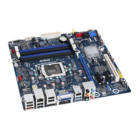
Intel Desktop Board DH67GD Product Guide Desktop Board Components Figure 1 shows the approximate location of the major components on Intel Desktop Board DH67GD. Figure 1. Intel Desktop Board DH67GD Components... - Page 13 Desktop Board Features Table 2. Intel Desktop Board DH67GD Components Label Description Conventional PCI bus connector PCI Express 2.0 x1 add-in card connector IEEE 1394a header PCI Express 2.0 x1 add-in card connector PCI Express 2.0 x16 add-in card connector...
-
Page 14: Processor
Desktop Board may result in damage to the board, or the system may not function properly. Intel Desktop Board DH67GD supports the Intel Core i7, Intel Core i5, and Intel Core i3 processors in an LGA1155 socket. Processors are not included with the Desktop Board and must be purchased separately. -
Page 15: Intel H67 Express Chipset
The Intel H67 Express Chipset, consisting of the Intel H67 Platform Controller Hub (PCH), provides interfaces to the processor and the USB, SATA, LPC, audio, network, display, and PCI Express x1 interfaces. The Intel H67 PCH is a centralized controller for the board’s I/O paths. -
Page 16: Graphics Subsystem
Intel Desktop Board DH67GD Product Guide Graphics Subsystem The board supports system graphics through either Intel HD Graphics or a PCI Express 2.0 x16 add-in graphics card. Integrated Graphics ® The board supports integrated graphics through the Intel Flexible Display Interface (FDI) for processors with Intel HD Graphics. -
Page 17: Digital Visual Interface (Dvi-I)
For more information about DisplayPort technology go to http://www.displayport.org. PCI Express* x16 Graphics The Intel Core i7, Intel Core i5, Intel Core i3, and Intel Pentium processors in an LGA1155 socket support discrete add-in graphics cards via the PCI Express 2.0 x16 add-in card connector. -
Page 18: Audio Subsystem
S/PDIF-out header with support for optical or coaxial S/PDIF output • Front panel audio header with support for Intel HD Audio and AC ’97 Audio Table 3 lists the supported functions of the front panel (FP) and back panel (BP) audio jacks. -
Page 19: Lan Subsystem
Desktop Board Features LAN Subsystem The LAN subsystem includes: • Intel 82579V Gigabit (10/100/1000 Mb/s) Ethernet LAN controller • RJ-45 LAN connector with integrated status LEDs LAN software and drivers are available at http://downloadcenter.intel.com/. Two LEDs are built into the RJ-45 LAN connector located on the back panel (see Figure 2). -
Page 20: Sata Support
USB 3.0 driver support from the operating system. The device driver for the USB 3.0 host controller must be installed from the included Intel Express Installer Driver and Software DVD before it can be operational in the operating system. -
Page 21: Sata Auto Configuration
Desktop Board Features SATA Auto Configuration If you install a SATA device (such as a hard drive) in your computer, the auto- configuration utility in the BIOS automatically detects and configures the device for your computer. You do not need to run the BIOS Setup program after installing a SATA device. -
Page 22: Hardware Management
Fan speed controllers and sensors are integrated into the legacy I/O controller. • Thermal sensors in the processor and Intel H67 PCH, as well as near the processor voltage regulators and system memory. • Monitoring of system voltages to detect levels above or below acceptable values •... -
Page 23: Software Support
Desktop Board Features Software Support ACPI ACPI gives the operating system direct control over the power management and Plug and Play functions of a computer. The use of ACPI with the Desktop Board requires an operating system that provides full ACPI support. Hardware Support Power Connectors ATX12V-compliant power supplies can turn off the computer power through system... -
Page 24: Instantly Available Pc Technology
Intel Desktop Board DH67GD Product Guide Instantly Available PC Technology CAUTION For Instantly Available PC technology, the 5 V standby line for the power supply must be capable of delivering adequate +5 V standby current. Failure to provide adequate standby current when using this feature can damage the power supply and/or effect ACPI S3 sleep state functionality. -
Page 25: Wake From Usb
Figure 3. Location of the Standby Power Indicator For more information on standby current requirements for the Desktop Board, refer to the Technical Product Specification at http://support.intel.com/support/motherboards/desktop/ Wake from USB NOTE Wake from USB requires the use of a USB peripheral that supports Wake from USB and an operating system that supports Wake from USB. -
Page 26: Speaker
Intel Desktop Board DH67GD Product Guide Speaker A speaker is mounted on the Desktop Board. The speaker provides audible error code (beep code) information during the Power-On Self-Test (POST). Refer to Appendix A for a description of the board’s beep codes. -
Page 27: Installing And Replacing Desktop Board Components
2 Installing and Replacing Desktop Board Components This chapter tells you how to: • Install the I/O shield • Install and remove the Desktop Board • Install and remove a processor • Install and remove memory • Install and remove a PCI Express x16 card •... -
Page 28: Installation Precautions
Intel Desktop Board DH67GD Product Guide Installation Precautions When you install and test the Intel Desktop Board, observe all warnings and cautions in the installation instructions. To avoid injury, be careful of: • Sharp pins on connectors • Sharp pins on printed circuit assemblies •... -
Page 29: Installing The I/O Shield
Installing and Replacing Desktop Board Components Installing the I/O Shield The Desktop Board comes with an I/O shield. When installed in the chassis, the shield blocks radio frequency transmissions, protects internal components from dust and foreign objects, and promotes correct airflow within the chassis. Install the I/O shield before installing the Desktop Board in the chassis. -
Page 30: Installing And Removing The Desktop Board
Refer to your chassis manual for instructions on installing and removing the Desktop Board. Figure 5 shows the location of the mounting screw holes for Intel Desktop Board DH67GD. Figure 5. Intel Desktop Board DH67GD Mounting Screw Hole Locations... -
Page 31: Installing And Removing A Processor
Installing and Replacing Desktop Board Components Installing and Removing a Processor Instructions on how to install the processor on the Desktop Board are given below. Installing a Processor CAUTION Before installing or removing a processor, make sure the AC power has been removed by unplugging the power cord from the computer;... -
Page 32: Lift The Load Plate
Intel Desktop Board DH67GD Product Guide 3. Rotate the socket lever to lift the load plate away from the socket (Figure 7, A). Make sure that the load plate is in the fully open position (Figure 7, B) while being careful not to damage adjacent components. -
Page 33: Remove The Processor From The Protective Cover
Installing and Replacing Desktop Board Components 4. Remove the processor from its protective cover. Hold the processor only at the edges, being careful not to touch the bottom of the processor (see Figure 8). NOTE Do not discard the processor cover. Always replace the processor cover if you remove the processor from the socket. -
Page 34: Secure The Load Plate In Place
Intel Desktop Board DH67GD Product Guide 7. Carefully lower the socket lever (Figure 10, A) while making sure that the front edge of the load plate slides under the shoulder screw cap as the lever is lowered. Latch the socket lever under the load plate tab (Figure 10, C, D). The socket cover (Figure 10, B) will pop off as shown. -
Page 35: Installing A Processor Fan Heat Sink
Installing and Replacing Desktop Board Components Installing a Processor Fan Heat Sink Intel Desktop Board DH67GD has mounting holes for a processor fan heat sink. For instructions on how to attach the processor fan heat sink to the Desktop Board, refer to the boxed processor manual or boxed thermal solution manual. -
Page 36: Installing And Removing System Memory
Intel Desktop Board DH67GD Product Guide Installing and Removing System Memory NOTE To be fully compliant with all applicable Intel SDRAM memory specifications, the board requires DIMMs that support the Serial Presence Detect (SPD) data structure. Guidelines for Dual Channel Memory Configuration Desktop board DH67GD has four 240-pin DDR3 DIMM sockets arranged in two channels (A and B). -
Page 37: Three Dimms
Figure 14. Example Dual Channel Memory Configuration with Three DIMMs NOTE Intel Core i7 processors, Intel Core i5 processors, and Intel Core i3 processor series 2000 require memory to be installed in the DIMM 1 (or Channel A, DIMM 1) socket. -
Page 38: Installing Dimms
Intel Desktop Board DH67GD Product Guide Installing DIMMs To make sure you have the correct DIMM, place it on the illustration of the DDR3 DIMM in Figure 15. All the notches should match with the DDR3 DIMM. Figure 15. Use DDR3 DIMMs... -
Page 39: Installing A Dimm
Installing and Replacing Desktop Board Components To install a DIMM, follow these steps: 1. Observe the precautions in "Before You Begin" on page 27. 2. Turn off all peripheral devices connected to the computer. Turn off the computer and disconnect the AC power cord. 3. -
Page 40: Removing Dimms
Intel Desktop Board DH67GD Product Guide Removing DIMMs To remove a DIMM, follow these steps: 1. Observe the precautions in "Before You Begin" on page 27. 2. Turn off all peripheral devices connected to the computer. Turn off the computer. -
Page 41: Installing A Pci Express X16 Graphics Card
Installing and Replacing Desktop Board Components Follow these instructions to install a PCI Express x16 graphics card: 1. Observe the precautions in "Before You Begin" on page 27. 2. Place the card in the PCI Express x16 connector (Figure 17, A) and press down on the card until it is completely seated in the connector and the card retention notch on the card snaps into place around the retention mechanism pin on the connector. -
Page 42: Removing A Pci Express X16 Graphics Card
Intel Desktop Board DH67GD Product Guide Removing a PCI Express x16 Graphics Card Follow these instructions to remove a PCI Express x16 graphics card from a connector: 1. Observe the precautions in "Before You Begin" on page 27. 2. Disconnect the monitor cable from the graphics card back panel connector. -
Page 43: Connecting Sata Drives
Installing and Replacing Desktop Board Components Connecting SATA Drives Use the included SATA cables to connect internal SATA drives. Each cable can be used to connect one internal SATA drive to the Desktop Board’s SATA connectors. The blue SATA connectors support 6.0 Gb/s and slower speed SATA devices while the black SATA connectors support 3.0 Gb/s and slower speed SATA devices. -
Page 44: Connecting To The Internal Headers
Connecting to the Internal Headers Before connecting cables to any of the internal headers, observe the precautions in “Before You Begin” on page 27. Figure 20 shows the location of the internal headers and connectors on Intel Desktop Board DH67GD. Figure 20. Internal Headers... -
Page 45: Front Panel Audio Header
Installing and Replacing Desktop Board Components Front Panel Audio Header The front panel audio header shown in Figure 20, A supports both Intel High Definition (HD) Audio and AC ’97 Audio. Table 5 shows the pin assignments and signal names for HD Audio and Table 6 shows the pin assignments and signal names for AC ’97 Audio. -
Page 46: Chassis Intrusion Header
Intel Desktop Board DH67GD Product Guide Chassis Intrusion Header Figure 20, C shows the location of the chassis intrusion header. This header can be connected to a mechanical switch on the chassis to detect if the chassis cover is removed. This switch should be in the open position when the chassis cover is installed and closed when the cover is removed. -
Page 47: Alternate Front Panel Power Led Header
Installing and Replacing Desktop Board Components Table 10. Back Panel CIR Emitter (Output) Header Signal Names Signal Name Signal Name Emitter Out 1 Emitter Out 2 Ground Key (no pin) Jack Detect 1 Jack Detect 2 Alternate Front Panel Power LED Header Figure 20, F shows the location of the alternate front panel power LED header. -
Page 48: Front Panel Usb 2.0 Headers
Intel Desktop Board DH67GD Product Guide Front Panel USB 2.0 Headers Figure 20, H shows the location of the front panel USB 2.0 headers and Table 13 shows their pin assignments and signal names. Table 13. USB 2.0 Header Signal Names... -
Page 49: Connecting To The Audio System
Installing and Replacing Desktop Board Components Connecting to the Audio System ® After installing the Realtek audio driver from the Intel Express Installer DVD-ROM, the multi-channel audio feature can be enabled. Figure 21 shows the back panel audio connectors. The default connector assignments are shown in the table. -
Page 50: Connecting Chassis Fan And Power Supply Cables
Intel Desktop Board DH67GD Product Guide Connecting Chassis Fan and Power Supply Cables Connecting a Chassis Fan Connect the chassis fan cable to the chassis fan header on the Desktop Board. Figure 22 shows the location of the chassis fan header. -
Page 51: Connecting Power Supply Cables
Installing and Replacing Desktop Board Components Connecting Power Supply Cables CAUTION Failure to use an appropriate power supply and/or not connecting the 12 V power connector (Figure 23, A) to the Desktop Board may result in damage to the board or the system may not function properly. -
Page 52: Setting The Bios Configuration Jumper
Intel Desktop Board DH67GD Product Guide Setting the BIOS Configuration Jumper NOTE Always turn off the power and unplug the power cord from the computer before moving the jumper. Moving the jumper with the power on may result in unreliable computer operation. -
Page 53: Clearing Passwords
Installing and Replacing Desktop Board Components The three-pin BIOS jumper block enables board configuration to be done in the BIOS Setup program. Table 15 shows the jumper settings for the BIOS Setup program modes. Table 15. Jumper Settings for the BIOS Setup Program Modes Jumper Setting Mode Description... -
Page 54: Replacing The Battery
Intel Desktop Board DH67GD Product Guide 6. Replace the cover, plug in the computer, turn on the computer, and allow it to boot. 7. The computer starts the Setup program. Setup displays the Maintenance menu. 8. Use the arrow keys to select Clear Passwords. Press <Enter> and Setup displays a pop-up screen requesting that you confirm clearing the password. - Page 55 Installing and Replacing Desktop Board Components FORHOLDSREGEL Eksplosionsfare, hvis batteriet erstattes med et batteri af en forkert type. Batterier bør om muligt genbruges. Bortskaffelse af brugte batterier bør foregå i overensstemmelse med gældende miljølovgivning. OBS! Det kan oppstå eksplosjonsfare hvis batteriet skiftes ut med feil type. Brukte batterier bør kastes i henhold til gjeldende miljølovgivning.
- Page 56 Intel Desktop Board DH67GD Product Guide ATENÇÃO Haverá risco de explosão se a bateria for substituída por um tipo de bateria incorreto. As baterias devem ser recicladas nos locais apropriados. A eliminação de baterias usadas deve ser feita de acordo com as regulamentações ambientais da região.
- Page 57 Installing and Replacing Desktop Board Components PRECAUŢIE Risc de explozie, dacă bateria este înlocuită cu un tip de baterie necorespunzător. Bateriile trebuie reciclate, dacă este posibil. Depozitarea bateriilor uzate trebuie să respecte reglementările locale privind protecţia mediului. ВНИМАНИЕ При использовании батареи несоответствующего типа существует риск ее взрыва. Батареи...
- Page 58 Intel Desktop Board DH67GD Product Guide...
-
Page 59: Removing The Battery
Installing and Replacing Desktop Board Components To replace the battery, follow these steps: 1. Observe the precautions in "Before You Begin" (see page 27). 2. Turn off all peripheral devices connected to the computer. Disconnect the computer’s power cord from the AC power source (wall outlet or power adapter). 3. - Page 60 Intel Desktop Board DH67GD Product Guide...
-
Page 61: Updating The Bios
1. Go to the Intel World Wide Web site Download Center at http://downloadcenter.intel.com/ 2. Navigate to the DH67GD page. Click on the “BIOS Update” link and then select the Express BIOS Update file. 3. Download the file to your hard drive. (You can also save this file to a removable USB device. -
Page 62: Updating The Bios Using The F7 Function Key
Memory Update Utility or the ISO Image BIOS Update File ® You can use the information in this section to update the BIOS using either the Intel Flash Memory Update Utility or the ISO Image BIOS update file. Obtaining the BIOS Update File You can update to a new version of the BIOS by using the ISO Image BIOS update file (recommended), or Intel Flash Memory BIOS update file. -
Page 63: Updating The Bios With The Intel Flash Memory Update Utility
Intel Desktop Board DH67GD page on the Intel World Wide Web site Download Center at http://downloadcenter.intel.com. On the DH67GD page, click on the “BIOS Update” link and then select the the Iflash BIOS Update file. Updating the BIOS with the Intel Flash Memory Update... -
Page 64: Recovering The Bios
CD-R with the .BIO file in the root directory will be required. You can obtain the Recovery BIOS Update file through your computer supplier or by navigating to the Intel Desktop Board DH67GD page on the Intel World Wide Web site Download Center at http://downloadcenter.intel.com. -
Page 65: A Error Messages And Indicators
A Error Messages and Indicators Intel Desktop Board DH67GD reports POST errors in two ways: • By sounding a beep code and blinking the front panel power LED • By displaying an error message on the monitor BIOS Error Codes Whenever a recoverable error occurs during POST, the BIOS causes the board’s... -
Page 66: Front-Panel Power Led Blink Codes
Intel Desktop Board DH67GD Product Guide Table 17. Front-panel Power LED Blink Codes Type Pattern Note F2 Setup/F10 Boot None Menu Prompt BIOS update in Off when the update begins, then on for progress 0.5 second, then off for 0.5 second. The pattern repeats until the BIOS update is complete. -
Page 67: B Regulatory Compliance
Product Ecology statements • Electromagnetic Compatibility (EMC) regulations • Product certifications Safety Standards Intel Desktop Board DH67GD complies with the safety standards stated in Table 19 when correctly installed in a compatible host system. Table 19. Safety Standards Regulation Title CSA/UL 60950-1 Information Technology Equipment –... -
Page 68: European Union Declaration Of Conformity Statement
Intel Desktop Board DH67GD Product Guide European Union Declaration of Conformity Statement We, Intel Corporation, declare under our sole responsibility that the product Intel ® Desktop Board DH67GD is in conformity with all applicable essential requirements necessary for CE marking, following the provisions of the European Council Directives 2004/108/EC (EMC Directive), 2006/95/EC (Low Voltage Directive), and 2002/95/EC (ROHS Directive). -
Page 69: Product Ecology Statements
The following information is provided to address worldwide product ecology concerns and regulations. Recycling Considerations As part of its commitment to environmental responsibility, Intel has implemented the ® Intel Product Recycling Program to allow retail consumers of Intel’s branded products to return used products to selected locations for proper recycling. - Page 70 Français Dans le cadre de son engagement pour la protection de l'environnement, Intel a mis en œuvre le programme Intel Product Recycling Program (Programme de recyclage des produits Intel) pour permettre aux consommateurs de produits Intel de recycler les produits usés en les retournant à...
- Page 71 Regulatory Compliance Portuguese Como parte deste compromisso com o respeito ao ambiente, a Intel implementou o Programa de Reciclagem de Produtos para que os consumidores finais possam enviar produtos Intel usados para locais selecionados, onde esses produtos são reciclados de maneira adequada.
-
Page 72: China Rohs
The China Ministry of Information Industry (MII) stipulates that a material Self Declaration Table (SDT) must be included in a product’s user documentation. The SDT for Intel Desktop Board DH67GD is shown in Figure 26. Figure 26. Intel Desktop Board DH67GD China RoHS Material... -
Page 73: Emc Regulations
Regulatory Compliance EMC Regulations Intel Desktop Board DH67GD complies with the EMC regulations stated in Table 20 when correctly installed in a compatible host system. Table 20. EMC Regulations Regulation Title FCC 47 CFR Part 15, Title 47 of the Code of Federal Regulations, Part 15, Subpart B, Subpart B Radio Frequency Devices. -
Page 74: Canadian Department Of Communications Compliance Statement
• Consult the dealer or an experienced radio/TV technician for help. Any changes or modifications to the equipment not expressly approved by Intel Corporation could void the user’s authority to operate the equipment. Tested to comply with FCC standards for home or office use. -
Page 75: Korea Class B Statement
Regulatory Compliance Korea Class B Statement Korea Class B Statement translation: This equipment is for home use, and has acquired electromagnetic conformity registration, so it can be used not only in residential areas, but also other areas. Ensure Electromagnetic Compatibility (EMC) Compliance Before computer integration, make sure that the power supply and other modules or peripherals, as applicable, have passed Class B EMC testing and are marked... -
Page 76: Product Certifications
Intel Desktop Board DH67GD Product Guide Product Certifications Board-Level Certifications Intel Desktop Board DH67GD has the regulatory compliance marks shown in Table 21. Table 21. Regulatory Compliance Marks Description Mark UL joint US/Canada Recognized Component mark. Includes adjacent UL file number for Intel Desktop Boards: E210882. -
Page 77: Chassis- And Component-Level Certifications
Compliance The US Department of Energy and the US Environmental Protection Agency have continually revised the ENERGY STAR requirements. Intel has worked directly with these two governmental agencies in the definition of the new requirements. This Desktop Board meets the ENERGY STAR Program for Computers: Version 5.0 Category B requirements. - Page 78 Intel Desktop Board DH67GD Product Guide...
Need help?
Do you have a question about the DH67GD and is the answer not in the manual?
Questions and answers