ASROCK Z77 Pro3 User Manual
User manual
Hide thumbs
Also See for Z77 Pro3:
- Quick installation manual (192 pages) ,
- User manual (192 pages) ,
- Installation and configuration manual (13 pages)

Related Manuals for ASROCK Z77 Pro3


Summary of Contents for ASROCK Z77 Pro3
-
Page 1: User Manual
Z77 Pro3 User Manual Version 1.0 Published February 2012 Copyright©2012 ASRock INC. All rights reserved. -
Page 2: Copyright Notice
fi tness for a particular purpose. In no event shall ASRock, its directors, offi cers, employees, or agents be liable for any indirect, special, incidental, or consequential damages (including damages for loss of profi... -
Page 3: Table Of Contents
....22 2.7 CrossFireX and Quad CrossFireX Operation Guide 23 2.8 Dual Monitor and Surround Display Features ....27 2.9 ASRock Smart Remote Installation Guide ..... 30 2.10 Jumpers Setup ............31 2.11 Onboard Headers and Connectors ......32 2.12 Serial ATA (SATA) / Serial ATA2 (SATA2) Hard Disks Installation .............. - Page 4 3 UEFI SETUP UTILITY ..........43 3.1 Introduction ..............43 3.1.1 UEFI Menu Bar ............ 43 3.1.2 Navigation Keys ........... 44 3.2 Main Screen ..............44 3.3 OC Tweaker Screen ............45 3.4 Advanced Screen ............50 3.4.1 CPU Confi guration ..........51 3.4.2 North Bridge Confi...
-
Page 5: Introduction
In case any modifi cations of this manual occur, the updated version will be available on ASRock website without further notice. You may fi nd the latest VGA cards and CPU support lists on ASRock website as well. -
Page 6: Specifi Cations
1.2 Specifications Platform - ATX Form Factor: 12.0-in x 7.6-in, 30.5 cm x 19.3 cm - All Solid Capacitor design ® - Supports 3 and 2 Generation Intel Core i7 / i5 / i3 in LGA1155 Package - Digi Power Design - 4 + 1 Power Phase Design ®... - Page 7 - Supports D-Sub with max. resolution up to 2048x1536 @ 75Hz - Supports Auto Lip Sync, Deep Color (12bpc), xvYCC and HBR (High Bit Rate Audio) with HDMI (Compliant HDMI monitor is required) (see CAUTION 6) - Supports HDCP function with HDMI port - Supports Full HD 1080p Blu-ray (BD) / HD-DVD playback with HDMI port Audio...
- Page 8 - Drivers, Utilities, AntiVirus Software (Trial Version), CyberLink MediaEspresso 6.5 Trial, ASRock MAGIX Multimedia Suite - OEM Unique Feature - ASRock Extreme Tuning Utility (AXTU) (see CAUTION 8) - ASRock Instant Boot - ASRock Instant Flash (see CAUTION 9) - ASRock APP Charger (see CAUTION 10)
- Page 9 ® Vista / XP. For Windows OS with 64-bit CPU, there is no such limita- tion. You can use ASRock XFast RAM to utilize the memory that Win- ® dows cannot use. Only PCIE2 slot supports Gen 3 speed. To run the PCI Express in Gen 3 speed, please install an Ivy Bridge CPU.
- Page 10 Please visit our website for the operation procedures of ASRock Extreme Tuning Utility (AXTU). ASRock website: http://www.asrock.com ASRock Instant Flash is a BIOS fl ash utility embedded in Flash ROM. This convenient BIOS update tool allows you to update system BIOS ®...
- Page 11 14. ASRock XFast RAM is a new function that is included into ASRock Ex- treme Tuning Utility (AXTU). It fully utilizes the memory space that cannot ®...
- Page 12 18. ASRock On/Off Play Technology allows users to enjoy the great audio experience from portable audio devices, such as MP3 players or mobile phones to your PC, even when the PC is turned off (or in ACPI S5 mode)! This motherboard also provides a free 3.5mm audio cable (optional) that ensures users the most convenient computing environment.
-
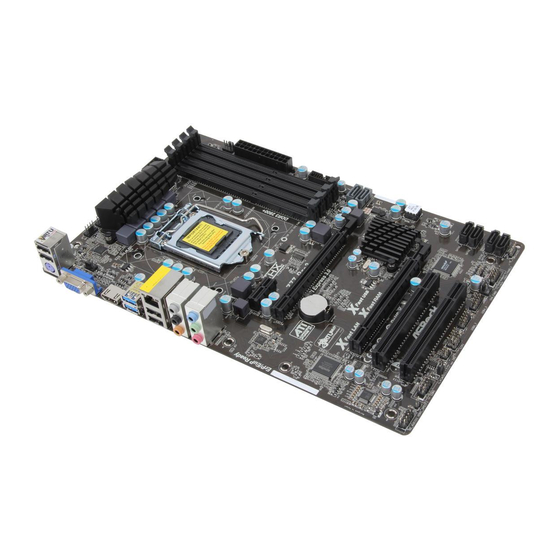
Page 13: Motherboard Layout
CPU_FAN1 ATX12V1 PWR_FAN1 CHA_FAN1 USB 3.0 T: USB2 B: USB3 USB 2.0 Top: T: USB2 RJ-45 B: USB3 PCIE1 SATA3_1 Z77 Pro3 SATA3_0 PCIE2 PCI Express 3.0 CMOS Battery Intel 64Mb BIOS Fast USB Fast LAN ast RAM PCIE3 RoHS... -
Page 14: I/O Panel
1.4 I/O Panel USB 2.0 Ports (USB01) Microphone (Pink) LAN RJ-45 Port USB 2.0 Ports (USB23) Side Speaker (Gray) USB 3.0 Ports (USB3_23) Rear Speaker (Black) HDMI Port (HDMI1) Central / Bass (Orange) D-Sub Port (VGA1) Line In (Light Blue) PS/2 Keyboard Port (Purple) ** 7 Front Speaker (Lime) - Page 15 To enable Multi-Streaming function, you need to connect a front panel audio cable to the front panel audio header. After restarting your computer, you will fi nd “Mixer” tool on your system. Please select “Mixer ToolBox” , click “Enable playback multi-streaming”, and click “ok”.
-
Page 16: Installation
Chapter 2: Installation This is an ATX form factor (12.0" x 7.6", 30.5 x 19.3 cm) motherboard. Before you install the motherboard, study the confi guration of your chassis to ensure that the motherboard fi ts into it. Make sure to unplug the power cord before installing or removing the motherboard. -
Page 17: Cpu Installation
2.3 CPU Installation For the installation of Intel 1155-Pin CPU, please follow the steps below. Load Plate Load Lever Socket Body Contact Array 1155-Pin Socket Overview Before you insert the 1155-Pin CPU into the socket, please check if the CPU surface is unclean or if there are any bent pins in the socket. Do not force to insert the CPU into the socket if above situation is found. - Page 18 Step 3. Insert the 1155-Pin CPU: Step 3-1. Hold the CPU by the edge which is marked with a black line. Step 3-2. Orient the CPU with the IHS (Inte- grated Heat Sink) up. Locate Pin1 and the two orientation key notches. orientation key notch alignment key Pin1...
-
Page 19: Installation Of Cpu Fan And Heatsink
2.4 Installation of CPU Fan and Heatsink This motherboard is equipped with 1155-Pin socket that supports Intel 1155-Pin CPUs. Please adopt the type of heatsink and cooling fan compliant with Intel 1155- Pin CPU to dissipate heat. Before you install the heatsink, you need to spray ther- mal interface material between the CPU and the heatsink to improve heat dissipa- tion. -
Page 20: Installation Of Memory Modules (Dimm)
2.5 Installation of Memory Modules (DIMM) This motherboard provides four 240-pin DDR3 (Double Data Rate 3) DIMM slots, and supports Dual Channel Memory Technology. For dual channel confi g- uration, you always need to install identical (the same brand, speed, size and chip-type) DDR3 DIMM pair in the slots: You have to install identical DDR3 DIMMs in Dual Channel A (DDR3_A1 and DDR3_B1;... -
Page 21: Installing A Dimm
Installing a DIMM Please make sure to disconnect power supply before adding or removing DIMMs or the system components. Step 1. Unlock a DIMM slot by pressing the retaining clips outward. Step 2. Align a DIMM on the slot such that the notch on the DIMM matches the break on the slot. -
Page 22: Expansion Slots (Pci And Pci Express Slots)
PCIE slots: PCIE1 (PCIE 2.0 x1 slot) is used for a PCI Express x1 lane width card, such as a Gigabit LAN card, SATA2 card or ASRock Game Blaster, etc. PCIE2 (PCIE 3.0 x16 slot) is used for PCI Express x16 lane width... -
Page 23: Crossfirex
2.7 CrossFireX and Quad CrossFireX Operation Guide This motherboard supports CrossFireX and Quad CrossFireX feature. CrossFireX technology offers the most advantageous means available of combining multiple high performance Graphics Processing Units (GPU) in a single PC. Combining a range of different operating modes with intelligent software design and an innovative interconnect mechanism, CrossFireX enables the highest possible level of performance and image quality in any 3D application. - Page 24 Step 2. Connect two Radeon graphics cards by installing CrossFire Bridge on CrossFire Bridge Interconnects on the top of Radeon graphics cards. (CrossFire Bridge is provided with the graphics card you purchase, not bundled with this motherboard. Please refer to your graphics card vendor for details.) CrossFire Bridge Step 3.
-
Page 25: Driver Installation And Setup
2.7.2 Driver Installation and Setup Step 1. Power on your computer and boot into OS. Step 2. Remove the ATI driver if you have any VGA driver installed in your system. The Catalyst Uninstaller is an optional download. We recommend using this utility to uninstall any previously installed Catalyst drivers prior to installation. - Page 26 Although you have selected the option “Enable CrossFire ”, the CrossFireX function may not work actually. Your computer will automatically reboot. After restarting your computer, please confi rm whether the option “Enable CrossFire ” in “AMD Catalyst Control Center” is selected or not; if not, please select it again, and then you are able to enjoy the benefi...
-
Page 27: Dual Monitor And Surround Display Features
2.8 Dual Monitor and Surround Display Features Dual Monitor Feature This motherboard supports dual monitor feature. With the internal VGA output sup- port (D-Sub and HDMI), you can easily enjoy the benefi ts of dual monitor feature without installing any add-on VGA cards to this motherboard. This motherboard also provides independent display controllers for D-Sub and HDMI to support dual VGA output so that D-sub and HDMI can drive same or different display contents. - Page 28 Surround Display Feature This motherboard supports surround display upgrade. With the internal VGA output support (D-Sub and HDMI) and external add-on PCI Express VGA cards, you can easily enjoy the benefi ts of surround display feature. Please refer to the following steps to set up a surround display environment: 1.
- Page 29 ® For Windows 7 / 7 64-bit / Vista / Vista 64-bit OS: Right click the desktop, choose “Personalize”, and select the “Display Settings” tab so that you can adjust the parameters of the multi-monitors according to the steps below. A.
-
Page 30: Asrock Smart Remote Installation Guide
The Multi-Angle CIR Receiver does not support Hot-Plug function. Please install it before you boot the system. * ASRock Smart Remote is only supported by some of ASRock motherboards. Please refer to ASRock website for the motherboard support list: http://www.asrock.com... -
Page 31: Jumpers Setup
2.10 Jumpers Setup The illustration shows how jumpers are setup. When the jumper cap is placed on pins, the jumper is “Short”. If no jumper cap is placed on pins, the jumper is “Open”. The illustration shows a 3-pin jumper whose pin1 and pin2 are “Short”... -
Page 32: Onboard Headers And Connectors
2.11 Onboard Headers and Connectors Onboard headers and connectors are NOT jumpers. Do NOT place jumper caps over these headers and connectors. Placing jumper caps over the headers and connectors will cause permanent damage of the motherboard! Serial ATA2 Connectors These four Serial ATA2 (SATA2) SATA2_2 connectors support SATA data... - Page 33 (9-pin USB8_9) USB_PWR (see p.13, No. 24) DUMMY USB_PWR USB 3.0 Header Besides two default USB 3.0 Vbus Vbus ports on the I/O panel, there is (19-pin USB3_0_1) Vbus IntA_P1_SSRX- IntA_P0_SSRX- IntA_P1_SSRX+ one USB 3.0 header on this (see p.13, No. 9) IntA_P0_SSRX+ IntA_P1_SSTX- motherboard.
- Page 34 E. To activate the front mic. ® For Windows XP / XP 64-bit OS: Select “Mixer”. Select “Recorder”. Then click “FrontMic”. ® For Windows 7 / 7 64-bit / Vista / Vista 64-bit OS: Go to the “FrontMic” Tab in the Realtek Control panel. Adjust “Recording Volume”.
- Page 35 Power LED Header Please connect the chassis power LED to this header to (3-pin PLED1) PLED- PLED+ PLED+ indicate system power status. (see p.13, No. 19) The LED is on when the system is operating. The LED keeps blinking in S1/S3 state. The LED is off in S4 state or S5 state (power off).
- Page 36 Though this motherboard provides 24-pin ATX power connector, it can still work if you adopt a traditional 20-pin ATX power supply. To use the 20-pin ATX power supply, please plug your power supply along with Pin 1 and Pin 13. 20-Pin ATX Power Supply Installation ATX 12V Power Connector Please connect an ATX 12V...
-
Page 37: Serial Ata (Sata) / Serial Ata2 (Sata2) Hard Disks Installation
2.12 Serial ATA (SATA) / Serial ATA2 (SATA2) Hard Disks Installation ® This motherboard adopts Intel Z77 chipset that supports Serial ATA (SATA) / Serial ATA2 (SATA2) hard disks and RAID (RAID 0, RAID 1, RAID 5, RAID 10, Intel Rapid Storage and Intel Smart Response Technology) functions. -
Page 38: Hot Plug And Hot Swap Functions For Sata / Sata2 Hdds
2.14 Hot Plug and Hot Swap Functions for SATA / SATA2 HDDs This motherboard supports Hot Plug and Hot Swap functions for SATA / SATA2 in ® RAID / AHCI mode. Intel Z77 chipset provides hardware support for Advanced Host controller Interface (AHCI), a new programming interface for SATA host controllers developed through a joint industry effort. -
Page 39: Sata / Sata2 / Sata3 Hdd Hot Plug Feature And Operation Guide
SATA / SATA2 / SATA3 Hot Plug support information of our motherboard is indicated in the product spec on our website: www.asrock.com 2. Make sure your SATA / SATA2 / SATA3 HDD can support Hot Plug function from your dealer or HDD user manual. - Page 40 How to Hot Plug a SATA / SATA2 / SATA3 HDD: Points of attention, before you process the Hot Plug: Please do follow below instruction sequence to process the Hot Plug, improper procedure will cause the SATA / SATA2 / SATA3 HDD damage and data loss. Step 1 Step 2 Please connect SATA power cable 1x4-...
-
Page 41: Driver Installation Guide
2.17 Driver Installation Guide To install the drivers to your system, please insert the support CD to your optical drive fi rst. Then, the drivers compatible to your system can be auto-detected and listed on the support CD driver page. Please follow the order from top to bottom to install those required drivers. -
Page 42: Xp / Xp 64-Bit Without Raid Functions
2.19 Installing Windows 7 / 7 64-bit / Vista / Vista 64-bit / XP / ® XP 64-bit Without RAID Functions ® If you want to install Windows 7 / 7 64-bit / Vista / Vista 64-bit / XP / XP 64-bit OS on your SATA / SATA2 / SATA3 HDDs without RAID functions, please follow the procedures below according to the OS you install. -
Page 43: Uefi Setup Utility
Chapter 3: UEFI SETUP UTILITY 3.1 Introduction This section explains how to use the UEFI SETUP UTILITY to confi gure your system. The UEFI chip on the motherboard stores the UEFI SETUP UTILITY. You may run the UEFI SETUP UTILITY when you start up the computer. Please press <F2>... -
Page 44: Navigation Keys
3.1.2 Navigation Keys Please check the following table for the function description of each navigation key. Navigation Key(s) Function Description Moves cursor left or right to select Screens Moves cursor up or down to select items + / - To change option for the selected items <Tab>... -
Page 45: Oc Tweaker Screen
3.3 OC Tweaker Screen In the OC Tweaker screen, you can set up overclocking features. Advanced Turbo 30 You can use this option to increase your system performance. This option appears only when your CPU supports this function. Load Optimized CPU OC Setting You can use this option to load optimized CPU overclocking setting. - Page 46 Please note that enabling this function may reduce CPU voltage and lead to system stability or compatibility issues with some power supplies. Please set this item to [Disabled] if above issues occur. Intel Turbo Boost Technology Use this item to enable or disable Intel Turbo Boost Mode Technology. Turbo Boost Mode allows processor cores to run faster than marked fre- quency in specifi...
- Page 47 DRAM Timing Control DRAM tCL Use this item to change CAS# Latency (tCL) Auto/Manual setting. The default is [Auto]. DRAM tRCD Use this item to change RAS# to CAS# Delay (tRCD) Auto/Manual setting. The default is [Auto]. DRAM tRP Use this item to change Row Precharge Time (tRP) Auto/Manual setting. The default is [Auto].
- Page 48 DRAM tRTP Use this item to change Read to Precharge (tRTP) Auto/Manual setting. The default is [Auto]. DRAM tFAW Use this item to change Four Activate Window (tFAW) Auto/Manual set- ting. The default is [Auto]. DRAM tCWL Use this item to change CAS# Write Latency (tCWL) Auto/Manual setting. The default is [Auto].
- Page 49 CPU PLL Voltage Use this to select CPU PLL Voltage. The default value is [Auto]. VCCSA Voltage Use this to select VCCSA Voltage. The default value is [Auto]. User Defaults In this option, you are allowed to load and save three user defaults according to your own requirements.
-
Page 50: Advanced Screen
3.4 Advanced Screen In this section, you may set the confi gurations for the following items: CPU Confi gu- ration, North Bridge Confi guration, South Bridge Confi guration, Storage Confi gura- tion, Intel(R) Rapid Start Technology, Intel(R) Smart Connect Technology, Super IO Confi... -
Page 51: Cpu Confi Guration
3.4.1 CPU Configuration Intel Hyper Threading Technology To enable this feature, a computer system with an Intel processor that sup- ports Hyper-Threading technology and an operating system that includes ® ® optimization for this technology, such as Microsoft Windows XP / Vista ®... - Page 52 No-Execute Memory Protection No-Execution (NX) Memory Protection Technology is an enhancement to the IA-32 Intel Architecture. An IA-32 processor with “No Execute (NX) Memory Protection” can prevent data pages from being used by malicious software to execute codes. This option will be hidden if the current CPU does not support No-Excute Memory Protection.
-
Page 53: North Bridge Confi Guration
3.4.2 North Bridge Configuration Primary Graphics Adapter This allows you to select [Onboard], [PCI] or [PCI Express] as the boot graphic adapter priority. The default value is [PCI Express]. VT-d ® ® Use this to enable or disable Intel VT-d technology (Intel Virtualization Technology for Directed I/O). -
Page 54: South Bridge Confi Guration
3.4.3 South Bridge Configuration Onboard HD Audio Select [Auto], [Enabled] or [Disabled] for the onboard HD Audio feature. If you select [Auto], the onboard HD Audio will be disabled when PCI Sound Card is plugged. Front Panel Select [Auto] or [Disabled] for the onboard HD Audio Front Panel. On/Off Play Use this item to enable or disable On/Off Play Technology. -
Page 55: Storage Confi Guration
3.4.4 Storage Configuration SATA Controller(s) Use this item to enable or disable the SATA Controller feature. SATA Mode Selection Use this to select SATA mode. Confi guration options: [IDE Mode], [AHCI Mode] and [RAID Mode]. The default value is [AHCI Mode]. AHCI (Advanced Host Controller Interface) supports NCQ and other new features that will improve SATA disk performance but IDE mode does not have these advantages. -
Page 56: Intel(R) Rapid Start Technology
3.4.5 Intel(R) Rapid Start Technology Intel(R) Rapid Start Technology Use this item to enable or disable Intel(R) Rapid Start Technology. Intel(R) Rapid Start Technology is a new zero power hibernation mode which al- lows users to resume in just 5-6 seconds. The default is [Disabled]. -
Page 57: Intel(R) Smart Connect Technology
3.4.6 Intel(R) Smart Connect Technology Intel(R) Smart Connect Technology Use this item to enable or disable Intel(R) Smart Connect Technology. Intel(R) Smart Connect Technology keeps your e-mail and social networks, such as Twitter, Facebook, etc. updated automatically while the computer is in sleep mode. -
Page 58: Super Io Confi Guration
3.4.7 Super IO Configuration Serial Port Use this item to enable or disable the onboard serial port. Serial Port Address Use this item to set the address for the onboard serial port. Confi guration options: [3F8h / IRQ4] and [3E8h / IRQ4]. Infrared Port Use this item to enable or disable the onboard infrared port. -
Page 59: Acpi Confi Guration
3.4.8 ACPI Configuration Suspend to RAM Use this item to select whether to auto-detect or disable the Suspend-to- RAM feature. Selecting [Auto] will enable this feature if the OS supports it. Check Ready Bit Use this item to enable or disable the feature Check Ready Bit. ACPI HPET Table Use this item to enable or disable ACPI HPET Table. -
Page 60: Usb Confi Guration
OMG (Online Management Guard) Administrators are able to establish an internet curfew or restrict internet access at specifi ed times via OMG. You may choose from [Everyday], [Day of the week] or [Weekdays and weekends], then schedule the starting and ending hours of internet access granted to other users. -
Page 61: Hardware Health Event Monitoring Screen
3.5 Hardware Health Event Monitoring Screen In this section, it allows you to monitor the status of the hardware on your system, including the parameters of the CPU temperature, motherboard temperature, CPU fan speed, chassis fan speed, and the critical voltage. CPU Fan 1 &... -
Page 62: Boot Screen
3.6 Boot Screen In this section, it will display the available devices on your system for you to confi g- ure the boot settings and the boot priority. Setup Prompt Timeout This shows the number of seconds to wait for setup activation key. 65535(0XFFFF) means indefi... -
Page 63: Security Screen
3.7 Security Screen In this section, you may set or change the supervisor/user password for the system. For the user password, you may also clear it. -
Page 64: Exit Screen
3.8 Exit Screen Save Changes and Exit When you select this option, the following message “Save confi guration changes and exit setup?” will pop-out. Select [Yes] to save the changes and exit the UEFI SETUP UTILITY. Discard Changes and Exit When you select this option, the following message “Discard changes and exit setup?”... -
Page 65: Software Support
Click on a specifi c item then follow the installation wizard to install it. 4.2.4 Contact Information If you need to contact ASRock or want to know more about ASRock, welcome to visit ASRock’s website at http://www.asrock.com; or you may contact your... - Page 66 Installing OS on a HDD Larger Than 2TB in AHCI Mode ® This motherboard adopts UEFI BIOS that allows Windows OS to be installed on a large size HDD (>2TB). Please follow the procedures below to install the operating system. ®...
-
Page 67: Installing Os On A Hdd Larger Than 2Tb In Raid Mode
RAID drivers into a USB fl ash disk. You can download the driver from ASRock's website and unzip the fi le into a USB fl ash disk OR copy the fi le from ASRock motherboard support CD. (please copy the fi les under following directory: 32 bit: ..\i386\Win7_Vista_Intel_v11.0.0.1032... - Page 68 E. Please keep the USB fl ash disk installed until the system's fi rst reboot. ® F. Continue to install OS by following the Windows instructions. ® 5. Follow Windows Installation Guide to install OS. ® If you install Windows 7 64-bit / Vista 64-bit on a large hard disk (ex.
- Page 69 B. Disable “Volume Shadow Copy” service. a. Type “computer management” in the Start Menu, then press “Enter”. b. Go to “Services and Applications>Services”; Then double click “Volume Shadow Copy”.
- Page 70 c. Set “Startup type” to “Disable” then Click “OK”. C. Reboot your system. D. After reboot, please start to install motherboard drivers and utilities. ® Windows 7 64-bit: A. Please request the hotfi x KB2505454 through this link: http://support.microsoft.com/kb/2505454/ ® B.
Need help?
Do you have a question about the Z77 Pro3 and is the answer not in the manual?
Questions and answers