
Related Manuals for ASROCK H61M-ITX


Summary of Contents for ASROCK H61M-ITX
-
Page 1: User Manual
H61M-ITX User Manual Version 1.0 Published May 2011 Copyright©2011 ASRock INC. All rights reserved. -
Page 2: Copyright Notice
fi tness for a particular purpose. In no event shall ASRock, its directors, offi cers, employees, or agents be liable for any indirect, special, incidental, or consequential damages (including damages for loss of profi... -
Page 3: Table Of Contents
2.5 Installation of Memory Modules (DIMM) ......18 2.6 Expansion Slot (PCI Express Slot) ........19 2.7 Dual Monitor and Surround Display Features ....20 2.8 ASRock Smart Remote Installation Guide ..... 23 2.9 Jumpers Setup ............24 2.10 Onboard Headers and Connectors ......24 2.11 Serial ATA (SATA) / Serial ATAII (SATAII) Hard Disks... - Page 4 3 UEFI SETUP UTILITY ..........33 3.1 Introduction ..............33 3.1.1 UEFI Menu Bar ............ 33 3.1.2 Navigation Keys ........... 34 3.2 Main Screen ..............34 3.3 OC Tweaker Screen ............35 3.4 Advanced Screen ............38 3.4.1 CPU Confi guration ..........39 3.4.2 North Bridge Confi...
-
Page 5: Introduction
In case any modifi cations of this manual occur, the updated version will be available on ASRock website without further notice. You may fi nd the latest VGA cards and CPU support lists on ASRock website as well. -
Page 6: Specifi Cations
Specifications Platform - Mini-ITX Form Factor: 6.7-in x 6.7-in, 17.0 cm x 17.0 cm - All Solid Capacitor design (100% Japan-made high-quality Conductive Polymer Capacitors) ® - Supports 2nd Generation Intel Core i7 / i5 / i3 in LGA1155 Package ®... - Page 7 CyberLink MediaEspresso 6.5 Trial, ASRock Software Suite (CyberLink DVD Suite - OEM and Trial) Unique Feature - ASRock Extreme Tuning Utility (AXTU) (see CAUTION 8) - ASRock Instant Boot - ASRock Instant Flash (see CAUTION 9) - ASRock APP Charger (see CAUTION 10)
- Page 8 - FCC, CE, WHQL - ErP/EuP Ready (ErP/EuP ready power supply is required) (see CAUTION 15) * For detailed product information, please visit our website: http://www.asrock.com WARNING Please realize that there is a certain risk involved with overclocking, including adjusting the setting in the BIOS, applying Untied Overclocking Technology, or using the third-party overclocking tools.
- Page 9 6-channel, and 8-channel modes. Please check the table on page 13 for proper connection. ASRock Extreme Tuning Utility (AXTU) is an all-in-one tool to fi ne-tune different system functions in a user-friendly interface, which is including Hardware Monitor, Fan Control, Overclocking, OC DNA and IES. In Hardware Monitor, it shows the major readings of your system.
- Page 10 ASRock Instant Flash is a BIOS fl ash utility embedded in Flash ROM. This convenient BIOS update tool allows you to update system BIOS ® without entering operating systems fi rst like MS-DOS or Windows . With this utility, you can press <F6> key during the POST or press <F2> key to BIOS setup menu to access ASRock Instant Flash.
- Page 11 15. EuP, stands for Energy Using Product, was a provision regulated by Eu- ropean Union to defi ne the power consumption for the completed system. According to EuP, the total AC power of the completed system shall be under 1.00W in off mode condition. To meet EuP standard, an EuP ready motherboard and an EuP ready power supply are required.
-
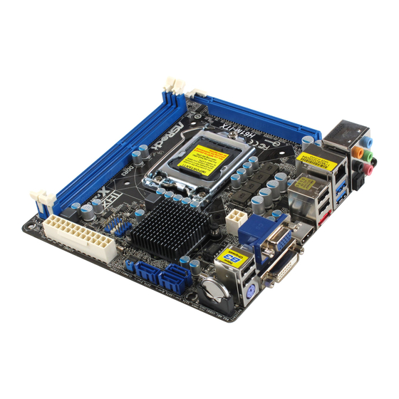
Page 12: Motherboard Layout
ATX12V1 USB 2.0 T: USB2 B: USB3 USB 3.0 Top: T: USB4 RJ-45 B: USB5 HD_AUDIO1 H61M-ITX AUDIO CODEC PCIE1 HDMI 1.4a USB 3.0 RoHS Designed in Taipei System Panel Header (PANEL1, White) 1155-Pin CPU Socket SATA2 Connector (SATA_1 (PORT 1), Blue) PCI Express 2.0 x16 Slot (PCIE1, Blue) -
Page 13: I/O Panel
1.4 I/O Panel USB 2.0 Ports (USB01) ** 9 Front Speaker (Lime) D-Sub Port Microphone (Pink) USB 2.0 Ports (USB23) USB 3.0 Ports (USB45) LAN RJ-45 Port eSATA2 Port Central / Bass (Orange) HDMI Port Rear Speaker (Black) DVI-D Port Optical SPDIF Out Port PS/2 Keyboard Port (Purple) Line In (Light Blue) -
Page 14: Installation
Chapter 2: Installation This is a Mini-ITX form factor (6.7" x 6.7", 17.0 x 17.0 cm) motherboard. Before you install the motherboard, study the confi guration of your chassis to ensure that the motherboard fi ts into it. Make sure to unplug the power cord before installing or removing the motherboard. -
Page 15: Cpu Installation
2.3 CPU Installation For the installation of Intel 1155-Pin CPU, please follow the steps below. Load Plate Load Lever Socket Body Contact Array 1155-Pin Socket Overview Before you insert the 1155-Pin CPU into the socket, please check if the CPU surface is unclean or if there is any bent pin on the socket. Do not force to insert the CPU into the socket if above situation is found. - Page 16 Step 3. Insert the 1155-Pin CPU: Step 3-1. Hold the CPU by the edge where is marked with black line. Step 3-2. Orient the CPU with IHS (Integrated Heat Sink) up. Locate Pin1 and the two orientation key notches. orientation key notch alignment key Pin1 Pin1...
-
Page 17: Installation Of Cpu Fan And Heatsink
Installation of CPU Fan and Heatsink This motherboard is equipped with 1155-Pin socket that supports Intel 1155-Pin CPU. Please adopt the type of heatsink and cooling fan compliant with Intel 1155- Pin CPU to dissipate heat. Before you installed the heatsink, you need to spray thermal interface material between the CPU and the heatsink to improve heat dis- sipation. -
Page 18: Installation Of Memory Modules (Dimm)
2.5 Installation of Memory Modules (DIMM) This motherboard provides two 240-pin DDR3 (Double Data Rate 3) DIMM slots, and supports Dual Channel Memory Technology. For dual channel configuration, you always need to install two identical (the same brand, speed, size and chip- type) memory modules in the DDR3 DIMM slots to activate Dual Channel Memory Technology. -
Page 19: Expansion Slot (Pci Express Slot)
2.6 Expansion Slot (PCI Express Slot) There is 1 PCI Express slot on this motherboard. PCIE slots: PCIE1 (PCIE x16 slot; Blue) is used for PCI Express x16 lane width graphics cards. Installing an expansion card Step 1. Before installing the expansion card, please make sure that the power supply is switched off or the power cord is unplugged. -
Page 20: Dual Monitor And Surround Display Features
2.7 Dual Monitor and Surround Display Features Dual Monitor Feature This motherboard supports dual monitor feature. With the internal VGA output sup- port (DVI-D, D-Sub and HDMI), you can easily enjoy the benefi ts of dual monitor feature without installing any add-on VGA card to this motherboard. This mother- board also provides independent display controllers for DVI-D, D-Sub and HDMI to support dual VGA output so that DVI-D, D-sub and HDMI can drive same or different display contents. - Page 21 Surround Display Feature This motherboard supports surround display upgrade. With the internal VGA output support (DVI-D, D-Sub and HDMI) and external add-on PCI Express VGA cards, you can easily enjoy the benefi ts of surround display feature. Please refer to the following steps to set up a surround display environment: 1.
- Page 22 ® For Windows 7 / 7 64-bit / Vista / Vista 64-bit OS: Right click the desktop, choose “Personalize”, and select the “Display Settings” tab so that you can adjust the parameters of the multi-monitor according to the steps below. A.
-
Page 23: Asrock Smart Remote Installation Guide
The Multi-Angle CIR Receiver does not support Hot-Plug function. Please install it before you boot the system. * ASRock Smart Remote is only supported by some of ASRock motherboards. Please refer to ASRock website for the motherboard support list: http://www.asrock.com... -
Page 24: Jumpers Setup
2.9 Jumpers Setup The illustration shows how jumpers are setup. When the jumper cap is placed on pins, the jumper is “Short”. If no jumper cap is placed on pins, the jumper is “Open”. The illustration shows a 3-pin jumper whose pin1 and pin2 are “Short”... - Page 25 Serial ATA (SATA) Either end of the SATA data Data Cable cable can be connected to the SATA / SATAII hard disk or the (Optional) SATAII connector on this motherboard. 3.5mm Audio Cable Either end of the 3.5mm audio cable can be connected to the (Optional) portable audio devices, such as MP3 player and mobile...
-
Page 26: Front Panel Audio Header
1. High Defi nition Audio supports Jack Sensing, but the panel wire on the chassis must support HDA to function correctly. Please follow the instruction in our manual and chassis manual to install your system. 2. If you use AC’97 audio panel, please install it to the front panel audio header as below: A. - Page 27 Power LED Header Please connect the chassis power LED to this header to (3-pin PLED1) PLED- PLED+ PLED+ indicate system power status. (see p.12 No. 19) The LED is on when the system is operating. The LED keeps blinking in S1 state. The LED is off in S3/S4 state or S5 state (power off).
-
Page 28: Serial Ata (Sata) / Serial Ataii (Sataii) Hard Disks Installation
2.11 Serial ATA (SATA) / Serial ATAII (SATAII) Hard Disks Installation ® This motherboard adopts Intel H61 chipset that supports Serial ATA (SATA) / Serial ATAII (SATAII) hard disks. You may install SATA / SATAII hard disks on this mother- board for internal storage devices. -
Page 29: Sata / Sataii Hdd Hot Plug Feature And Operation Guide
3. Please make sure the SATA / SATAII driver is installed into system properly. The latest SATA / SATAII driver is available on our support website: www.asrock.com 4. Make sure to use the SATA power cable & data cable, which are from our motherboard package. -
Page 30: How To Hot Plug A Sata / Sataii Hdd
How to Hot Plug a SATA / SATAII HDD: Points of attention, before you process the Hot Plug: Please do follow below instruction sequence to process the Hot Plug, improper procedure will cause the SATA / SATAII HDD damage and data loss. Step 1 Step 2 Please connect SATA power cable 1x4-pin end... -
Page 31: Driver Installation Guide
2.14 Driver Installation Guide To install the drivers to your system, please insert the support CD to your optical drive fi rst. Then, the drivers compatible to your system can be auto-detected and listed on the support CD driver page. Please follow the order from up to bottom side to install those required drivers. -
Page 32: 64-Bit / Vista
® STEP 3: Install Windows XP / XP 64-bit OS on your system. ® After making a SATA / SATAII driver diskette, you can start to install Windows ® / XP 64-bit on your system. At the beginning of Windows setup, press F6 to install a third-party AHCI driver. -
Page 33: Uefi Setup Utility
Chapter 3: UEFI SETUP UTILITY Introduction This section explains how to use the UEFI SETUP UTILITY to confi gure your system. The UEFI chip on the motherboard stores the UEFI SETUP UTILITY. You may run the UEFI SETUP UTILITY when you start up the computer. Please press <F2>... -
Page 34: Navigation Keys
3.1.2 Navigation Keys Please check the following table for the function description of each navigation key. Navigation Key(s) Function Description Moves cursor left or right to select Screens Moves cursor up or down to select items + / - To change option for the selected items <Enter>... -
Page 35: Oc Tweaker Screen
3.3 OC Tweaker Screen In the OC Tweaker screen, you can set up overclocking features. CPU Control CPU Ratio Setting Use this item to change the ratio value of this motherboard. GT Over Clock Use this to enable or disable GT Over Clock by Internal Graphics Device. - Page 36 DRAM Timing Control DRAM Frequency If [Auto] is selected, the motherboard will detect the memory module(s) in- serted and assigns appropriate frequency automatically for better compati- bility. If you want the max performance for DDR3 1333 memory module(s), please manually adjust it to 1333. CAS# Latency (tCL) Use this item to change CAS# Latency (tCL) Auto/Manual setting.
- Page 37 Four Activate Window (tFAW) Use this item to change Four Activate Window (tFAW) Auto/Manual set- ting. The default is [Auto]. Memory Power Down Mode Use this item to adjust DDR power down mode. Configuration options: [Auto], [Slow] and [Fast]. The default value is [Auto]. Voltage Control DRAM Voltage Use this to select DRAM Voltage.
-
Page 38: Advanced Screen
3.4 Advanced Screen In this section, you may set the confi gurations for the following items: CPU Confi gu- ration, North Bridge Confi guration, South Bridge Confi guration, Storage Confi gura- tion, Super IO Confi guration, ACPI Confi guration and USB Confi guration. Setting wrong values in this section may cause the system to malfunction. -
Page 39: Cpu Confi Guration
3.4.1 CPU Configuration Intel Hyper Threading Technology To enable this feature, it requires a computer system with an Intel processor that supports Hyper-Threading technology and an operating ® system that includes optimization for this technology, such as Microsoft ® ® ®... - Page 40 CPU Thermal Throttling You may select [Enabled] to enable CPU internal thermal control mechanism to keep the CPU from overheated. Intel Virtualization Technology When this option is set to [Enabled], a VMM (Virtual Machine Architecture) can utilize the additional hardware capabilities provided by Vanderpool Technology.
-
Page 41: North Bridge Confi Guration
3.4.2 North Bridge Configuration Low MMIO Align Low MMIO resources align at 64MB/1024MB. The default value is [64MB]. VT-d ® ® Use this to enable or disable Intel VT-d technology (Intel Virtualization Technology for Directed I/O). The default value of this feature is [Disabled]. Primary Graphics Adapter This allows you to select the boot graphic adapter priority. - Page 42 DVMT Memory You are allowed to adjust the shared memory size in this item. Configuration options: [128MB], [256MB] and [Maximum]. The option [Maximum] only appears when you adopt the memory module with 1024MB or above.
-
Page 43: South Bridge Confi Guration
3.4.3 South Bridge Configuration Restore on AC/Power Loss This allows you to set the power state after an unexpected AC/power loss. If [Power Off] is selected, the AC/power remains off when the power recovers. If [Power On] is selected, the AC/power resumes and the system starts to boot up when the power recovers. -
Page 44: Storage Confi Guration
Good Night LED Enable this option to turn off Power LED and Port80 LED when the system is power on. The keyboard LED will also be turned off in S1, S3 and S4 state. The default value is [Auto]. 3.4.4 Storage Configuration SATA Mode Use this to select SATA mode. -
Page 45: Super Io Confi Guration
Hard Disk S.M.A.R.T. Use this item to enable or disable the S.M.A.R.T. (Self-Monitoring, Analy- sis, and Reporting Technology) feature. Confi guration options: [Disabled] and [Enabled]. 3.4.5 Super IO Configuration CIR Controller Use this item to enable or disable CIR controller. -
Page 46: Acpi Confi Guration
3.4.6 ACPI Configuration Suspend to RAM Use this item to select whether to auto-detect or disable the Suspend-to- RAM feature. Select [Auto] will enable this feature if the OS supports it. Check Ready Bit Use this item to enable or disable the feature Check Ready Bit. PS/2 Keyboard Power On Use this item to enable or disable PS/2 keyboard to turn on the system from the power-soft-off mode. -
Page 47: Usb Confi Guration
3.4.7 USB Configuration USB 2.0 Controller Use this item to enable or disable the use of USB 2.0 controller. USB 3.0 Controller Use this item to enable or disable the use of USB 3.0 controller. Legacy USB Support Use this option to select legacy support for USB devices. There are four confi... -
Page 48: Hardware Health Event Monitoring Screen
3.5 Hardware Health Event Monitoring Screen In this section, it allows you to monitor the status of the hardware on your system, including the parameters of the CPU temperature, motherboard temperature, CPU fan speed, chassis fan speed, and the critical voltage. CPU Fan Setting This allows you to set the CPU fan speed. -
Page 49: Boot Screen
3.6 Boot Screen In this section, it will display the available devices on your system for you to confi g- ure the boot settings and the boot priority. Setup Prompt Timeout This shows the number of seconds to wait for setup activation key. 65535(0XFFFF) means indefi... -
Page 50: Security Screen
3.7 Security Screen In this section, you may set or change the supervisor/user password for the system. For the user password, you may also clear it. -
Page 51: Exit Screen
3.8 Exit Screen Save Changes and Exit When you select this option, it will pop-out the following message, “Save confi guration changes and exit setup?” Select [OK] to save the changes and exit the UEFI SETUP UTILITY. Discard Changes and Exit When you select this option, it will pop-out the following message, “Discard changes and exit setup?”... -
Page 52: Software Support
Click on a specifi c item then follow the installation wizard to install it. 4.2.4 Contact Information If you need to contact ASRock or want to know more about ASRock, welcome to visit ASRock’s website at http://www.asrock.com; or you may contact your dealer for further information. - Page 53 Installing OS on a HDD Larger Than 2TB ® This motherboard is adopting UEFI BIOS that allows Windows OS to be installed on a large size HDD (>2TB). Please follow below procedure to install the operating system. ® 1. Please make sure to use Windows Vista 64-bit (with SP1 or above) or ®...
Need help?
Do you have a question about the H61M-ITX and is the answer not in the manual?
Questions and answers