Table of Contents
Advertisement
Advertisement
Table of Contents

Related Manuals for Asus P5G-MX


Summary of Contents for Asus P5G-MX
- Page 1 P5G-MX...
- Page 2 Product warranty or service will not be extended if: (1) the product is repaired, modified or altered, unless such repair, modification of alteration is authorized in writing by ASUS; or (2) the serial number of the product is defaced or missing.
-
Page 3: Table Of Contents
Contents Notices ......................vi Safety information ..................vii About this guide ..................viii Typography ....................ix P5G-MX specifications summary ............... x Chapter 1: Product introduction Welcome! ..................1-2 Package contents ................. 1-2 Special features ................1-2 1.3.1 Product highlights ............1-2 1.3.2... - Page 4 Creating a bootable floppy disk ........2-2 2.1.2 ASUS EZ Flash utility ............2-3 2.1.3 AFUDOS utility ..............2-4 2.1.4 ASUS CrashFree BIOS 2 utility ........2-6 2.1.5 ASUS Update utility ............2-7 BIOS setup program ..............2-10 2.2.1 BIOS menu screen ............2-11 2.2.2...
- Page 5 Support CD information .............. 3-2 3.2.1 Running the support CD ..........3-2 3.2.2 Drivers menu ..............3-3 3.2.3 Utilities menu ..............3-4 3.2.4 ASUS Contact information ..........3-5 Appendix: CPU features Enhanced Intel SpeedStep Technology (EIST) ......A-2 ® A.1.1 System requirements ............A-2 A.1.2 Using the EIST ..............A-2...
-
Page 6: Notices
Notices Federal Communications Commission Statement This device complies with Part 15 of the FCC Rules. Operation is subject to the following two conditions: • This device may not cause harmful interference, and • This device must accept any interference received including interference that may cause undesired operation. -
Page 7: Safety Information
Safety information Electrical safety • To prevent electrical shock hazard, disconnect the power cable from the electrical outlet before relocating the system. • When adding or removing devices to or from the system, ensure that the power cables for the devices are unplugged before the signal cables are connected. -
Page 8: About This Guide
Refer to the following sources for additional information and for product and software updates. ASUS websites The ASUS website provides updated information on ASUS hardware and software products. Refer to the ASUS contact information. Optional documentation Your product package may include optional documentation, such as warranty flyers, that may have been added by your dealer. -
Page 9: Typography
Conventions used in this guide To make sure that you perform certain tasks properly, take note of the following symbols used throughout this manual. DANGER/WARNING: Information to prevent injury to yourself when trying to complete a task. CAUTION: Information to prevent damage to the components when trying to complete a task. -
Page 10: P5G-Mx Specifications Summary
06/05B/05A processors ® Supports Intel Enhanced Intel SpeedStep Technology (EIST), ® ® and Intel Hyper-Threading Technology ® * Refer to www.asus.com for Intel CPU support list Chipset Northbridge: Intel 945GC ® Southbridge: Intel ICH7 ® Front Side Bus 1066/800 MHz... - Page 11 P5G-MX specifications summary Special features ASUS EZ Flash ASUS CrashFree BIOS 2 ASUS MyLogo™ ASUS Q-Fan Manageability WOL, PXE, WOR by Ring, PME Wake UP Support OS Windows XP / Vista ® Internal connectors 2 x USB 2.0 connectors for 4 additional USB 2.0 ports...
-
Page 13: Chapter 1: Product Introduction
This chapter describes the motherboard features and the new technologies it supports. Product introduction... -
Page 14: Welcome
Green ASUS This motherboard and its packaging comply with the European Union’s Restriction on the use of Hazardous Substances (RoHS). This is in line with the ASUS vision of creating environment-friendly and recyclable products/packaging to safeguard consumers’ health while minimizing the impact on the environment. - Page 15 PCI bus. PCI Express features point-to-point serial interconnections between devices and allows higher clockspeeds by carrying data in packets. This high speed interface is software compatible with existing PCI specifications. See page 1-22 for details. ASUS P5G-MX...
-
Page 16: Innovative Asus Features
ROM chip. See page 2-6 for details. ASUS EZ Flash With the ASUS EZ Flash, you can easily update the system BIOS even before loading the operating system. No need to use a DOS-based utility or boot from a floppy disk. -
Page 17: Before You Proceed
ON, in sleep mode, or in soft-off mode. This is a reminder that you should shut down the system and unplug the power cable before removing or plugging in any motherboard component. The illustration below shows the location of the onboard LED. SB_PWR Standby Powered Power P5G-MX Onboard LED ASUS P5G-MX... -
Page 18: Motherboard Overview
Motherboard overview Before you install the motherboard, study the configuration of your chassis to ensure that the motherboard fits into it. Make sure to unplug the power cord before installing or removing the motherboard. Failure to do so can cause you physical injury and damage motherboard components. -
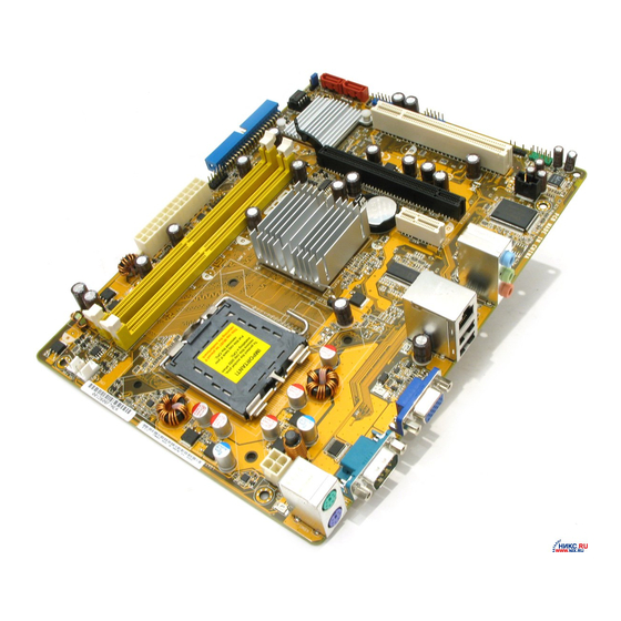
Page 19: Motherboard Layout
PS/2KBMS T: Mouse B: Keyboard ATX12V LGA775 LAN1_USB12 Intel 82945GC ICS 9L PRS412 AUDIO CR2032 3V PCIEX1_1 Lithium Cell CMOS Power Attansic PCIEX16 Super I/O Intel ICH7 BIOS PCI1 ALC662 PS2_USBPWR AAFP USB34 USB56 SATA1 SATA2 SPDIF_OUT SB_PWR ASUS P5G-MX... -
Page 20: Central Processing Unit (Cpu)
Contact your retailer immediately if the PnP cap is missing, or if you see any damage to the PnP cap/socket pins/motherboard components. ASUS will shoulder the cost of repair only if the damage is shipment/transit-related. - Page 21 (B). Load plate Position the CPU over the socket, making sure that the gold triangle is on the bottom-left corner of the socket. The socket alignment key should fit into Alignment key the CPU notch. Gold triangle mark ASUS P5G-MX...
- Page 22 Close the load plate (A), then push the load lever (B) until it snaps into the retention tab. The CPU fits in only one correct orientation. DO NOT force the CPU into the socket to prevent bending the connectors on the socket and damaging the CPU! The motherboard supports Intel LGA775 processors with the Intel Enhanced...
-
Page 23: Installling The Cpu Heatsink And Fan
Place the heatsink on top of the installed CPU, making sure that the four fasteners match the holes on the motherboard. Fastener Motherboard hole Make sure each fastener is oriented as shown, with the narrow groove directed outward. ASUS P5G-MX 1-11... - Page 24 CPU_FAN. CPU_FAN +12V CPU FAN IN CPU FAN PWM P5G-MX CPU Fan Connector • Do not forget to connect the CPU fan connector! Hardware monitoring errors can occur if you fail to plug this connector. •...
-
Page 25: Uninstalling The Cpu Heatsink And Fan
To uninstall the CPU heatsink and fan: Disconnect the CPU fan cable from the connector on the motherboard. Rotate each fastener counterclockwise. Pull up two fasteners at a time in a diagonal sequence to disengage the heatsink and fan assembly from the motherboard. ASUS P5G-MX 1-13... - Page 26 Remove the heatsink and fan assembly from the motherboard. Rotate each fastener clockwise to reset the orientation. Narrow end of the groove The narrow end of the groove should point outward after resetting. (The photo shows the groove shaded for emphasis.) 1-14 Chapter 1: Product introduction...
-
Page 27: System Memory
240-pin footprint compared to the 184-pin DDR DIMM. DDR2 DIMMs are notched differently to prevent installation on a DDR DIMM socket. The figure illustrates the location of the DDR2 DIMM sockets: P5G-MX 240-pin DDR2 DIMM Sockets Channel Sockets Channel A... -
Page 28: Ddr2 Qualified Vendors List
DDR2 Qualified Vendors List The following table lists the memory modules that have been tested and qualified for use with this motherboard. Visit the ASUS website (www.asus.com) for the latest DDR2 DIMM modules for this motherboard. Make sure to choose the right QVLs (Qualified Vendors List) from ASUS website according to the version of your mother board. - Page 29 • MDT 1024MB 18D51200D-3D646 • • MDT 1024MB 18D51280D-30646E • • 256MB Nanya NT256T64UH4A1FY-3C Nanya NT5TU32M16AG-3C • • 512MB Nanya NT512T64U88A1BY-3C Nanya NT5TU64M8AE-3C • • DDR2-667U 1G Hynix HY5PS12821BFP-E3 A • • (continued on the next page) ASUS P5G-MX 1-17...
- Page 30 A - supports one module inserted into either slot, in a Single-channel memory configuration. B - supports one pair of modules inserted into the blue slots or the black slots as one pair of Dual-channel memory configuration. Visit the ASUS website (www.asus.com) for the latest memory Qualified Vendor List (QVL). 1-18...
-
Page 31: Installing A Dimm
DIMM. Support the DIMM lightly with your fingers when pressing the retaining clips. The DIMM might get damaged when it flips out with extra force. DDR2 DIMM notch Remove the DIMM from the socket. ASUS P5G-MX 1-19... -
Page 32: Expansion Slots
Expansion slots In the future, you may need to install expansion cards. The following sub-sections describe the slots and the expansion cards that they support. Make sure to unplug the power cord before adding or removing expansion cards. Failure to do so may cause you physical injury and damage motherboard components. -
Page 33: Interrupt Assignments
When using PCI cards on shared slots, ensure that the drivers support “Share IRQ” or that the cards do not need IRQ assignments. Otherwise, conflicts will arise between the two PCI groups, making the system unstable and the card inoperable. ASUS P5G-MX 1-21... -
Page 34: Pci Slots
1.8.4 PCI slots The PCI slots support cards such as a LAN card, SCSI card, USB card, and other cards that comply with PCI specifications. The figure shows a LAN card installed on a PCI slot. If you install a PCI graphics card, we recommend that you remove the onboard graphics card driver. -
Page 35: Jumpers
6. Hold down the <Del> key during the boot process and enter BIOS setup to re-enter data. Except when clearing the RTC RAM, never remove the cap on the CLRTC jumper. Removing the cap will cause system boot failure! CLRTC Normal Clear RTC (Default) Clear RTC RAM P5G-MX ASUS P5G-MX 1-23... -
Page 36: Usb Device Wake-Up
ATX power supply that can supply at least 500 mA on the +5VSB lead, and a corresponding setting in the BIOS. PS2_USBPWR P5G-MX USB Device Wake Up The total current consumed must NOT exceed the power supply capability (+5VSB) whether under normal condition or in sleep mode. -
Page 37: 1.10 Connectors
VGA port. This port is for a VGA monitor or other VGA-compatible devices. Serial port. This 9-pin COM1 port is for pointing devices or other serial devices. PS/2 keyboard port (purple). This port is for a PS/2 keyboard. ASUS P5G-MX 1-25... -
Page 38: Internal Connectors
There are three connectors on each Ultra DMA 100/66/33 signal cable: blue, black, and gray. Connect the blue connector to the motherboard’s IDE connector, then select one of the following modes to configure your device(s). IDE Connector P5G-MX Drive jumper setting Mode of Cable connector... -
Page 39: Serial Ata/Speaker Connector
Color Setting SATA1/2 Master Boot disk Speaker connector (4-pin SPEAKER) This 4-pin connector is for the chassis-mounted system warning speaker. The speaker allows you to hear system beeps and warnings. SPEAKER Speaker Out P5G-MX Speaker Out Connector ASUS P5G-MX 1-27... - Page 40 This connector is for the S/PDIF audio module to allow digital sound output. Connect one end of the S/PDIF audio cable to this connector and the other end to the S/PDIF module. SPDIF_OUT P5G-MX Digital Audio Connector The S/PDIF out module is purchased separately. 1-28 Chapter 1: Product introduction...
-
Page 41: Atx Power Connectors
+12 Volts +5 Volts +12 Volts +5 Volts +5V Standby +5 Volts Power OK Ground Ground +5 Volts Ground Ground Ground +5 Volts PSON# Ground Ground +3 Volts -12 Volts P5G-MX ATX Power Connector +3 Volts +3 Volts ASUS P5G-MX 1-29... -
Page 42: Optical Drive Audio/Usb Connectors
This connector allows you to receive stereo audio input from sound sources such as a CD-ROM, TV tuner, or MPEG card. (black) P5G-MX Internal Audio Connector Enable the CD-IN function in the audio utility when using this connector. USB connectors (10-1 pin USB34, USB56) These connectors are for USB 2.0 ports. -
Page 43: Front Panel Audio Connector
HD Audio or legacy AC’97 audio standard. Azalia-compliant Legacy AC’97-compliant pin definition pin definition AAFP P5G-MX Front Panel Audio Connector • We recommend that you connect a high-definition front panel audio module to this connector to avail of the motherboard’s high-definition audio capability. •... -
Page 44: System Panel Connector
Ground PLED- IDELED- PLED+ IDELED+ P5G-MX System Panel Connector • System power LED (2-pin PWRLED) This 2-pin connector is for the system power LED. Connect the chassis power LED cable to this connector. The system power LED lights up when you turn on the system power, and blinks when the system is in sleep mode. -
Page 45: Chapter 2: Bios Setup
This chapter tells how to change the system settings through the BIOS Setup menus. Detailed descriptions of the BIOS parameters are also provided. BIOS setup... -
Page 46: Managing And Updating Your Bios
The following utilities allow you to manage and update the motherboard Basic Input/Output System (BIOS) setup. ASUS EZ Flash (Updates the BIOS in DOS with the motherboard support CD.) ASUS AFUDOS (Updates the BIOS in DOS mode using a bootable floppy disk.) -
Page 47: Asus Ez Flash Utility
2.1.2 ASUS EZ Flash utility The ASUS EZ Flash feature allows you to update the BIOS without having to go through the long process of booting from a support CD. The EZ Flash utility is built- in the BIOS chip so it is accessible by pressing <Alt> + <F2> during the Power-On Self Tests (POST). -
Page 48: Afudos Utility
Extension name Press <Enter>. The utility copies the current BIOS file to the floppy disk. A:\>afudos /oOLDBIOS1.rom AMI Firmware Update Utility - Version 1.19(ASUS V2.07(03.11.24BB)) Copyright (C) 2002 American Megatrends, Inc. All rights reserved. Reading flash ..done Write to file..ok A:\>... -
Page 49: Updating The Bios File
Visit the ASUS website (www.asus.com) and download the latest BIOS file for the motherboard. Save the BIOS file to a bootable floppy disk. Make sure to choose the right BIOS files from ASUS website according to the version of your mother board. Refer to your Printed Circuit Board (PCB) for version information. -
Page 50: Asus Crashfree Bios 2 Utility
2.1.4 ASUS CrashFree BIOS 2 utility The ASUS CrashFree BIOS 2 is an auto recovery tool that allows you to restore the BIOS file when it fails or gets corrupted during the updating process. You can update a corrupted BIOS file using the motherboard support CD that contains the updated BIOS file. -
Page 51: Asus Update Utility
2.1.5 ASUS Update utility The ASUS Update is a utility that allows you to manage, save, and update the motherboard BIOS in Windows environment. The ASUS Update utility allows you ® • Save the current BIOS file • Download the latest BIOS file from the Internet •... -
Page 52: Updating Bios Through Internet
To update the BIOS through the Internet: desktop by clicking Start Launch the ASUS Update utility from the Windows ® > Programs > ASUS > ASUSUpdate > ASUSUpdate. The ASUS Update main window appears. Select Update BIOS from Select the ASUS FTP site nearest... - Page 53 To update the BIOS through a BIOS file: Launch the ASUS Update utility from the Windows desktop by clicking Start ® > Programs > ASUS > ASUSUpdate > ASUSUpdate. The ASUS Update main window appears. Select Update BIOS from a file option from the drop-down menu, then click Next.
-
Page 54: Bios Setup Program
The BIOS setup screens shown in this section are for reference purposes only, and may not exactly match what you see on your screen. • Visit the ASUS website (www.asus.com) to download the latest BIOS file for this motherboard. 2-10... -
Page 55: Bios Menu Screen
At the bottom right corner of a menu screen are the navigation keys for that particular menu. Use the navigation keys to select items in the menu and change the settings. Some of the navigation keys differ from one screen to another. ASUS P5G-MX 2-11... -
Page 56: Menu Items
2.2.4 Menu items The highlighted item on the menu bar displays the specific items for that menu. System Time [11:10:19] Use [ENTER], [TAB] System Date [Thu 03/27/2003] or [SHIFT-TAB] to select a field. For example, selecting Main shows the Main Use [+] or [-] to Primary IDE Master :[Not Detected]... -
Page 57: Main Menu
Use [+] or [-] to Fourth IDE Master :[Not Detected] configure system time. IDE Configuration System Information 2.3.1 System Time [xx:xx:xx] Allows you to set the system time. 2.3.2 System Date [Day xx/xx/xxxx] Allows you to set the system date. ASUS P5G-MX 2-13... -
Page 58: Primary, Third And Fourth Ide Master/Slave
2.3.3 Primary, Third and Fourth IDE Master/Slave While entering Setup, the BIOS automatically detects the presence of IDE devices. There is a separate sub-menu for each IDE device. Select a device item then press <Enter> to display the IDE device information. Select the type Primary IDE Master of device connected... -
Page 59: Ide Configuration
Disables or allows selection of the IDE operation mode depending on the operating system (OS) that you installed. Set to Enhanced Mode if you are using native OS, such as Windows XP/Vista. ® Configuration options: [Disabled] [Compatible Mode] [Enhanced Mode] ASUS P5G-MX 2-15... -
Page 60: System Information
Enhanced Mode Support On [S-ATA] The default setting S-ATA allows you to use native OS on Serial ATA and Parallel ATA ports. We recommend that you do not change the default setting for better OS compatibility. In this setting, you may use legacy OS on the Parallel ATA ports only if you did not install any Serial ATA device. -
Page 61: Advanced Menu
Legacy USB Support [Auto] USB 2.0 Controller [Enabled] USB 2.0 Controller Mode [HiSpeed] BIOS EHCI Hand-Off [Disabled] The Module Version and USB Devices Enabled items show the auto-detected values. If no USB device is detected, the item shows None. ASUS P5G-MX 2-17... - Page 62 USB Function [Enabled] Allows you to enable or disable the USB function. Configuration options: [Disabled] [Enabled] Legacy USB Support [Auto] Allows you to enable or disable support for USB devices on legacy operating systems (OS). Setting to Auto allows the system to detect the presence of USB devices at startup.
-
Page 63: Cpu Configuration
Enable this item to boot legacy operating systems that cannot support CPUs with extended CPUID functions. Configuration options: [Disabled] [Enabled] Execute Disable Function [Disabled] Enables or disables the Execute Disable function. This item appears only when you install a processor with the Execute Disable function. Configuration options: [Disabled] [Enabled] ASUS P5G-MX 2-19... -
Page 64: Chipset
Enhanced C1 Control [Auto] When set to [Auto], the BIOS will automatically check the CPU’s capability to enable the C1E support. In C1E mode, the CPU power consumption is lower when idle. Configuration options: [Auto] [Disabled] CPU Internal Thermal Control [Auto] Disables or sets the CPU internal thermal control. - Page 65 Sets this item to enabled to reduce bottlenecks of memory bandwidth. Sets it to disabled for safe mode. Configuration options: [Disabled] [Enabled] [Auto] DRAM Throttling Threshold [Auto] Allows you to enable DRAM Thermal Throttling to make your system more stable. Configuration options: [Disabled] [Auto] ASUS P5G-MX 2-21...
- Page 66 Boot Graphic Adapter Priority [PCI Express/Int-VGA] Allows selection of the graphics controller to use as primary boot device. Configuration options: [Internal VGA] [PCI Express/Int-VGA] [PCI Express/PCI] [PCI/PCI Express] [PCI/Int-VGA] Internal Graphics Mode Select [Enabled, 8MB] Sets the internal graphics mode. Configuration options: [Disabled] [Enabled, 1MB] [Enabled, 8MB] Graphics memory type [Auto] Sets the graphics memory type.
-
Page 67: Onboard Devices Configuration
This item appears only when the Onboard LAN item is set to Enabled. Configuration options: [Disabled] [Enabled] Serial Port1 Address [3F8/IRQ4] Allows you to select the Serial Port1 base address. Configuration options: [Disabled] [3F8/IRQ4] [2F8/IRQ3] [3E8/IRQ4] [2E8/IRQ3] ASUS P5G-MX 2-23... -
Page 68: Pci Pnp
2.4.5 PCI PnP The PCI PnP menu items allow you to change the advanced settings for PCI/PnP devices. The menu includes setting IRQ and DMA channel resources for either PCI/PnP or legacy ISA devices, and setting the memory size block for legacy ISA devices. -
Page 69: Power Menu
Allows you to enable or disable the Advanced Configuration and Power Interface (ACPI) support in the Application-Specific Integrated Circuit (ASIC). When set to Enabled, the ACPI APIC table pointer is included in the RSDT pointer list. Configuration options: [Disabled] [Enabled] ASUS P5G-MX 2-25... -
Page 70: Apm Configuration
2.5.4 APM Configuration APM Configuration Go into On/Off, or Suspend when Power Button Mode [On/Off] Power button is pressed. Restore on AC Power Loss [Power Off] Power On By RTC Alarm [Disabled] Power On By External Modems [Disabled] Power On By PCI Devices [Disabled] Power On By PCIE Devices [Disabled]... - Page 71 When set to [Enabled], this parameter allows you to use the PS/2 mouse to turn on the system. This feature requires an ATX power supply that provides at least 1A on the +5VSB lead. Configuration options: [Disabled] [Enabled] ASUS P5G-MX 2-27...
-
Page 72: Hardware Monitor
(RPM). If the fan is not connected to the motherboard, the field shows N/A. Configuration options: [Ignored] [xxxRPM] CPU Q-Fan Control [Disabled] Allows you to enable or disable the ASUS Q-Fan feature that smartly adjusts the fan speeds for more efficient system operation. Configuration options: [Disabled] [Enabled]... -
Page 73: Boot Menu
BIOS performs all the POST items. Configuration options: [Disabled] [Enabled] Full Screen Logo [Enabled] This allows you to enable or disable the full screen logo display feature. Configuration options: [Disabled] [Enabled] Set this item to [Enabled] to use the ASUS MyLogo™ feature. ASUS P5G-MX 2-29... - Page 74 Add On ROM Display Mode [Force BIOS] Sets the display mode for option ROM. Configuration options: [Force BIOS] [Keep Current] Bootup Num-Lock [On] Allows you to select the power-on state for the NumLock. Configuration options: [Off] [On] PS/2 Mouse Support [Auto] Allows you to enable or disable support for PS/2 mouse.
-
Page 75: Security
<Enter>. The message “Password Uninstalled” appears. If you forget your BIOS password, you can clear clear it by erasing the CMOS Real Time Clock (RTC) RAM. See section “1.9 Jumpers” for information on how to erase the RTC RAM. ASUS P5G-MX 2-31... -
Page 76: Change User Password
After you have set a supervisor password, the other items appear to allow you to change other security settings. <Enter> to change Security Settings password. <Enter> again to Supervisor Password : Not Installed disable passpord. User Password : Not Installed Change Supervisor Password User Access Level [Full Access]... -
Page 77: Exit Menu
If you attempt to exit the Setup program without saving your changes, the program prompts you with a message asking if you want to save your changes before exiting. Press <Enter> to save the changes while exiting. ASUS P5G-MX 2-33... -
Page 78: Discard Changes
Exit & Discard Changes Select this option only if you do not want to save the changes that you made to the Setup program. If you made changes to fields other than System Date, System Time, and Password, the BIOS asks for a confirmation before exiting. Discard Changes This option allows you to discard the selections you made and restore the previously saved values. -
Page 79: Chapter 3: Software Support
This chapter describes the contents of the support CD that comes with the motherboard package. Software support... -
Page 80: Installing An Operating System
The contents of the support CD are subject to change at any time without notice. Visit the ASUS website(www.asus.com) for updates. Make sure to choose the right support CD files according to the version of your mother board. Refer to your Printed Circuit Board (PCB) for version information. -
Page 81: Drivers Menu
The drivers menu shows the available device drivers if the system detects installed devices. Install the necessary drivers to activate the devices. ASUS InstAll-Drivers Installation Wizard Installs the ASUS InstAll-Drivers Installation Wizard. Intel Chipset Inf Update Program This item installs the Intel® Chipset INF Update Program. This driver enables Plug-n-Play INF support for the Intel®... -
Page 82: Utilities Menu
This utility helps you keep your computer in healthy operating condition. ASUS Update The ASUS Update utility allows you to update the motherboard BIOS in a Windows® environment. This utility requires an Internet connection either through a network or an Internet Service Provider (ISP). -
Page 83: Asus Contact Information
3.2.4 ASUS Contact information Click the Contact tab to display the ASUS contact information. You can also find this information on the inside front cover of this user guide. ASUS P5G-MX... - Page 84 Chapter 3: Software support...
-
Page 85: Cpu Features
The Appendix describes the CPU features that the motherboard supports. CPU features... -
Page 86: Appendix: Cpu Features
® Technology (EIST) • The motherboard comes with a BIOS file that supports EIST. You can download the latest BIOS file from the ASUS website (www.asus.com/ support/download/) if you need to update the BIOS. See Chapter 2 for details. •... - Page 87 Click Apply, then click OK. 10. Close the Display Properties window. After you adjust the power scheme, the CPU internal frequency slightly decreases when the CPU loading is low. The screen displays and procedures may vary depending on the operating system. ASUS P5G-MX...
-
Page 88: Intel ® Hyper-Threading Technology
Intel Hyper-Threading Technology ® Core • The motherboard supports Intel ™ 2 Duo LGA775 processors with ® Hyper-Threading Technology. • Hyper-Threading Technology is supported under Windows XP and Linux ® 2.4.x (kernel) and later versions only. Under Linux, use the Hyper-Threading compiler to compile the code.
Need help?
Do you have a question about the P5G-MX and is the answer not in the manual?
Questions and answers