Table of Contents
Advertisement
Advertisement
Table of Contents

Related Manuals for Asus M4N75TD


Summary of Contents for Asus M4N75TD
- Page 1 M4N75TD...
- Page 2 Product warranty or service will not be extended if: (1) the product is repaired, modified or altered, unless such repair, modification of alteration is authorized in writing by ASUS; or (2) the serial number of the product is defaced or missing.
-
Page 3: Table Of Contents
Contents Contents ...................... iii Notices ......................vi Safety information ..................vii About this guide ..................vii M4N75TD specifications summary ............ix Chapter 1 Product introduction Welcome! ..................1-1 Package contents ................. 1-1 Special features ................1-1 1.3.1 Product highlights ............1-1 1.3.2... -
Page 4: Contents
Knowing BIOS ................2-1 Updating BIOS ................2-1 2.2.1 ASUS Update utility ............2-2 2.2.2 ASUS EZ Flash 2 utility ........... 2-3 2.2.3 ASUS CrashFree BIOS 3 utility ........2-4 BIOS setup program ..............2-5 2.3.1 BIOS menu screen ............2-6 2.3.2... - Page 5 Boot Device Priority ............2-21 2.8.2 Boot Settings Configuration .......... 2-21 2.8.3 Security ................. 2-22 Tools menu ................. 2-23 2.9.1 ASUS EZ Flash 2 ............2-23 2.9.2 Express Gate ..............2-23 2.9.3 ASUS O.C. Profile ............2-24 2.9.4 AI NET 2................ 2-24 2.10...
-
Page 6: Notices
Complying with the REACH (Registration, Evaluation, Authorisation, and Restriction of Chemicals) regulatory framework, we published the chemical substances in our products at ASUS REACH website at http://green.asus.com/english/REACH.htm. DO NOT throw the motherboard in municipal waste. This product has been designed to enable proper reuse of parts and recycling. -
Page 7: Safety Information
Safety information Electrical safety • To prevent electrical shock hazard, disconnect the power cable from the electrical outlet before relocating the system. • When adding or removing devices to or from the system, ensure that the power cables for the devices are unplugged before the signal cables are connected. If possible, disconnect all power cables from the existing system before you add a device. -
Page 8: Conventions Used In This Guide
Where to find more information Refer to the following sources for additional information and for product and software updates. ASUS websites The ASUS website provides updated information on ASUS hardware and software products. Refer to the ASUS contact information. Optional documentation Your product package may include optional documentation, such as warranty flyers, that may have been added by your dealer. -
Page 9: M4N75Td Specifications Summary
3 GB. We recommend using a maximum of 3 GB system memory if you are using a Windows 32-bit OS. ® ** Refer to www.asus.com or this user manual for the Memory QVL (Qualified Vendors Lists) Multi-GPU support Supports NVIDIA SLI™... - Page 10 - Memory tuning from 1066MHz up to 2000MHz - PCIe frequency tuning from 100MHz to 200MHz at 1MHz increment Overclocking protection: - ASUS C.P.R. (CPU Parameter Recall) Rear panel I/O ports 1 x PS/2 keyboard port (purple) 1 x PS/2 mouse port (green)
- Page 11 24-pin ATX Power connector 8-pin ATX 12V Power connector System Panel BIOS features 8 Mb Flash ROM, AMI BIOS, PnP, DMI 2.0, WfM2.0, SM BIOS 2.5, ACPI 2.0, ASUS EZ Flash 2, ASUS CrashFree BIOS 3 Support CD contents Drivers ASUS Utilities...
-
Page 13: Chapter 1 Product Introduction
® The motherboard delivers a host of new features and latest technologies, making it another standout in the long line of ASUS quality motherboards! Before you start installing the motherboard, and hardware devices on it, check the items in your package with the list below. -
Page 14: Asus Unique Features
1.3.2 ASUS Unique Features ASUS Express Gate Express Gate is an ASUS exclusive OS that provides you with quick access to the Internet and key applications before entering the Windows ® ASUS Exclusive Features... -
Page 15: Asus Quiet Thermal Solutions
O.C. settings in different scenarios. Turbo Key ASUS Turbo Key allows you to turn the PC power button into a physical overclocking button. After the easy setup, Turbo Key boosts performances without interrupting ongoing work or games, simply through pressing the button. -
Page 16: Before You Proceed
Screw holes Place nine (9) screws into the holes indicated by circles to secure the motherboard to the chassis. Do not overtighten the screws! Doing so can damage the motherboard. Place this side towards the rear of the chassis. ASUS M4N75TD... -
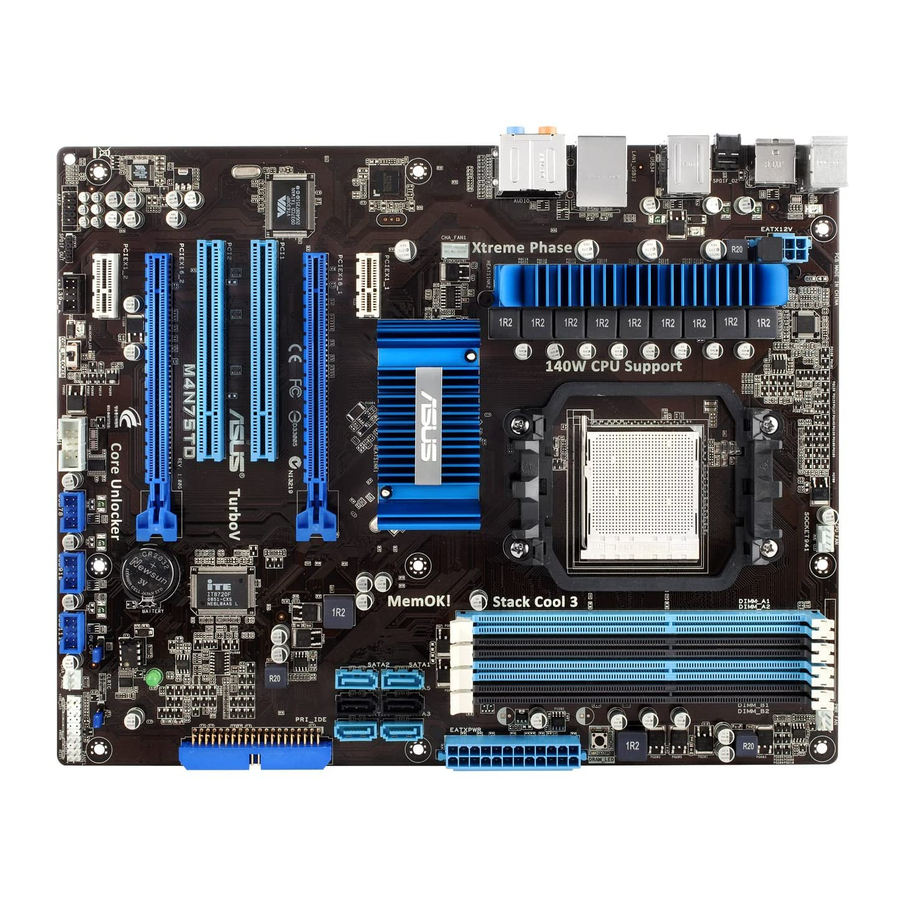
Page 17: Motherboard Layout
1.5.3 Motherboard layout 1.5.4 Layout contents Connectors/Jumpers/Slots Page ATX power connectors (24-pin EATXPWR, 8-pin EATX12V) 1-24 CPU socket AM3 CPU, Chassis and Power Fan connectors (4-pin CPU_FAN, 4-pin CHA_FAN1, 1-26 3-pin CHA_FAN2, 3-pin PWR_FAN) DDR3 DIMM slots MemOK! switch 1-18 Serial ATA connectors (7-pin SATA1-6) 1-25 IDE connector (40-1 pin PRI_IDE) -
Page 18: Central Processing Unit (Cpu)
Carefully insert the CPU into the socket until it fits in place. The CPU fits only in one correct orientation. DO NOT force the CPU into the socket to prevent bending the pins and damaging the CPU! Small triangle Gold triangle ASUS M4N75TD... -
Page 19: Installing The Heatsink And Fan
When the CPU is in place, push down the socket lever to secure the CPU. The lever clicks on the side tab to indicate that it is locked. Install a CPU heatsink and fan following the instructions that came with the heatsink package. You can also refer to section 1.6.2 Installing the heatsink and fan for instructions. - Page 20 When the fan and heatsink assembly is in place, connect the CPU fan cable to the connector on the motherboard labeled CPU_FAN. Do not forget to connect the CPU fan connector! Hardware monitoring errors can occur if you fail to plug this connector. ASUS M4N75TD...
-
Page 21: System Memory
System memory 1.7.1 Overview The motherboard comes with four Double Data Rate 3 (DDR3) Dual Inline Memory Modules (DIMM) sockets. A DDR3 module has the same physical dimensions as a DDR2 DIMM but is notched differently to prevent installation on a DDR2 DIMM socket. DDR3 modules are developed for better performance with less power consumption. - Page 22 M4N75TD Motherboard Qualified Vendors Lists (QVL) DDR3-1600MHz capability DIMM socket support (Optional) Chip Chip Vendor Part No. Size Timing Voltage Brand 1 DIMM 2 DIMM 4 DIMM A-DATA AX3U1600PB1G8-2P 2GB(2 x 1GB) SS - 8-8-8-24 1.65-1.85 • • • A-DATA...
- Page 23 DDR3-1333MHz capability DIMM socket support Chip (Optional) Vendor Part No. Size Chip NO. Timing Voltage Brand 1 DIMM 2 DIMM 4 DIMM A-DATA AD3133301GOU SS A-DATA AD30908C8D-15IG • A-DATA AD31333002GOU DS A-DATA AD30908C8D-15IG • • A-DATA AD3U1333B2G9-2 DS A-DATA AD30908C8D-15IG •...
- Page 24 6GB(3 x 2GB) DS - 9-9-9-24 1.65 • • Silicon SP001GBLTU1333S01 SS NANYA NT5CB128M8AN-CG • • Power Silicon SP001GBLTU133S02 SS S-POWER I0YT3E0 • Power Silicon SP002GBLTU133S02 DS S-POWER I0YT3E0 • • • Power UMAX E41302GP0-73BDB DS UMAX U2S24D30TP-13 • • 1-12 ASUS M4N75TD...
- Page 25 Dual-channel memory configuration. • C*: Supports four modules inserted into both the blue slots and the black slots as two pairs of Dual-channel memory configuration. Visit the ASUS website for the latest QVL. Chapter 1: Product introduction 1-13...
-
Page 26: Installing A Dimm
DIMM. Locked Retaining Clip Always insert the DIMM into the socket VERTICALLY to prevent DIMM notch damage. 1.7.4 Removing a DIMM Press the retaining clip outward to unlock the DIMM. Remove the DIMM from the socket. 1-14 ASUS M4N75TD... -
Page 27: Expansion Slots
Expansion slots In the future, you may need to install expansion cards. The following sub-sections describe the slots and the expansion cards that they support. Unplug the power cord before adding or removing expansion cards. Failure to do so may cause you physical injury and damage motherboard components. -
Page 28: Jumpers
• Due to the chipset behavior, AC power off is required to enable C.P.R. function. You must turn off and on the power supply or unplug and plug the power cord before rebooting the system. 1-16 ASUS M4N75TD... - Page 29 CPU overvoltage setting (3-pin OV_CPU) This jumper allows you to enable or disable the advanced CPU overvoltage setting in BIOS. Read the following information before you change the jumper setting. Set to pins 1-2 to activate the advanced CPU overvoltage feature. OV_CPU Pins 2-3 (Default) 0.80V –...
-
Page 30: Onboard Switches
If the installed DIMMs still fail to boot after the whole tuning process, the DRAM_LED lights continuously. Replace the DIMMs with ones recommended in the Memory QVL (Qualified Vendors Lists) in this user manual or on the ASUS website at www.asus.com. -
Page 31: Onboard Leds
Core Unlocker switch This switch allows you to unlock the extra cores of your CPU. For ensuring the system performance, turn the switch setting to Enable when the system is powered off. • The UNCLOCKER_LED near the Core Unlocker switch lights when the switch setting is turned to Enable. - Page 32 , the LED next to the error device will continue lighting until the problem is solved. This user-friendly design provides an intuitional way to locate the root problem within a second. Core Unlocker LED The Core Unlocker LED lights when the Core Unclocker switch is turned to Enable. 1-20 ASUS M4N75TD...
-
Page 33: Connectors
1.12 Connectors 1.12.1 Rear panel connectors PS/2 mouse port (green). This port is for a PS/2 mouse. IEEE 1394a port. This 6-pin IEEE 1394a port provides high-speed connectivity for audio/video devices, storage peripherals, PCs, or portable devices. LAN (RJ-45) port. This port allows Gigabit connection to a Local Area Network (LAN) through a network hub. - Page 34 Optical S/PDIF Out port. This port connects an external audio output device via an optical S/PDIF cable. USB 2.0 ports 5 and 6. These 4-pin Universal Serial Bus (USB) ports are available for connecting USB 2.0 devices. PS/2 keyboard port (purple). This port is for a PS/2 keyboard. 1-22 ASUS M4N75TD...
-
Page 35: Internal Connectors
1.12.2 Internal connectors IDE connector (40-1 pin PRI_IDE) The onboard IDE connector is for Ultra DMA 133/100/66 signal cable. There are three connectors on each Ultra DMA 133 / 100 / 66 signal cable: blue, black, and gray. Connect the blue connector to the motherboard’s IDE connector, then select one of the following modes to configure your devices: Drive jumper setting Mode of device(s) - Page 36 • If you are uncertain about the minimum power supply requirement for your system, refer to the Recommended Power Supply Wattage Calculator at http://support.asus. com/PowerSupplyCalculator/PSCalculator.aspx?SLanguage=en-us for details. • If you want to use two or more high-end PCI Express x16 cards, use a PSU with 1000W power or above to ensure the system stability.
- Page 37 NVIDIA nForce 750a SLI Serial ATA connectors (7-pin SATA1-6) ® ® These connectors are for the Serial ATA signal cables for Serial ATA 3Gb/s hard disk and optical disk drives. The Serial ATA 3Gb/s is backward compatible with Serial ATA 1.5Gb/s specification.
- Page 38 • The CPU_FAN connector supports the CPU fan of maximum 1A (12 W) fan power. • Only the CPU_FAN, CHA_FAN1 and CHA_FAN2 connectors support the ASUS Fan Xpert feature. • If you install two VGA cards, we recommend that you plug the rear chassis fan cable to the motherboard connector labeled CHA_FAN1 or CHA_FAN2 for better thermal environment.
-
Page 39: System Panel Connector (20-8 Pin Panel)
System panel connector (20-8 pin PANEL) This connector supports several chassis-mounted functions. • System power LED (2-pin PLED) This 2-pin connector is for the system power LED. Connect the chassis power LED cable to this connector. The system power LED lights up when you turn on the system power, and blinks when the system is in sleep mode. - Page 40 Never connect a 1394 cable to the USB connectors. Doing so will damage the motherboard! The USB 2.0 module is purchased separately. Digital audio connector (4-1 pin SPDIF_OUT) This connector is for an additional Sony/Philips Digital Interface (S/PDIF) ports. The S/PDIF module is purchased separately. 1-28 ASUS M4N75TD...
- Page 41 Front panel audio connector (10-1 pin AAFP) This connector is for a chassis-mounted front panel audio I/O module that supports either High Definition Audio or AC`97 audio standard. Connect one end of the front panel audio I/O module cable to this connector. •...
- Page 42 This connector is for an IEEE 1394a port. Connect the IEEE 1394a module cable to this connector, then install the module to a slot opening at the back of the system chassis. Never connect a USB cable to the IEEE 1394a connector. Doing so will damage the motherboard! 1-30 ASUS M4N75TD...
-
Page 43: Software Support
ASUS website at www.asus.com for updates. • For detailed software instructions, see the Manual folder in the Support DVD or download the latest software manual from the ASUS website at www.asus.com. To run the Support DVD Place the Support DVD to the optical drive. The DVD automatically displays the Drivers menu if Autorun is enabled in your computer. -
Page 44: Nvidia ® Sli™ Technology Support
PCIEX16 slots. If your motherboard has more than two PCIEX16 slots, refer to Chapter 2 in this user manual for the locations of the PCIEX16 slots recommended for multi-graphics card installation. Ensure that the cards are properly seated on the slots. 1-32 ASUS M4N75TD... -
Page 45: Installing The Device Drivers
Align and firmly insert the SLI bridge connector to the goldfingers on each graphics card. Ensure that the connector is firmly in place. Connect two independent auxiliary power sources from the power supply to the two graphics cards separately. Connect a VGA or a DVI cable to the graphics card. SLI bridge Goldfingers Installing the device drivers... - Page 46 B1. If you cannot see the NVIDIA Control Panel item in step (A), select Personalize. B2. From the Personalization window, select Display Settings. B3. From the Display Settings dialog box, click Advanced Settings. 1-34 ASUS M4N75TD...
- Page 47 B4. Select the NVIDIA GeForce tab, and then click Start the NVIDIA Control Panel. B5. The NVIDIA Control Panel window appears. Enabling SLI settings From the NVIDIA Control Panel window, select Set SLI Configuration. Click Enable SLI and set the display for viewing SLI rendered content.
-
Page 48: Nvidia Hybrid Sli™ Technology
• HybridPower requires displays to be connected to the mGPU. HybridPower cannot be enabled when displays are driven through the dGPU. • HybridPower and GeForce Boost are supported by certain set of dGPUs. Go to www.nvidia.com/hybridsli to learn the supported GPUs. 1-36 ASUS M4N75TD... - Page 49 The Hybrid SLI icon indicates that the system is in Performance mode and that GeForce Boost is enabled. The onboard GPU will share the rendering load with the dGPU and boost the performance of the dGPU. Visit www.asus.com for the latest chipset driver. Chapter 1: Product introduction 1-37...
- Page 50 When the Power Saving mode is enabled, the dGPU does not show in the Windows ® Device Manager. Power Saving mode is disabled. When the Power Saving mode is enabled, the dGPU is turned off and does not appear in the Device Manager. 1-38 ASUS M4N75TD...
-
Page 51: Knowing Bios
Refer to the corresponding sections for details on these utilities. Save a copy of the original motherboard BIOS file to a USB flash drive in case you need to restore the BIOS in the future. Copy the original motherboard BIOS using the ASUS Update utility. -
Page 52: Asus Update Utility
2.2.1 ASUS Update utility The ASUS Update is a utility that allows you to manage, save, and update the motherboard BIOS in Windows environment. ® • ASUS Update requires an Internet connection either through a network or an Internet Service Provider (ISP). -
Page 53: Asus Ez Flash 2 Utility
2.2.2 ASUS EZ Flash 2 utility The ASUS EZ Flash 2 feature allows you to update the BIOS without having to use a bootable floppy disk or a DOS-based utility. Download the latest BIOS file from the ASUS website at www.asus.com. -
Page 54: Asus Crashfree Bios 3 Utility
The BIOS file in the motherboard support DVD may be older than the BIOS file published on the ASUS official website. If you want to use the newer BIOS file, download the file at support.asus.com and save it to a USB flash drive. -
Page 55: Bios Setup Program
• The BIOS setup screens shown in this section are for reference purposes only, and may not exactly match what you see on your screen. • Visit the ASUS website at www.asus.com to download the latest BIOS file for this motherboard. -
Page 56: Bios Menu Screen
• The BIOS setup screens shown in this chapter are for reference purposes only, and may not exactly match what you see on your screen. • Visit the ASUS website at www.asus.com to download the latest BIOS information. ASUS M4N75TD... -
Page 57: Navigation Keys
2.3.3 Navigation keys At the bottom right corner of a menu screen are the navigation keys for that particular menu. Use the navigation keys to select items in the menu and change the settings. Some of the navigation keys differ from one screen to another. 2.3.4 Menu items The highlighted item on the menu bar displays the specific items for that menu. -
Page 58: Main Menu
Selects the type of IDE drive. Setting to [Auto] allows automatic selection of the appropriate IDE device type. Select [CDROM] if you are specifically configuring a CD-ROM drive. Select [ARMD] (ATAPI Removable Media Device) if your device is either a ZIP, LS-120, or MO drive. Configuration options: [Not Installed] [Auto] [CDROM] [ARMD] ASUS M4N75TD... -
Page 59: Sata 1-4
LBA/Large Mode [Auto] Enables or disables the LBA mode. Setting to [Auto] enables the LBA mode if the device supports this mode, and if the device was not previously formatted with LBA mode disabled. Configuration options: [Disabled] [Auto] Block (Multi-Sector Transfer) M [Auto] Enables or disables data multi-sectors transfers. -
Page 60: Storage Configuration
This menu gives you an overview of the general system specifications. The BIOS automatically detects the items in this menu. BIOS Information Displays the auto-detected BIOS information. Processor Displays the auto-detected CPU specification. System Memory Displays the auto-detected system memory. 2-10 ASUS M4N75TD... -
Page 61: Ai Tweaker Menu
Ai Tweaker menu The Ai Tweaker menu items allow you to configure overclocking-related items. Take caution when changing the settings of the Ai Tweaker menu items. Incorrect field values can cause the system to malfunction. The default values of the following items vary depending on the CPU and memory modules you install on the motherboard. -
Page 62: Dram Frequency
Configuration options: [Auto] [3 CLK] – [17 CLK] DRAM WRITE to READ Delay(DD) [Auto] Configuration options: [Auto] [2 CLK] – [10 CLK] DRAM WRITE to READ Delay(SD) [Auto] Configuration options: [Auto] [4 CLK] [5 CLK] [6 CLK] [7 CLK] 2-12 ASUS M4N75TD... -
Page 63: Dram Driving Configuration
DRAM WRITE to WRITE Timing [Auto] Configuration options: [Auto] [3 CLK] – [10 CLK] DRAM READ to READ Timing [Auto] Configuration options: [Auto] [3 CLK] – [10 CLK] DRAM REF Cycle Time [Auto] Configuration options: [Auto] [90ns] [110ns] [160ns] [300ns] [350ns] DRAM Refresh Rate [Auto] Configuration options: [Auto] [Every 7.8ms] [Every 3.9ms] DRAM Command Rate [Auto]... -
Page 64: Cpu/Nb Voltage
PCI Spread Spectrum [Disabled] This item becomes user-configurable only when you set the SATA Spread Spectrum item to [Linear Down]. We recommend that you leave this item to its default setting for system stability. Configuration options: [Disabled] [Linear Down] 2-14 ASUS M4N75TD... -
Page 65: Advanced Menu
Advanced menu The Advanced menu items allow you to change the settings for the CPU and other system devices. Be cautious when changing the settings of the Advanced menu items. Incorrect field values can cause the system to malfunction. BIOS SETUP UTILITY Main Ai Tweaker Advanced... -
Page 66: Chipset
Disables or sets the L2/L3 Cache BG Scrub. This item allows the L2/L3 Data Cache RAM to be corrected when idle. Configuration options: [Disabled] [40ns] [80ns] [160ns] [320ns] [640ns] [1.28us] [2.56us] [5.12us] [10.2us] [20.5us] [41.0us] [81.9us] [163.8us] [327.7us] [655.4us] [1.31ms] [2.62ms] [5.24ms] [10.49ms] [20.97ms] [42.00ms] [84.00ms] 2-16 ASUS M4N75TD... -
Page 67: Onboard Devices Configuration
SouthBridge Configuration Hybrid SLI support [Disabled] Allows you to enable or disable the Hybrid SLI function if you install a Hybrid SLI-support graphics card. Configuration options: [Auto] [Disable]. Primary Graphics Adapter [PCIE VGA Card First] Allows you to select which graphics controller to use as the primary boot device. Configuration options: [PCI VGA Card First] [PCIE VGA Card First] PCIE training [Gen2 if supported] Configuration options: [Only Gen1] [Gen2 if supported]... -
Page 68: Usb Configuration
If detected, the USB controller legacy mode is enabled. If no USB device is detected, the legacy USB support is disabled. Configuration options: [Disabled] [Enabled] [Auto] USB 2.0 Controller Mode [HiSpeed] Allows you to configure the USB 2.0 controller in HiSpeed (480 Mbps) or Full Speed (12 Mbps). Configuration options: [FullSpeed] [HiSpeed] 2-18 ASUS M4N75TD... -
Page 69: Power Menu
Power menu The Power menu items allow you to change the settings for the Advanced Configuration and Power Interface (ACPI) and the Advanced Power Management (APM). Select an item then press <Enter> to display the configuration options. BIOS SETUP UTILITY Main Ai Tweaker Advanced... - Page 70 [Optimal], the Chassis fan automatically adjusts depending on the Chassis temperature. Set this item to [Silent] to minimize fan speed for quiet Chassis fan operation, or [Performance] to achieve the maximum Chassis fan speed. Configuration options: [Performance] [Optimal] [Silent] 2-20 ASUS M4N75TD...
-
Page 71: Boot Menu
This allows you to enable or disable the full screen logo display feature. Configuration options: [Disabled] [Enabled] Set this item to [Enabled] to use the ASUS MyLogo 2™ feature. AddOn ROM Display Mode [Force BIOS] Sets the display mode for option ROM. Configuration options: [Force BIOS] [Keep Current] Bootup Num-Lock [On] Allows you to select the power-on state for the NumLock. -
Page 72: Security
On the password box that appears, type a password composed of at least six letters and/or numbers, then press <Enter>. Confirm the password when prompted. The message “Password Installed” appears after you set your password successfully. To change the user password, follow the same steps as in setting a user password. 2-22 ASUS M4N75TD... -
Page 73: Tools Menu
(C)Copyright 1985-2009, American Megatrends, Inc. 2.9.1 ASUS EZ Flash 2 Allows you to run ASUS EZ Flash 2. When you press <OK>, a confirmation message appears. Use the left/right arrow key to select between [Yes] or [No], then press <OK> to confirm your choice. -
Page 74: Asus O.c. Profile
The first time wizard will run again when you enter the Express Gate environment after clearing its settings. 2.9.3 ASUS O.C. Profile This item allows you to store or load multiple BIOS settings. Add Your CMOS Profile. Allows you to save the current BIOS file to the BIOS Flash. In the Name sub-item, type your profile name and press <Enter>, and then choose a profile number to save your CMOS... -
Page 75: Exit Menu
2.10 Exit menu The Exit menu items allow you to load the optimal or failsafe default values for the BIOS items, and save or discard your changes to the BIOS items. BIOS SETUP UTILITY Main Ai Tweaker Advanced Power Boot Tools Exit Exit Options... - Page 76 2-26 ASUS M4N75TD...
-
Page 77: Asus Contact Information
+1-812-282-3777 +1-510-608-4555 Web site usa.asus.com Technical Support Telephone +1-812-282-2787 Support fax +1-812-284-0883 Online support support.asus.com ASUS COMPUTER GmbH (Germany and Austria) Address Harkort Str. 21-23, D-40880 Ratingen, Germany +49-2102-959911 Web site www.asus.de Online contact www.asus.de/sales Technical Support Telephone +49-1805-010923 Support Fax...
Need help?
Do you have a question about the M4N75TD and is the answer not in the manual?
Questions and answers