
Summary of Contents for Eclipse Combustion 6500
- Page 1 Instruction Manual No. 826, 05/03 Bi-Flame Dual Burner Monitoring System Model 6500 Version 1.8...
-
Page 2: Disclaimer Notice
Eclipse Combustion’s products. Eclipse Combustion, for a period of one year from shipment, warrants each Bi-Flame burner monitoring system to the original purchaser to be free from defects in material and workmanship under normal use as defined hereafter. -
Page 3: About This Manual
• Obey all the safety instructions. • Do not deviate from any instructions or application limits in this manual without written consent from Eclipse Combustion. • If you do not understand any part of the information in this manual, do not continue. Contact your Eclipse sales office or Eclipse Combustion. -
Page 4: Table Of Contents
Table of Contents About this manual Table of contents Introduction Product Description ... Specifications Introduction ... Specifications ... Dimensions ... Modules Description Introduction ... Module Description and Identification ... Relay Module ... Logic Module ... Power Module ... Sensor Module ... Remote Display ... - Page 5 Valve Leak Sensing Device ... Remote Display Unit ... RS232/RS485 Communication Interfaces ... Logic Module Status Lights & Push-buttons ... Limits ... Air ... Purge ... Burner On ... Fault ... Alarm ... Low Fire ... High Fire ... Scan ... Enter ...
- Page 6 Sensor Installation Introduction ... Sensor Wiring ... Flame Rods ... Scanners ... Scanner Sighting Considerations ... Test Procedures ... Introduction ... Flame Signal Strength ... Minimum Pilot Test... Pilot Flame Failure Test ... Main Flame Failure Test ... Spark Sighting Test ... Limits &...
-
Page 7: Introduction
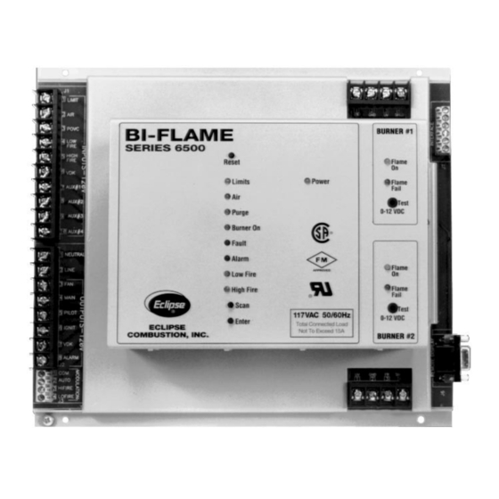
Introduction RODUCT ESCRIPTION The Eclipse Combustion Bi-Flame Burner Monitoring System controls the start-up sequence and monitors the flame of two individual gas, oil, or combination gas/oil burners connected to a common valve train. Its dynamic on-board testing checks for faulty relays, proof of valve closure, high and low fire switch interlocks, and shorted air switch. -
Page 8: Specifications
This section gives a detailed overview of Bi-Flame specifications and dimensions. Description •120 VAC (+10%, -15%), 50/60 Hz standard. Internal power consumption: 24VA Unit Model Nos. Bi-Flame 6500 90˚ U.V. Scanner 5600-90A U.V. Scanner 5600-91 NEMA4 UV Scanner 5600-91N4 Self-Check U.V. -
Page 9: Dimensions
IMENSIONS Main Chassis Mounting Holes (4) 5 mm (3/16") Dia. 270 mm (10-5/8") Remote Display (Shown with remote keypad and reset) 102 mm (4") Square 183 mm (7-3/16") 237 mm (9-5/16") 229 mm 21 mm (9") (13/16") 54 mm (2-1/8") Mounting Bracket &... -
Page 10: Modules Description
Logic Module Location Power Module Location In this section, you will find descriptions of the various modules which comprise the Bi-Flame dual burner flame monitoring system, whether standard or optional items. Relay Module The relay module contains the output relays which provide power for operating the ignition coil, pilot valve, main valve, combustion fan and alarm. -
Page 11: Sensor Module
The sensor module incorporates test point connection jacks in the front of the unit. Using these, the flame signal strength of each burner a 0-15 VDC, one megohm/volt meter can be measured using Sensor Module Location explained and shown in “Flame Signal Strength”... -
Page 12: Dip Switch Selection
DIP Switch Selection NTRODUCTION SWITCH LOCATION SWITCH ACCESS This section details the location, selection and description of the Bi-Flame DIP switches, which allow for sequence and timing func- tions as well as system configuration. Caution: To avoid electric shock, shut off the power supply when installing any control device. -
Page 13: S2 Dip Switch Settings
SW1: Recycling mode selection (On=Recycling; Off=Non-recycling) SW2: Pilot selection (On= Intermittent, where pilot remains on during burner cycle; Off =Interrupted, where pilot valve closes after main burner is established). SW3: Trial-for-ignition (TFI) range selection; used with SW7 of the S4 DIP switch. -
Page 14: Function Summary
Combustion Air Flow Check Terminal The Bi-Flame checks that the combustion air flow switch is open be- fore start-up, closed during operation and open again at burner shut- down, thus preventing operation with an air switch that is defective, maladjusted or jumpered. -
Page 15: Recycle Mode
Note: Both pilots must light within the specified TFI or a pilot flame failure will occur. If one burner experiences either a pilot or main flame failure, then both burners will shut down. The failed burner will be indicated by the red “Flame Fail” light. -
Page 16: Auxiliary Inputs
Auxiliary Inputs This feature provides four auxiliary inputs which are monitored by the Bi-Flame as alarm interlocks. This means that when the input voltage is interrupted, the system locks out and will annunciate on the optional remote display unit. A voltage of 120 VAC must be present at the input for the Bi-Flame system to operate. -
Page 17: Modulation Contacts
The Automatic step occurs 20 seconds after the main output has energized (see Table 10.1 beginning on page 36) and allows the burner firing rate to be controlled by an automatic temperature controller. Eclipse Bi-Flame v1.8, Instruction Manual 826, 05/03... -
Page 18: Valve Leak Sensing Device
Valve Leak Sensing Device (VLSD) Interface The Bi-Flame Valve Leak Sensing Device (VLSD or VDK) interface provides a 120 VAC output which triggers the start of the test pe- riod. An input is also provided which receives a 120 VAC signal from the VLSD. -
Page 19: Remote Display Unit
This LED illuminates when the operation limits are made. These limits are wired in series to terminal J1-1. This input becomes energized to begin the burner sequence. When in the test mode, this LED flashes (see “Pilot Test Mode” on page 15). -
Page 20: Air
Purge This LED illuminates whenever the combustion blower is energized, including the purge period and the main burner period of the se- quence. It blinks on and off while the purge is in process and remains constant when the purge process is complete. -
Page 21: System Faults
1) If a flame is detected out of sequence, which may be caused by: a) a faulty scanner b) electrical interference on the sensor leads c) a flame exists in the burner due to a gas leak or other condition. 2) Air flow switch closed before start-up. System Lockout Conditions... -
Page 22: System Installation
The interlocks and limit switches are wired in series. A break in this circuit will shut the burner down, but will not produce an alarm. This input is considered the normal operation control input to the Bi-Flame system. -
Page 23: Ignition Wiring
The system can be wired to check for the proof of valve closure (POVC) switch on the main gas valve prior to start-up and after the end of the burner cycle. To use this feature the POVC switch must be connected to the POVC switch input (terminal 3 on terminal strip J1). -
Page 24: Remote Reset
EMOTE RESET EMOTE DISPLAY This feature permits remote mounting of a switch to reset the Bi- Flame. To use this feature, a normally closed remote reset switch must be wired between terminals 1 and 4 on terminal strip J7. When it is depressed or actuated, the connection between the terminals is momentarily interrupted and resets the Bi-Flame. -
Page 25: Terminal Strips Identification & Location (Figure 6.1)
Figure 6.1 Terminal Strips Identification & Location Main Chassis Remote Display Connection Eclipse Bi-Flame v1.8, Instruction Manual 826, 05/03... -
Page 26: Wiring Diagram & Connections-Main Chassis (Figure 6.2)
Terminals Temperature Controller Common P1-1 4 to 20 mA Auto P1-2 High Fire Low Fire P1-4 Terminals RS 232 Burner #1 Remote Reset Pushbutton (if required) 120 VAC Neutral 5602-91 U.V. Signal (UV) Self-Check GND (Return) Scanner When not used, must be tied into 120 VAC. -
Page 27: Sensor Installation
Be certain that the flame sensor detects only pilot and main flames, not glowing refractory, burner or ignition parts. Route sensor wiring a sufficient distance from ignition and other high voltage or high current wiring to avoid electrical interference. -
Page 28: Flame Rods
3) Provide a burner/flame grounding area that is at least four times greater than the flame rod area contacting the flame. The flame rod/burner ground ratio and position of the rod in the flame may need adjustment to yield maximum flame signal strength. -
Page 29: Scanner Sighting Considerations
Line U.V. Scanner Sighting Aim scanners at the third of the flame closest to the burner nozzle, as shown at left. This is especially true for oil flames which typically have less UV radiation in the outer flame. The scanner should view the in- tersection of the pilot and main flames. -
Page 30: Test Procedures
Run the following test procedures to ensure that the sensor will not detect a pilot flame too small to reliably light the main flame: 1) Manually shut off the fuel supply to the burner, but not to the pi- lot. -
Page 31: Pilot Flame Failure Test
Operating a system with defective safety equipment can cause explosions, injuries, and property damage. The burner at which a flame fails will be identified by the red “Flame Fail- ure” LED on the cover. Eclipse Bi-Flame v1.8, Instruction Manual 826, 05/03... -
Page 32: Maintenance & Troubleshooting
4. Test interlock sequence of all safety equipment as described in Test Procedures: manually make each interlock fail, noting what related equipment closes or stops as specified by the manufac- turer. Test flame safeguard by manually shutting off gas to the burner. Eclipse Bi-Flame v1.8, Instruction Manual 826, 05/03... -
Page 33: Yearly Checklist
4. Make sure that the following components are not damaged or distorted: • the burner nozzle • the spark plugs • the flame sensors • the flame tube or combustion block of the burner Eclipse Bi-Flame v1.8, Instruction Manual 826, 05/03... -
Page 34: Troubleshooting
Cannot initiate start sequence Scrambled messages on remote display. “UNSAFE AIR SHORT” message appears on display. Burner flame fails but no flame failure indication occurs. POSSIBLE CAUSE • Main valve is not closed. • Air pressure switch has not made contact. -
Page 35: Remote Display Messages
Remote Display Messages NTRODUCTION This section covers how the optional remote display is used with the Bi-Flame. The remote display provides LCD messages which monitor the status of the Bi-Flame’s functions as well as any lock- out conditions. This section is divided into two parts or tables: •... -
Page 36: Bi-Flame Operating Sequence (Table 10.1)
SAFE START OK VX.X CS=XXXX NORMAL MESSAGE FAN ENERGIZED Fan output is energized; modu- lator is sent to low fire. BURNER START-UP (see next page) Table 10.1 Bi-Flame Operating Sequence POWER ON Was internal safe start check successful? EXTERNAL INTERLOCK CHECKS... - Page 37 Is flame signal present? Is flame signal present? (see next page) Eclipse Bi-Flame v1.8, Instruction Manual 826, 05/03 ERROR MESSAGE PILOT # (0X) FAILED LKOUT XXXX:XX:XX X = burner number. ERROR MESSAGE MAIN # (0X) FAILED LKOUT XXXX:XX:XX X = burner number.
- Page 38 NORMAL MESSAGE FLAME #(OX) XX.XV TIME = XXXX:XX:XX Flame signal = XX.X Volts DC; (X) = Number of burner being monitored; the Bi-Flame will scroll through each burner con- tinuously during the burner-on cycle. Eclipse Bi-Flame v1.8, Instruction Manual 826, 05/03...
-
Page 39: Burner Shutdown
. . . ERROR MESSAGE #2 – 30 SECONDS AFTER #1 UNSAFE AIR SHORT LKOUT XXXX:XX:XX Alarm energized. BURNER SHUTDOWN Shutdown is started by opening the operating interlock circuit. Is voltage present at interlocks? Is proof of closure circuit closed? -
Page 40: Internal Fault
Main flame lost during operation in the automatic modulation mode. Burner number (X) given of failed unit. Status Main flame of burner number (Y) is proven in the automatic modula- tion mode; flame strength is XX.XV (volts DC). Elapsed time is shown in hours:minutes:seconds. - Page 41 LKOUT XXXX:XX:XX TYPE EXPLANATION Main flame was not established during the main burner trial for ignition. Main valve has been energized and main flame proven during trial for ignition. Pilot valve (strip J2, terminal 5) is de-energized and main flame is on.
- Page 42 Table 10.2 Remote Display Diagnostic Messages (continued) MESSAGE UNSAFE FLAME ON UNSAFE FLAME ON LKOUT XXXX:XX:XX UNSAFE–FLM–PURGE UNSAFE–FLM–PURGE LKOUT XXXX:XX:XX VALVE LEAKAGE UNDER TEST XX VALVE LEAK FAIL LKOUT XXXX:XX:XX WATCHDOG FAIL LKOUT XXXX:XX:XX XXXXXXX XXXXXTESTXX TYPE EXPLANATION Hold Flame signal—actual, induced, or faulty scanner—is detected be- fore start-up or after shutdown.
-
Page 43: Appendix
Appendix ONVERSION FACTORS Metric to English. cubic meter (m cubic foot (ft cubic meter/hour (m cubic foot/hour (cfh) degrees Celsius (°C) degrees Fahrenheit (°F) kilogram (kg) pound (lb) kilowatt (kW) meter (m) millibar (mbar) inches water column ("wc) millibar (mbar) pounds/sq in (psi) millimeter (mm) Metric to Metric. -
Page 44: Illustrated Parts List
LLUSTRATED ARTS Pos. Qty. Description Mother Board (6500M) Relay module circuit board Logic module circuit board Power module circuit board Sensor circuit board 183 cm (6ft) cable for remote display 305 cm (10ft) cable for remote display Remote display with keypad Downtimes due to a failure can be kept to a minimum by stocking recommended spares. - Page 45 Eclipse Bi-Flame v1.8, Instruction Manual 826, 05/03...
- Page 46 826 Instruction Manual 05/03...
Need help?
Do you have a question about the 6500 and is the answer not in the manual?
Questions and answers