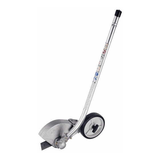
Echo POWER EDGER ATTACHMENT 99944200470 Operator's Manual
Power edger attachment
Hide thumbs
Also See for POWER EDGER ATTACHMENT 99944200470:
- Operator's manual (16 pages) ,
- Operator's manual (24 pages)
Table of Contents
Advertisement
Quick Links
Download this manual
See also:
Operator's Manual
Power Edger Attachment
Operator's Manual
MODEL
MODELS USED ON:
Read rules for safe operation and instructions carefully. ECHO provides an
Operator's Manual and a Safety Manual Pro Attachment Series power source or Split
Boom Trimmer. Those manuals and this manual must be read and understood for
proper and safe operation, otherwise serious personal injury may result.
X7532278700
P
OWER
99944200470
S06000001001 - S06000057000
Serial Number 001001 - 057000
SRM-2100SB/2400SB
SRM-210SB/211SB
SRM-260SB/261SB
PAS 2100/2400
PAS 210/211
PAS 230/231
PAS 260/261
WARNING
E
A
DGER
TTACHMENT
O
'
M
PERATOR
S
DANGER
X753001210
08/02
1
ANUAL
Advertisement
Table of Contents

Subscribe to Our Youtube Channel
Summary of Contents for Echo POWER EDGER ATTACHMENT 99944200470
- Page 1 MODEL MODELS USED ON: Read rules for safe operation and instructions carefully. ECHO provides an Operator's Manual and a Safety Manual Pro Attachment Series power source or Split Boom Trimmer. Those manuals and this manual must be read and understood for proper and safe operation, otherwise serious personal injury may result.
-
Page 2: Table Of Contents
NTRODUCTION Welcome to the ECHO family. This ECHO product was designed and manufactured to provide long life and on-the-job- dependability. Read and understand this manual and the SAFETY MANUAL you found in the same package. You will find both easy to use and full of helpful operating tips and SAFETY messages. -
Page 3: Manual Safety Symbols And Important Information
If a decal cannot be read, a new one can be ordered from your ECHO Dealer. See PARTS ORDERING instructions for specific information. These decals are in English only:... -
Page 4: International Symbols
Carburetor adjustment 15 m (50 ft.) WARNING DANGER Hearing Protection ECHO recommends wearing hearing protection whenever unit is used. Proper Clothing Wear snug fitting, durable clothing; • Pants should have long legs, shirts with long sleeves. • DO NOT WEAR SHORTS, •... -
Page 5: Extended Operation/Extreme Conditions
EXTENDED OPERATION Vibration and Cold -- It is believed that a condition called Raynaud’s Phenomenon, which affects the fingers of certain individuals may be brought about by exposure to vibration and cold. Exposure to vibration and cold may cause tingling and burning sensations followed by loss of color and numbness in the fingers. -
Page 6: Safe Operation
Do not work in odd positions or on ladders. Do not over reach. ESCRIPTION After opening the carton, check for damage. Immediately notify your retailer or ECHO Dealer of damaged or missing parts. Use the contents list to check for missing parts. CONTENTS... -
Page 7: Specifications
PECIFICATIONS MODEL ----------------------------------------------------- POWER EDGER ATTACHMENT Shaft Length ------------------------------------------------ 845 mm (33.25in.) Attachment Width ----------------------------------------- 165.1 mm (6.50 in.) Attachment Height ---------------------------------------- 552.45 mm (21.75 in.) Weight w/blade -------------------------------------------- 2.3 kg (4.96 lb.) Drive Shaft Type ------------------------------------------- 6.35 mm (1/4 in.) Flex Shaft Rotation Direction ----------------------------------------- Clockwise viewed from right side Blade Length ----------------------------------------------- 203 mm (8 in.) -
Page 8: Operation
4. Rotate locator pin (A) 1/4 turn clockwise to engage lower shaft hole. Insure locator pin is fully engaged by twisting lower drive shaft. Locator pin should snap flush in coupler. Full engagement will prevent further shaft rotation. 5. Secure lower shaft assembly to coupler by tightening clamping knob (D). -
Page 9: Maintenance
If you are unsure or are not equipped with the necessary tools, you may want to take your unit to an ECHO Service Dealer for maintenance. To help you decide whether you want to DO-IT-YOURSELF or have the ECHO Dealer do it, each maintenance task has been graded. -
Page 10: Blade Replacement/Lubrication
BLADE REPLACEMENT Level 1. Tools Required: Scrench, Locking Tool, Needle Nose Pliers, 8 mm Open End Wrench, Grease Gun Parts Required: ECHO LUBE ® Grease, Blade P/N 69601552632 Gear Case NOTE Grease gear case every 50 hours of use. Replace blade when it is worn shorter than 6 in. - Page 11 Pull gear box and shield from drive shaft housing. 2. Pull flexible cable (C) from the drive shaft housing, wipe clean and re-coat with a thin coating [15 ml (1/2 oz.)] of ECHO 3. Slide the flexible cable (C) back in the drive housing. DO NOT get dirt on the flex cable.
-
Page 12: Servicing Information
• Sending a check or money order for $2.00 per Parts Catalog or $1.50 per Operator's Manual made payable to ECHO, INCORPORATED. State on a sheet of paper the model number and serial number of the ECHO unit you have, part number of the manual (if known), your name and address and mail to address above. -
Page 13: Supplement
This Supplement contains important information. Please keep with your Operator's Manual. Your unit was manufactured using Echo’s new open-face, all-metal blade guard, and improved heavy-duty gear case. Specification (Pg. 7) Gear Ratio ----------------------------- 2.07:1 Weight w/Blade ---------------------- 2.54 kg (5.6 lbs.) Maintenance (Pg.


Need help?
Do you have a question about the POWER EDGER ATTACHMENT 99944200470 and is the answer not in the manual?
Questions and answers