Table of Contents
Advertisement
I I N N D D U U S S T T R R I I A A L L D D U U T T Y Y C C O O M M M M E E R R C C I I A A L L D D O O O O R R O O P P E E R R A A T T O O R R
INTENDED FOR PROFESSIONAL
INSTALLATION ONLY
Visit www.LiftMaster.com to locate a professional installing dealer in your area.
2 Y E A R W A R R A N T Y
Serial # Box
Installation Date
O O W W N N E E R R ' ' S S M M A A N N U U A A L L
A SAFETY DEVICE IS HIGHLY RECOMMENDED
T T
L
3
ogic
This Operator Features
the Enhanced
PAT E N T P E N D I N G
The Maintenance Alert System™ allows the
installer to set an internal Maintenance
Cycle Counter. The Logic 3 operator
incorporates a self-diagnostic feature built
into the (MAS) Maintenance Alert System
LED. An LED on the 3-button station will
signal
when
the
set
number
cycles/months is reached or when the
operator requires immediate service.
Radio Receiver
Built on Board
315MHz
NOT FOR RESIDENTIAL USE
of
Advertisement
Table of Contents
Troubleshooting

Subscribe to Our Youtube Channel
Summary of Contents for Logic3 T
- Page 1 INTENDED FOR PROFESSIONAL Built on Board INSTALLATION ONLY Visit www.LiftMaster.com to locate a professional installing dealer in your area. 2 Y E A R W A R R A N T Y 315MHz Serial # Box NOT FOR RESIDENTIAL USE...
-
Page 2: Table Of Contents
T A B L E O F C O N T E N T S SPECIFICATIONS PROGRAMMING Carton Inventory ........3 Logic Control Pushbuttons . -
Page 3: Carton Inventory
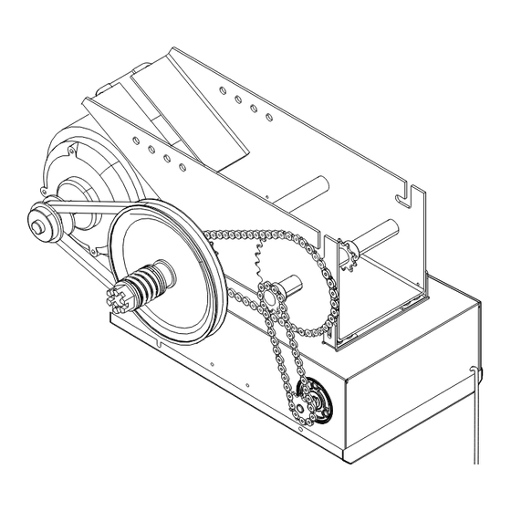
TROLLEY DRIVE CHAIN (#48 FOR 1/3 & 1/2 HP, #41 FOR 3/4 HP AND HIGHER) NOTE: The tracks are shipped separately. O P E R A T O R D I M E N S I O N S WEIGHTS AND DIMENSIONS HANGING WEIGHT: 80-110 LBS. -
Page 4: Operator Specifications
O P E R A T O R S P E C I F I C A T I O N S ELECTRICAL MOTOR TRANSFORMER: ..... . .24Vac Secondary TYPE:. -
Page 5: Preparation
WARNING WARNING P R E P A R A T I O N TRACK ASSEMBLY CAUTION WARNING WARNING 1. Using the 3/8"-16 x 3/4 " bolts and flange hex nuts provided, To prevent possible SERIOUS INJURY or DEATH: assemble the operator track by installing and tightening the •... -
Page 6: Installation
I N S T A L L A T I O N IMPORTANT NOTE: Before your operator is installed, be sure the door has been properly aligned and is working smoothly. The operator may be wall mounted or mounted on a bracket or shelf. If necessary, refer to the preparation on page 5. Refer to the illustrations and instructions below that suit your application. -
Page 7: Hang The Operator
I N S T A L L A T I O N HANG THE OPERATOR WARNING WARNING 1. The illustration below shows a typical method of hanging the operator from the ceiling. Each installation may vary, but in all To avoid possible SERIOUS INJURY from a falling operator, cases side braces should be used for additional strength. -
Page 8: Entrapment Protection Accessories
I N S T A L L A T I O N ENTRAPMENT PROTECTION ACCESSORIES WARNING WARNING (OPTIONAL) PHOTO EYES & SENSING EDGES To prevent possible SEVERE INJURY or DEATH, install reversing sensors when: CAUTION Sensing devices provided for door industry type operators with an •... -
Page 9: Adjustment
WARNING WARNING A D J U S T M E N T LIMIT SWITCH ADJUSTMENT CAUTION WARNING WARNING NOTE: Make sure the limit nuts are positioned between the limit switches before proceeding with adjustments. To avoid SERIOUS personal INJURY or DEATH from electrocution, disconnect electric power BEFORE manually 1. -
Page 10: Emergency Disconnect System
A D J U S T M E N T EMERGENCY DISCONNECT SYSTEM WARNING WARNING TO DISCONNECT DOOR FROM OPERATOR To prevent possible SERIOUS INJURY or DEATH from a falling The door should be in the fully closed position if possible. Pull... -
Page 11: Brake Adjustment
A D J U S T M E N T BRAKE ADJUSTMENT A solenoid brake is standard on 3/4 and 1 horsepower models, and is optional on 1/3 and 1/2 horsepower models. The brake is Brake Assembly adjusted at the factory and should not need additional adjustment for the the life of the brake assembly. -
Page 12: Safety Warnings
WARNING P O W E R W I R I N G & G R O U N D W I R I N G WARNING WARNING To reduce the risk of SEVERE INJURY or DEATH: • ALL electrical connections MUST be made by a qualified individual. -
Page 13: Control Station Wiring & Installation
C O N T R O L S T A T I O N W I R I N G A N D I N S T A L L A T I O N CONTROL WIRING CONNECTIONS WARNING WARNING 1. -
Page 14: Standard Power & Control Connection Diagrams
S T A N D A R D P O W E R & C O N T R O L C O N N E C T I O N D I A G R A M S OPEN... -
Page 15: Phase Wiring Diagram
L O G I C ( V E R . 3 . 0 ) 1 P H A S E W I R I N G D I A G R A M OPEN Maintenance CLOSE Alert LED (RD) (WH) STOP Open 3-Button... -
Page 16: Phase Wiring Diagram
L O G I C ( V E R . 3 . 0 ) 3 P H A S E W I R I N G D I A G R A M (BL/BK) (GY) (GY) (GY) OPEN (BR) (BR) (BR) (PU) (PU) -
Page 17: Logic Board
L O G I C B O A R D Ø14LGØ657–A Ø14GPØ657–A C3Ø Auxiliary Board Motor Direction Connections Jumper D3Ø2 P1Ø Single Phase & Three Phase Jumper POWER Programmed Chip TIMER J3ØØ TIMER Maintenance Alert DEFEAT DEFEAT System Button for Programming Maximum Run Timer Button... -
Page 18: Logic Control Pushbuttons
P R O G R A M M I N G LOGIC CONTROL PUSHBUTTONS OPEN, CLOSE, STOP SELECTOR DIAL Open, Close and Stop buttons are mounted directly on the logic board. Thus, making it easy to program as well as have door control at the electrical box. -
Page 19: Failsafe Wiring Types
To use the operator in any of the Failsafe wiring modes, or Timer Close. If the Timer To Close has been activated, the To Close wiring modes (TS, T, FSTS), a self monitoring safety open button and radio control can recycle the timer. -
Page 20: Programming Remotes
Ø14LGØ6 In C2 mode, operation is OPEN/STOP/constant pressure to CLOSE/STOP on release. In T and TS modes, operation is OPEN/STOP/CLOSE/REVERSE/STOP and Timer to Close start/refresh. NOTE: If Car Dealer mode is enabled, SBC will be open only stopping at the Open Mid-Stop. - Page 21 P R O G R A M M I N G REMOTE CONTROL PROGRAMMING FEATURE 3-BUTTON REMOTE CONTROLS Program Remote Controls from the 3-button control station Your 315MHz Security✚ ® or dip switch remote control can be (3BCS). programmed to operate as a 3-button wireless control station: the large button will open the door, the middle button will close Requires Firmware Version 4.6 or higher and a 3BCS with the the door, and the third button will stop the door’s movement.
-
Page 22: Maintenance Alert System (Mas)
P R O G R A M M I N G SELECTOR DIAL MAINTENANCE ALERT SYSTEM (MAS) Feature: An internal cycle counter will activate a flashing LED on the 3-button control station when the preset number of cycles or months has elapsed (whichever occurs first). Setting this feature is optional. -
Page 23: Mid Stop
The OPEN LED will flash once for every 5 seconds programmed and the CLOSE LED will flash once for every 60 seconds programmed. 7. Turn the selector dial to desired timer wiring type (TS ,T or FSTS). Example: To close the door after 70 seconds. Turn selector dial to... -
Page 24: Timer To Close
Dealer Mode is turned on) 5. Push the TIMER button and release. 6. Turn the SELECTOR DIAL to the desired wiring type (TS or T). NOTE: To disable the Dealer Mode follow steps 2 and 3, then press the MRT button and release (The GREEN TIMER LED will... -
Page 25: Automatically Learned Programming
A U T O M A T I C A L L Y L E A R N E D P R O G R A M M I N G AUXILIARY REVERSAL SYSTEM / RPM SENSOR Feature: This feature utilizes the RPM sensor connected to the... -
Page 26: Optional Programming
O P T I O N A L P R O G R A M M I N G RED/GREEN WARNING LIGHT CARD TIMER SETTING RED LAMP HOLDER RECEIVES POWER Feature: The Red/Green warning light card flashes a warning light... -
Page 27: Maintenance Shedule
M A I N T E N A N C E S C H E D U L E For use with Maintenance Alert System. Check at the intervals listed in the following chart: EVERY 3 MONTHS EVERY 6 MONTHS... -
Page 28: Troubleshooting
T R O U B L E S H O O T I N G DIAGNOSTIC CHART The logic board has several LEDs to assist in the installation and troubleshooting of the operator. The following chart should assist in verifying the operator is functioning properly. Turn the selector dial to DIAGNOSTIC to keep the door from moving while troubleshooting. -
Page 29: Troubleshooting Guide
TROUBLESHOOTING GUIDE FAULT POSSIBLE CAUSE ➤ THE OPERATOR WILL a) No power supply Verify primary line voltage from power source. ➤ NOT RESPOND TO ANY b) Operator control station is wired wrong Use the OPEN, CLOSE and STOP LEDs to help check correct wiring. COMMANDS Verify that the board is accepting commands by using the onboard station. -
Page 30: Troubleshooting Error Codes
TROUBLESHOOTING ERROR CODES Logic 3.0 operators incorporate a self diagnostic feature built into followed by a pause, an operator error has occurred. To view how the MAS LED. In addition to indicating when routing maintenance many errors currently exist, turn the selector dial to DIAGNOSTIC is due, the MAS LED can be used to troubleshoot some problems and press the OPEN button. -
Page 31: Troubleshooting Radio Functionality
TROUBLESHOOTING RADIO FUNCTIONALITY The error codes will display at the radio LED. NOTE: Radio receiver is compatible with 315MHz remotes ERROR CODE SYMPTOM DISPLAY POSSIBLE PROBLEM CORRECTION No response from the remote Quick Flash Unlearned remote - Try re-learning the A user tries to use a remote, remote (page 20). -
Page 32: Electrical Box
E L E C T R I C A L B O X (K72-12515-1) (K72-10047-1) - Page 33 E L E C T R I C A L B O X L O G I C ( V E R 3 . 0 ) For replacement of electrical box, motor or brake components be sure to match model number of your unit to kit number below to ensure proper voltage requirements.
- Page 34 M O D E L T (K72-12508 K72-12509) K5 (K75-12870) (71-B120 71-B240) (K72-12507 K72-12506) (K75-10177)
-
Page 35: Repair Parts Kits
R E P A I R P A R T S K I T S - M O D E L T SERVICE KITS INDIVIDUAL PARTS ITEM PART # DESCRIPTION ITEM PART # DESCRIPTION 71-B120 Brake kit - 115 Volt models... -
Page 36: Control Connection Diagram
C O N T R O L C O N N E C T I O N D I A G R A M IMPORTANT NOTES: 1. The 3-Button Control Station provided must be connected for operation. 2. If a STOP button is not used, a jumper must be placed between terminals 4 and 5.
Need help?
Do you have a question about the T and is the answer not in the manual?
Questions and answers