Table of Contents
Advertisement
Quick Links
PIX 525
This chapter guides you through the installation of the PIX 525, and includes the following sections:
•
•
•
•
•
•
•
•
•
•
PIX 525 Product Overview
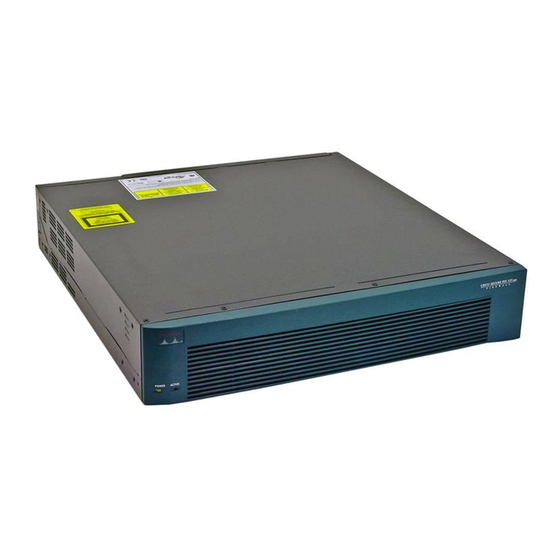
Figure 6-1
Figure 6-1
POWE R
ACTIV E
78-15170-02
PIX 525 Product Overview, page 6-1
Installing the PIX 525, page 6-3
PIX 525 Feature Licenses, page 6-5
Installing Failover, page 6-6
Installing LAN-Based Failover, page 6-8
Replacing a Lithium Battery, page 6-12
Installing a Memory Upgrade, page 6-12
Installing a Circuit Board in the PIX 525, page 6-15
Installing a DC Power Supply, page 6-19
show the front view of the PIX 525.
PIX 525 Front Panel
C H A P T E R
CISC O SECU RITY PIX
525
SERIES
F I R E W A L L
Cisco PIX Security Appliance Hardware Installation Guide
6
6-1
Advertisement
Table of Contents

Related Manuals for Cisco PIX-525-UR-BUN - PIX 525 Unrestricted Bundle


Summary of Contents for Cisco PIX-525-UR-BUN - PIX 525 Unrestricted Bundle
-
Page 1: Table Of Contents
PIX 525. Figure 6-1 PIX 525 Front Panel CISC O SECU RITY PIX SERIES F I R E W A L L POWE R ACTIV E Cisco PIX Security Appliance Hardware Installation Guide 78-15170-02... -
Page 2: Pix 525 Product Overview
Off when the unit is in standby mode. There are three LEDs for the each RJ-45 interface port and three types of fixed interface connectors on the back of the PIX 525. Cisco PIX Security Appliance Hardware Installation Guide 78-15170-02... -
Page 3: Installing The Pix 525
Attach the brackets to the holes near the front of the unit on each side of the PIX 525 using the supplied screws. Attach the unit to the equipment rack. Cisco PIX Security Appliance Hardware Installation Guide 78-15170-02... - Page 4 “Installing a Memory Upgrade” section on page 6-12 for more information. Note It is not necessary to remove the chassis cover of the PIX 525 to access the circuit boards or memory. Cisco PIX Security Appliance Hardware Installation Guide 78-15170-02...
- Page 5 For information on upgrading feature licenses or downloading the latest software versions, refer to the configuration guide online http://www.cisco.com/en/US/docs/security/pix/pix63/configuration/guide/config.html This section includes the following topics: VPN Accelerator Card, page 6-6 • VPN Accelerator Card+, page 6-6 • Cisco PIX Security Appliance Hardware Installation Guide 78-15170-02...
-
Page 6: Installing Failover
Installing Failover VPN Accelerator Card The VPN Accelerator Card (VAC) for the Cisco PIX security appliance series is a card that provides high-performance, tunneling and encryption services suitable for site-to-site and remote access applications. The VAC is integrated with PIX 525 unrestricted (UR) and failover (FO) bundles. You can also purchase the VAC as a spare for use with PIX 525 units that have a restricted (R) license. - Page 7 Power on the primary unit first, then power on the secondary unit. Within a few seconds, the active unit automatically downloads its configuration to the standby unit. If the primary unit fails, the secondary unit automatically becomes active. Cisco PIX Security Appliance Hardware Installation Guide 78-15170-02...
-
Page 8: Installing Lan-Based Failover
100Mbps ACT LINK PIX-525 10/100 ETHERNET 1 10/100 ETHERNET 0 CONSOLE 100Mbps ACT LINK 100Mbps ACT LINK PIX-525 10/100 ETHERNET 1 10/100 ETHERNET 0 CONSOLE Dedicated Ethernet Dedicated Ethernet interface interface Hub/switch Cisco PIX Security Appliance Hardware Installation Guide 78-15170-02... -
Page 9: Removing And Replacing The Pix 525 Chassis Cover
Replacing the Chassis Cover, page 6-11 Removing the Chassis Cover Removing the PIX security appliance chassis cover does not affect your Cisco warranty. Upgrading the Note PIX security appliance does not require any special tools and does not create any radio frequency leak. - Page 10 Figure 6-9 Removing the Chassis Cover Chassis cover T IV C I S S E C I T Y P I X 5 2 5 R IE Front panel Chassis bottom Cisco PIX Security Appliance Hardware Installation Guide 6-10 78-15170-02...
- Page 11 5 2 5 R IE Front panel Chassis bottom Step 6 Connect the power to the site power and power on the PIX 525. The internal power supply fan should go Cisco PIX Security Appliance Hardware Installation Guide 6-11 78-15170-02...
-
Page 12: Replacing A Lithium Battery
When the battery loses its charge, the PIX security appliance cannot function. The lithium battery is not a field-replacable unit (FRU). Contact Cisco TAC to replace the battery. Do not attempt to replace this battery yourself. - Page 13 When installing the memory strip in a PIX 525, install the new strip in Bank 0 as shown in • Figure 6-12 Figure 6-13, by opening the two plastic wing connectors, inserting the strip, and closing the wing connectors. Cisco PIX Security Appliance Hardware Installation Guide 6-13 78-15170-02...
- Page 14 PIX security appliance and attach all cables and cords as discussed in previous sections. After the PIX security appliance is installed, you can view the amount of RAM memory in the system startup messages or with the show version command. Cisco PIX Security Appliance Hardware Installation Guide 6-14 78-15170-02...
-
Page 15: Installing A Circuit Board In The Pix 525
Attach the other end to bare metal on the PIX 525 chassis. Step 2 Remove the screws from the rear panel of the component tray and slide the tray out (see Figure 6-14). Cisco PIX Security Appliance Hardware Installation Guide 6-15 78-15170-02... - Page 16 PCI slots on the component tray. Figure 6-16 Expansion Boards in PCI Slots on the PIX 525 Component Tray Step 7 Reinstall the component tray into the PIX 525 chassis. Cisco PIX Security Appliance Hardware Installation Guide 6-16 78-15170-02...
- Page 17 Does not support auto MDI/MDIX operation. • Figure 6-17 4-Port Circuit Board Overlap Overlap Port numbering is 2, 3, 4, 5 starting at the top, and continuing to the bottom, in consecutive order. Note Cisco PIX Security Appliance Hardware Installation Guide 6-17 78-15170-02...
- Page 18 PIX security appliance supports 1000 Mbps (Gigabit) Ethernet. The Gigabit Ethernet circuit board has only one hardware speed and supports the following duplex options: 1000SXfull—Forces full-duplex operation • 1000BaseSX—Forces half-duplex operation • 1000auto—Auto negotiates full or half duplex • Cisco PIX Security Appliance Hardware Installation Guide 6-18 78-15170-02...
-
Page 19: Installing A Dc Power Supply
Reinstall the three screws that secure the power supply on the back panel of the chassis. Step 2 Cisco PIX Security Appliance Hardware Installation Guide 6-19 78-15170-02... -
Page 20: Figure
The connectors to these two fans will fit into the space between the second and third fans. Reconnect the power connector. Step 5 Cisco PIX Security Appliance Hardware Installation Guide 6-20 78-15170-02... - Page 21 Step 6 the cables to the two installed fans so that they will fit over the first and second fans. Press the fan into place between the four sheet metal tabs. Cisco PIX Security Appliance Hardware Installation Guide 6-21 78-15170-02...
- Page 22 Installing a DC Power Supply Reconnect the two-pin fan cables to the remaining fan, as shown in Figure 6-22. Step 7 Figure 6-22 Reconnecting the Fan Cables Fan connector Front panel Cisco PIX Security Appliance Hardware Installation Guide 6-22 78-15170-02...
- Page 23 Starting with the fan farthest away from the power supply, bend the cable clamps over wires and into Step 9 the gap between chassis and fan housing. Figure 6-23 Correct Fan Cable Routing Sheet metal tabs Base tabs Front panel Cisco PIX Security Appliance Hardware Installation Guide 6-23 78-15170-02...
- Page 24 Step 10 Step 11. The remaining cable goes to the power connector on the backplane. These cables are color-coded. Cisco PIX Security Appliance Hardware Installation Guide 6-24 78-15170-02...
- Page 25 Lift the fan out of the chassis as shown in Figure 6-26. Step 2 Figure 6-26 Removing the Fan Chassis bottom Depress the tab as shown in Figure 6-27. Step 3 Cisco PIX Security Appliance Hardware Installation Guide 6-25 78-15170-02...
- Page 26 Make sure that the label on the fan faces the chassis wall to ensure proper airflow direction. Note Install cable clamps onto the fans by aligning cable clamp holes over fan mounting holes and pressing Step 8 rivets through both. (See Figure 6-28.) Cisco PIX Security Appliance Hardware Installation Guide 6-26 78-15170-02...
- Page 27 PIX 525 to connect a copper standard barrel grounding lug to the studs. The PIX 525 requires a lug where the distance between the center of each hole is 0.56 inches. A lug is not supplied with the PIX 525. Cisco PIX Security Appliance Hardware Installation Guide 6-27...
- Page 28 Step 17 screw on the connector. Using the same method as for the ground wire, connect the negative wire and then the positive wire. Figure 6-30 Attaching DC Power Cables – Cisco PIX Security Appliance Hardware Installation Guide 6-28 78-15170-02...
- Page 29 Power on the unit from the switch at the rear of the unit. Step 20 If you need to power cycle the DC PIX security appliance, wait at least 5 seconds between powering off the unit and powering it back on. Cisco PIX Security Appliance Hardware Installation Guide 6-29 78-15170-02...
- Page 30 Chapter 6 PIX 525 Installing a DC Power Supply Cisco PIX Security Appliance Hardware Installation Guide 6-30 78-15170-02...
Need help?
Do you have a question about the PIX-525-UR-BUN - PIX 525 Unrestricted Bundle and is the answer not in the manual?
Questions and answers