Table of Contents
Advertisement
Advertisement
Table of Contents

Related Manuals for Asus F2A55-M LK Series


Summary of Contents for Asus F2A55-M LK Series
- Page 1 F2A55-M LK Series • F2A55-M LK • F2A55-M LK PLUS...
- Page 2 Product warranty or service will not be extended if: (1) the product is repaired, modified or altered, unless such repair, modification of alteration is authorized in writing by ASUS; or (2) the serial number of the product is defaced or missing.
-
Page 3: Table Of Contents
Contents Safety information ...................... vi About this guide ......................vii F2A55-M LK Series specifications summary ............ix Package contents ....................... xi Chapter 1: Product introduction Special features .................... 1-1 1.1.1 Product highlights ................1-1 1.1.2 ASUS DIGI+ VRM ................1-2 1.1.3... - Page 4 2.1.2 ASUS EZ Flash 2 ................2-2 2.1.3 ASUS CrashFree BIOS 3 utility ............2-3 2.1.4 ASUS BIOS Updater ............... 2-4 BIOS setup program ..................2-6 Main menu ....................2-10 2.3.1 System Language [English] ............2-10 2.3.2 System Date [Day xx/xx/xxxx] ............2-10 2.3.3...
- Page 5 2.7.11 Boot Option Priorities ..............2-29 2.7.12 Boot Override ................2-29 Tools menu ....................2-30 2.8.1 ASUS EZ Flash 2 Utility ..............2-30 2.8.2 ASUS SPD Information ..............2-30 2.8.3 ASUS O.C. Profile ................. 2-30 Exit menu ....................2-31 Appendices Notices ........................
-
Page 6: Safety Information
Safety information Electrical safety • To prevent electrical shock hazard, disconnect the power cable from the electrical outlet before relocating the system. • When adding or removing devices to or from the system, ensure that the power cables for the devices are unplugged before the signal cables are connected. If possible, disconnect all power cables from the existing system before you add a device. -
Page 7: About This Guide
Refer to the following sources for additional information and for product and software updates. ASUS websites The ASUS website provides updated information on ASUS hardware and software products. Refer to the ASUS contact information. Optional documentation Your product package may include optional documentation, such as warranty flyers, that may have been added by your dealer. -
Page 8: Conventions Used In This Guide
Conventions used in this guide To ensure that you perform certain tasks properly, take note of the following symbols used throughout this manual. DANGER/WARNING: Information to prevent injury to yourself when trying to complete a task. CAUTION: Information to prevent damage to the components when trying to complete a task IMPORTANT: Instructions that you MUST follow to complete a task. -
Page 9: F2A55-M Lk Series Specifications Summary
Dual-channel memory architecture • The maximum 32GB memory capacity can be supported with 16GB or above DIMMs. ASUS will update the memory QVL once the DIMMs are available in the market. • Refer to www.asus.com for the latest Memory QVL (Qualified Vendors List). - Page 10 ASUS Fan Xpert ASUS CrashFree BIOS 3 ASUS EZ Flash 2 ASUS MyLogo 2™ Special features 100% All high quality conductive polymer (F2A55-M LK PLUS only) Back Panel I/O 1 x PS/2 mouse port (green) ports 1 x PS/2 keyboard port (purple)
-
Page 11: Package Contents
1 x I/O Shield User Guide Support DVD • F2A55-M LK Series motherboards include F2A55-M LK PLUS and F2A55-M LK F2A55-M LK Series motherboards include F2A55-M LK PLUS and F2A55-M LK models. The package contents vary from models. • If any of the above items is damaged or missing, contact your retailer. -
Page 13: Chapter 1: Product Introduction
The onboard LAN controller is a highly integrated Gb LAN controller. It is enhanced with an ACPI management function to provide efficient power management for advanced operating systems. 100% All High-quality Conductive Polymer Capacitors (F2A55-M LK PLUS only) This motherboard uses all high-quality conductive polymer capacitors for durability, improved lifespan, and enhanced thermal capacity. -
Page 14: Asus Digi+ Vrm
ASUS TurboV With its user-friendly interface, ASUS TurboV offers you the adrenaline rush of real-time overclocking without exiting or rebooting the OS. It also provides you with the ASUS OC profiles for the best overclocking settings in different scenarios. EPU (Energy Processing Unit), the world’s first real-time system power-saving chip, automatically detects the current system load and intelligently moderates power usage. -
Page 15: Asus Mylogo2
ASUS EZ Flash 2 ASUS EZ Flash 2 is a user-friendly utility that allows you to update the BIOS without using a bootable floppy disk or an OS-based utility. ASUS MyLogo2™... -
Page 16: Before You Proceed
The illustration below shows the location of the onboard LED. SB_PWR F2A55-M LK PLUS Standby Power Powered Off F2A55-M LK PLUS Onboard LED Chapter 1: Product introduction... -
Page 17: Motherboard Overview
Place six screws into the holes indicated by circles to secure the motherboard to the chassis. DO NOT overtighten the screws! Doing so can damage the motherboard. Place this side towards the rear of the chassis. F2A55-M LK PLUS ASUS F2A55-M LK Series... -
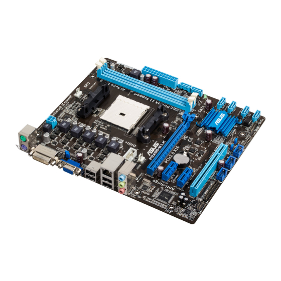
Page 18: Motherboard Layout
1.3.3 Motherboard layout F2A55-M LK Series motherboards include F2A55-M LK PLUS and F2A55-M LK models. The package contents vary from models. The layout illustrations in this user guide are for F2A55-M LK PLUS only. 20.8cm(8.2in) KBMS CPU_FAN DIGI +VRM ATX12V... -
Page 19: Layout Contents
Ensure that you use a APU designed for the FM2 socket. The APU fits in only one correct orientation. DO NOT force the APU into the socket to prevent bending the pins and damaging the APU! F2A55-M LK PLUS F2A55-M LK PLUS APU socket FM2 ASUS F2A55-M LK Series... -
Page 20: Apu Installation
1.4.1 APU installation Chapter 1: Product introduction... -
Page 21: Apu Heatsink And Fan Assembly Installation
1.4.2 APU heatsink and fan assembly installation Apply the Thermal Interface Material to the APU heatsink and APU before you install the heatsink and fan if necessary. To install the APU heatsink and fan assembly ASUS F2A55-M LK Series... - Page 22 To uninstall the APU heatsink and fan assembly Chapter 1: Product introduction 1-10...
-
Page 23: System Memory
DDR2 DIMM socket. DDR3 modules are developed for better performance with less power consumption. The figure illustrates the location of the DDR3 DIMM sockets: Channel Sockets Channel A DIMM_A1 F2A55-M LK PLUS Channel B DIMM_B1 F2A55-M LK PLUS 240-pin DDR3 DIMM sockets ASUS F2A55-M LK Series 1-11... -
Page 24: Memory Configurations
• The maximum 32GB memory capacity can be supported with 16GB or above DIMMs. ASUS will update the memory QVL once the DIMMs are available in the market. • The default memory operation frequency is dependent on its Serial Presence Detect (SPD), which is the standard way of accessing information from a memory module. - Page 25 1.6V • • KINGSTON KHX1866C9D3K4/16GX(XMP) 16GB(4GB x 4) 1.65V • • KINGSTON KHX1866C9D3T1K3/6GX(XMP) 6GB(3 x 2GB) 1.65V • • KINGSTON KHX1866C11D3P1K2/8G 8GB(4GB x 2) 1.5V • • KINGSTON KHX1866C9D3K2/8GX(XMP) 8GB(4GB x 2) 1.65V • • ASUS F2A55-M LK Series 1-13...
- Page 26 DDR3 1600 MHz capability DIMM socket support Chip Vendors Part No. Size Chip NO. Timing Voltage (Optional) Brand 1 DIMM 2 DIMMs 3CCD-1509A A-DATA AM2U16BC2P1 A-DATA • EL1126T 3CCD-1509A A-DATA AM2U16BC4P2 A-DATA • • EL1126T A-DATA AX3U1600GC4G9-2G(XMP) 8GB(2 x 4GB) 9-9-9-24 1.55V-1.75V •...
- Page 27 • Super Talent W1333UB2GS DS SAMSUNG K4B1G0846F • • Super Talent W1333UB4GS DS SAMSUNG K4B2G0846C • • Super Talent W1333UX6GM 6GB(3x 2GB) DS Micron 0BF27D9KPT 9-9-9-24 1.5V • • KINGSTEK KSTD3PC-10600 MICRON PE911-125E • • ASUS F2A55-M LK Series 1-15...
- Page 28 1 DIMM: Supports one module inserted into any slot as Single-channel memory configuration. • 2 DIMMs: Supports two modules inserted into both the blue slots as one pair of Dual- channel memory configuration. Visit the ASUS website at www.asus.com for the latest QVL. Chapter 1: Product introduction 1-16...
-
Page 29: Installing A Dimm
1.5.3 Installing a DIMM To remove a DIMM ASUS F2A55-M LK Series 1-17... -
Page 30: Expansion Slots
Expansion slots In the future, you may need to install expansion cards. The following sub-sections describe the slots and the expansion cards that they support. Unplug the power cord before adding or removing expansion cards. Failure to do so may cause you physical injury and damage motherboard components. -
Page 31: Irq Assignments For This Motherboard
– – – – HD audio shared – – – – – – – SATA controller – – – shared – – – – Onboard USB2.0 controller – – shared – – – – – ASUS F2A55-M LK Series 1-19... -
Page 32: Jumpers
Normal Clear RTC (Default) F2A55-M LK PLUS Clear RTC RAM To erase the RTC RAM: Turn OFF the computer and unplug the power cord. Move the jumper cap from pins 1-2 (default) to pins 2-3. Keep the cap on pins 2-3 for about 5~10 seconds, then move the cap back to pins 1-2. - Page 33 +5VSB F2A55-M LK PLUS (Default) F2A55-M LK PLUS Keyboard power setting USB device wake-up (3-pin USBPW1-4, 3-pin USBPW5-10) Set these jumpers to +5V to wake up the computer from S1 sleep mode (CPU stopped, DRAM refreshed, system running in low power mode) using the connected USB devices.
-
Page 34: Connectors
Connectors 1.8.1 Rear panel ports PS/2 Mouse port (green). This port is for a PS/2 mouse. LAN (RJ-45) port. This port allows Gigabit connection to a Local Area Network (LAN) through a network hub. LAN port LED indications ACT/LINK SPEED Activity/Link LED Speed LED Status... -
Page 35: Internal Connectors
These are not jumpers! DO NOT place jumper caps on the fan connectors. • The CPU_FAN connector supports a CPU fan of maximum 2A (24 W) fan power. • Only the CPU_FAN connector support the ASUS Fan Xpert feature. ASUS F2A55-M LK Series 1-23... - Page 36 The system may become unstable or may not boot up if the power is inadequate. • If you are uncertain about the minimum power supply requirement for your system, refer to the Recommended Power Supply Wattage Calculator at http://support.asus. com/PowerSupplyCalculator/PSCalculator.aspx?SLanguage=en-us for details. Chapter 1: Product introduction 1-24...
- Page 37 SATA3G_2 F2A55-M LK PLUS SATA3G_1 F2A55-M LK PLUS SATA 3.0Gb/s connectors • These connectors are set to AHCI mode by default. If you intend to create a Serial ATA RAID set using these connectors, set the type of the SATA connectors in the BIOS to [RAID].
-
Page 38: System Panel Connector
PIN 1 F2A55-M LK PLUS +HDLED RESET F2A55-M LK PLUS System panel connector • System power LED (2-pin PLED) This 2-pin connector is for the system power LED. Connect the chassis power LED cable to this connector. The system power LED lights up when you turn on the system power, and blinks when the system is in sleep mode. -
Page 39: Digital Audio Connector
F2A55-M LK PLUS HD-audio-compliant Legacy AC’97 pin definition compliant definition F2A55-M LK PLUS Front panel audio connector • We recommend that you connect a high-definition front panel audio module to this connector to avail of the motherboard high-definition audio capability. •... - Page 40 This connector is for a serial (COM) port. Connect the serial port module cable to this connector, then install the module to a slot opening at the back of the system chassis. PIN 1 F2A55-M LK PLUS F2A55-M LK PLUS Serial port (COM) connector The COM module is purchased separately. Chapter 1: Product introduction 1-28...
-
Page 41: Software Support
The contents of the Support DVD are subject to change at any time without notice. Visit the ASUS website at www.asus.com for updates. To run the Support DVD Place the Support DVD into the optical drive. - Page 42 Chapter 1: Product introduction 1-30...
-
Page 43: Chapter 2: Bios Information
BIOS in the future. Copy the original motherboard BIOS using the ASUS Update utility. 2.1.1 ASUS Update utility The ASUS Update is a utility that allows you to manage, save, and update the motherboard BIOS in Windows environment. ®... -
Page 44: Asus Ez Flash 2
Follow the onscreen instructions to complete the updating process. 2.1.2 ASUS EZ Flash 2 The ASUS EZ Flash 2 feature allows you to update the BIOS without using an OS-based utility. Before you start using this utility, download the latest BIOS file from the ASUS website at www.asus.com. -
Page 45: Asus Crashfree Bios 3 Utility
2.1.3 ASUS CrashFree BIOS 3 utility The ASUS CrashFree BIOS 3 is an auto recovery tool that allows you to restore the BIOS file when it fails or gets corrupted during the updating process. You can restore a corrupted BIOS file using the motherboard support DVD or a USB flash drive that contains the updated BIOS file. -
Page 46: Asus Bios Updater
2.1.4 ASUS BIOS Updater The ASUS BIOS Updater allows you to update BIOS in DOS environment. This utility also allows you to copy the current BIOS file that you can use as a backup when the BIOS fails or gets corrupted during the updating process. -
Page 47: Updating The Bios File
At the FreeDOS prompt, type bupdater /pc /g and press <Enter>. D:\>bupdater /pc /g The BIOS Updater screen appears as below. ASUSTek BIOS Updater for DOS V1.30 Current ROM Update ROM BOARD: F2A55-M LK PLUS BOARD: Unknown VER: 0301 VER: Unknown... -
Page 48: Bios Setup Program
BIOS menu screen The BIOS setup program can be used under two modes: EZ Mode and Advanced Mode. You can change modes from the Exit menu or from the Exit/Advanced Mode button in the EZ Mode/Advanced Mode screen. ASUS F2A55-M LK Series... - Page 49 CPU/chassis fan speed the system, or enters the Advanced Mode UEFI BIOS Utility - EZ Mode Exit/Advanced Mode F2A55-M LK PLUS English BIOS Version : 0301 CPU Type : AMD A8-5600K APU with Radeon(tm) HD Graphics Speed : 3300 MHz...
-
Page 50: Advanced Mode
The Advanced Mode provides advanced options for experienced end-users to configure the BIOS settings. The figure below shows an example of the Advanced Mode. Refer to the following sections for the detailed configurations. To access the EZ Mode, click Exit, then select ASUS EZ Mode. Back button Menu items... -
Page 51: Menu Items
Menu items The highlighted item on the menu bar displays the specific items for that menu. For example, selecting Main shows the Main menu items. The other items (Ai Tweaker, Advanced, Monitor, Boot, Tool, and Exit) on the menu bar have their respective menu items. -
Page 52: Main Menu
RAM to clear the BIOS password. See section 1.7 Jumpers for information on how to erase the RTC RAM. The Administrator or User Password items on top of the screen show the default • Not Installed. After you set a password, these items show Installed. 2-10 ASUS F2A55-M LK Series... -
Page 53: Administrator Password
Administrator Password If you have set an administrator password, we recommend that you enter the administrator password for accessing the system. Otherwise, you might be able to see or change only selected fields in the BIOS setup program. To set an administrator password: Select the Administrator Password item and press <Enter>. -
Page 54: Ai Tweaker Menu
F2: Previous Values CPU Power Phase Control Standard F5: Optimized Defaults F10: Save ESC: Exit CPU Voltage Frequency Auto F12: Print Screen CPU Power Duty Control T.Probe Version 2.10.1208. Copyright (C) 2012 American Megatrends, Inc. 2-12 ASUS F2A55-M LK Series... -
Page 55: Ai Overclock Tuner [Auto]
Target CPU Speed : xxxxMHz Displays the current CPU speed. Target DRAM Speed : xxxxMHz Displays the current DRAM speed. 2.4.1 Ai Overclock Tuner [Auto] Allows you to select the CPU overclocking options to achieve the desired CPU internal frequency. Select any of these preset overclocking configuration options: [Auto] Loads the optimal settings for the system. -
Page 56: Gpu Boost [Auto]
CPU permanently, and setting a low voltage may make the system unstable. VDDNB Offset Mode Sign [+] To offset the voltage by a positive value. [–] To offset the voltage by a negative value. 2-14 ASUS F2A55-M LK Series... -
Page 57: Dram Voltage [Auto]
VDDNB Offset Voltage [Auto] Allows you to set the VDDNB Offset voltage. The values range from 0.00625V to 0.500V with a 0.00625V interval. 2.4.10 DRAM Voltage [Auto] Allows you to set the DRAM voltage. The values range from 1.35V to 2.00V with a 0.005V interval. - Page 58 Reducing phase number under light system loading to increase VRM efficiency. [Standard] Proceeds phase control depending on the CPU loading. [Optimized] Loads the ASUS optimized phase tuning profile. [Extreme] Proceeds the full phase mode. [Manual Adjustment] Allows manual adjustment.
-
Page 59: Advanced Menu
Advanced menu The Advanced menu items allow you to change the settings for the CPU and other system devices. Be cautious when changing the settings of the Advanced menu items. Incorrect field values can cause the system to malfunction. EFI BIOS Utility - Advanced Mode Exit Main Ai Tweaker... -
Page 60: Sata Configuration
S.M.A.R.T. (Self-Monitoring, Analysis and Reporting Technology) is a monitor system. When read/write of your hard disk errors occur, this feature allows the hard disk to report warning messages during the POST. Configuration options: [Enabled] [Disabled] 2-18 ASUS F2A55-M LK Series... -
Page 61: Usb Configuration
2.5.3 USB Configuration The items in this menu allow you to change the USB-related features. The USB Devices item shows the auto-detected values. If no USB device is detected, the item shows None. Legacy USB Support [Enabled] [Enabled] Enables the support for USB devices on legacy operating systems (OS). [Disabled] The USB devices can be used only for the BIOS setup program. -
Page 62: Serial Port Configuration
Device Mode [Auto] Allows you to set the Printer port mode. Configuration options: [STD Printer Mode] [SPP Mode] [EPP-1.9 and SPP Mode] [EPP-1.7 and SPP Mode] [ECP Mode] [ECP and EPP-1.9 Mode] [ECP and EPP-1.7 Mode] 2-20 ASUS F2A55-M LK Series... -
Page 63: Apm
2.5.6 Restore AC Power Loss [Power Off] [Power On] The system goes into on state after an AC power loss. [Power Off] The system goes into off state after an AC power loss. [Last State] The system goes into either off or on state, whatever the system state was before the AC power loss. -
Page 64: Network Stack
Ipv6 PXE Support [Enabled] This item appears only when you set the Network Stack item to [Enabled]. When this item is disabled, the IPV6 PXE boot option will not be created. Configuration options: [Disable Link] [Enabled] 2-22 ASUS F2A55-M LK Series... -
Page 65: Monitor Menu
Monitor menu The Monitor menu displays the system temperature/power status, and allows you to change the fan settings. 2.6.1 CPU Temperature / MB Temperature [xxxºC/xxxºF] The onboard hardware monitor automatically detects and displays the CPU and motherboard temperatures. Select Ignore if you do not wish to display the detected temperatures. 2.6.2 CPU / Chassis fan Speed [xxxx RPM] or [Ignore] / [N/A]... -
Page 66: Cpu Voltage, 3.3V Voltage, 5V Voltage, 12V Voltage
The onboard hardware monitor automatically detects the voltage output through the onboard voltage regulators. Select Ignore if you do not want to detect this item. 2.6.5 Anti Surge Support [Enabled] This item allows you to enable or disable the Anti Surge function. Configuration options: [Disabled] [Enabled] 2-24 ASUS F2A55-M LK Series... -
Page 67: Boot Menu
Sets the power-on state of the NumLock to [Off]. 2.7.2 Full Screen Logo [Enabled] [Enabled] Enables the full screen logo display feature. [Disabled] Disables the full screen logo display feature. Set this item to [Enabled] to use the ASUS MyLogo 2™ feature. Chapter 2: BIOS information 2-25... -
Page 68: Fast Boot [Enabled]
[8 sec] [9 sec] [10 sec] 2.7.5 Wait for ‘F1’ If Error [Enabled] When this item is set to [Enabled], the system waits for the F1 key to be pressed when error occurs. Configuration options: [Disabled] [Enabled] 2-26 ASUS F2A55-M LK Series... -
Page 69: Option Rom Messages [Force Bios]
2.7.6 Option ROM Messages [Force BIOS] [Force BIOS] The third-party ROM messages will be forced to display during the boot sequence. [Keep Current] The third-party ROM messages will be displayed only if the third-party manufacturer had set the add-on device to do so. 2.7.7 Next boot after AC Power Loss [Normal Boot] [Normal Boot]... - Page 70 Configuration options: [OK] Forbidden Signature Database Set DBX from File Configuration options: [OK] Get DBX to File Configuration options: [OK] Delete the DBX Configuration options: [Yes] [No] Append an entry to DBX Configuration options: [OK] 2-28 ASUS F2A55-M LK Series...
-
Page 71: Setup Mode [Ez Mode]
• To select the boot device during system startup, press <F8> when ASUS Logo appears. • To access Windows OS in Safe Mode, press <F8> after POST. -
Page 72: Tools Menu
> ASUS O.C. Profile 2.8.1 ASUS EZ Flash 2 Utility Allows you to run ASUS EZ Flash 2. Press [Enter] to launch the ASUS EZ Flash 2 screen. For more details, see section 2.1.2 ASUS EZ Flash 2. 2.8.2 ASUS SPD Information... -
Page 73: Exit Menu
Load Optimized Defaults Save Changes & Reset Discard Changes & Exit ASUS EZ Mode Launch EFI Shell from filesystem device Load Optimized Defaults This option allows you to load the default values for each of the parameters on the Setup menus. - Page 74 2-32 ASUS F2A55-M LK Series...
-
Page 75: Appendices
: (1) cet appareil ne doit pas provoquer d’interférences et (2) cet appareil doit accepter toute interférence, y compris celles susceptibles de provoquer un fonctionnement non souhaité de l’appareil. ASUS F2A55-M LK Series... -
Page 76: Canadian Department Of Communications Statement
ASUS Recycling/Takeback Services ASUS recycling and takeback programs come from our commitment to the highest standards for protecting our environment. We believe in providing solutions for you to be able to responsibly recycle our products, batteries, other components as well as the packaging materials. -
Page 77: Asus Contact Information
+1-812-282-3777 +1-510-608-4555 Web site usa.asus.com Technical Support Telephone +1-812-282-2787 Support fax +1-812-284-0883 Online support support.asus.com ASUS COMPUTER GmbH (Germany and Austria) Address Harkort Str. 21-23, D-40880 Ratingen, Germany +49-2102-959911 Web site www.asus.de Online contact www.asus.de/sales Technical Support Telephone +49-1805-010923* Support Fax... - Page 78 Appendices...