Table of Contents
Advertisement
Advertisement
Table of Contents

Related Manuals for Asus E35M1-M


Summary of Contents for Asus E35M1-M
- Page 1 E35M1-M PRO E35M1-M...
- Page 2 Product warranty or service will not be extended if: (1) the product is repaired, modified or altered, unless such repair, modification of alteration is authorized in writing by ASUS; or (2) the serial number of the product is defaced or missing.
-
Page 3: Table Of Contents
1.5.4 Layout contents ............... 1-6 Central Processing Unit (CPU) ........... 1-7 1.6.1 Installing the CPU fan (for E35M1-M PRO only) ..... 1-7 1.6.2 Uninstalling the CPU fan (for E35M1-M PRO only) ..1-8 System memory ................1-8 Overview ................. 1-8 1.7.1... - Page 4 Managing and updating your BIOS ..........2-1 2.1.1 ASUS Update utility ............2-1 2.1.2 ASUS EZ Flash 2 ............2-2 2.1.3 ASUS CrashFree BIOS 3 utility ........2-3 2.1.4 ASUS BIOS Updater ............2-4 BIOS setup program ..............2-7 Main menu .................. 2-11 2.3.1 System Language ............2-11...
- Page 5 Option ROM Messages ..........2-25 2.7.4 Setup Mode ..............2-26 2.7.5 Boot Option Priorities ............ 2-26 2.7.6 Boot Override ..............2-26 Tools menu ................. 2-27 2.8.1 ASUS EZ Flash Utility ........... 2-27 2.8.2 ASUS Setup Profile ............2-27 Exit menu ..................2-28...
-
Page 6: Notices
Complying with the REACH (Registration, Evaluation, Authorisation, and Restriction of Chemicals) regulatory framework, we published the chemical substances in our products at ASUS REACH website at http://csr.asus.com/english/REACH.htm. DO NOT throw the motherboard in municipal waste. This product has been designed to enable proper reuse of parts and recycling. -
Page 7: Safety Information
Safety information Electrical safety • To prevent electric shock hazard, disconnect the power cable from the electric outlet before relocating the system. • When adding or removing devices to or from the system, ensure that the power cables for the devices are unplugged before the signal cables are connected. If possible, disconnect all power cables from the existing system before you add a device. -
Page 8: Conventions Used In This Guide
Refer to the following sources for additional information and for product and software updates. ASUS websites The ASUS website provides updated information on ASUS hardware and software products. Refer to the ASUS contact information. Optional documentation Your product package may include optional documentation, such as warranty flyers, that may have been added by your dealer. -
Page 9: E35M1-M Series Specifications Summary
Up to 2.5GT/s; UMI Link Memory 2 x DIMM, maximum 8GB, DDR3 1066 MHz, non-ECC, un-buffered memory Single-channel memory architecture Refer to www.asus.com for the latest Memory QVL (Qualified Vendors List). ** When you install a total memory of 4GB capacity or more, Windows 32-bit operating system may only recognize less ®... - Page 10 1 x D-Sub port 1 x eSATA port (6.0Gb/s ready) 1 x LAN (RJ-45) port 4 x USB 2.0/1.1 ports (for E35M1-M PRO) 2 x USB 3.0/2.0 ports (for E35M1-M PRO) 6 x USB 2.0/1.1 ports (for E35M1-M) 1 x Optical S/PDIF out port...
-
Page 11: Chapter 1: Product Introduction
® The motherboard delivers a host of new features and latest technologies, making it another standout in the long line of ASUS quality motherboards! Before you start installing the motherboard, and hardware devices on it, check the items in your package with the list below. - Page 12 The AMD Hudson M1 chipset natively supports the Serial ATA (SATA) ® interface, delivering up to 6.0 Gb/s data transfer. ASUS provides extra SATA 6.0Gb/s ports with enhanced scalability, faster data retrieval, and double the bandwidth of current bus systems.
-
Page 13: Innovative Asus Features
ASUS TurboV Feel the adrenaline rush of real-time OC-now a reality with the ASUS TurboV. This easy OC tool allows you to overclock without exiting or rebooting the OS; and its user-friendly interface makes overclock with just a few clicks away. -
Page 14: Before You Proceed
BIOS file using the bundled support DVD or USB flash disk that contains the latest BIOS file. ASUS EZ Flash 2 ASUS EZ Flash 2 is a utility that allows you to update the BIOS without using an OS-based utility. Before you proceed Take note of the following precautions before you install motherboard components or change any motherboard settings. -
Page 15: Motherboard Overview
Ensure that you unplug the power cord before installing or removing the motherboard. Failure to do so can cause you physical injury and damage motherboard components. ASUS E35M1-M Series motherboards include E35M1-M and E35M1-M PRO two models. The layout varies with models. The layout illustrations in this user guide are for E35M1-M PRO only. -
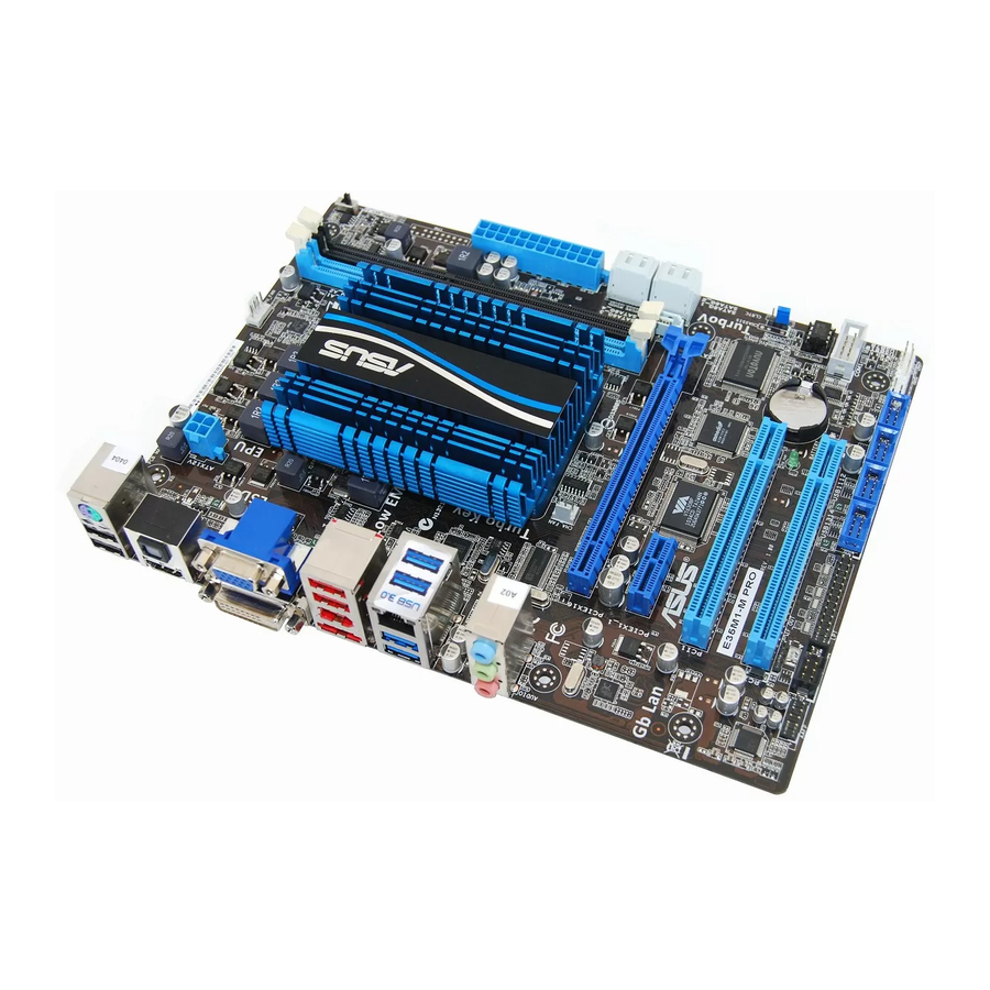
Page 16: Motherboard Layout
Turbo Key II switch 1-22 IEEE 1394a connector (10-1 pin IE1394_1) 1-20 Serial ATA 6.0Gb/s connectors (7-pin 1-18 Front panel audio connector (10-1 pin AAFP) 1-17 SATA6G_1~5) Clear RTC RAM (3-pin CLRTC) 1-13 Digital audio connector (4-1 pin SPDIF_OUT) 1-18 ASUS E35M1-M Series... -
Page 17: Central Processing Unit (Cpu)
Integrated dual-core AMD® Zacate™ 18W processor E35M1-M PRO E35M1-M PRO AMD Zacate™ 18W processor 1.6.1 Installing the CPU fan (for E35M1-M PRO only) To install the CPU fan: Place the CPU fan on top of the CPU heatsink. Secure the fan on the heatsink with the four screws. -
Page 18: Uninstalling The Cpu Fan (For E35M1-M Pro Only)
1.6.2 Uninstalling the CPU fan (for E35M1-M PRO only) To uninstall the CPU fan: Disconnect the CPU fan cable from the connector on the motherboard. Remove the four screws from the CPU fan. Remove the CPU fan from the CPU heatsink. -
Page 19: Memory Configurations
2.4 Ai Tweaker menu for manual memory frequency adjustment. • For system stability, use a more efficient memory cooling system to support a full memory load (2 DIMMs) or overclocking condition. E35M1-M Series Motherboard Qualified Vendors Lists (QVL) DDR3-1333 MHz capability DIMM socket... - Page 20 Super Talent W1333UB2GS DS Samsung K4B1G0846F • Super Talent W1333UB4GS DS Samsung K4B2G0846C • Super Talent W1333UX6GM 6GB(3x2GB) DS Micron 0BF27D9KPT 9-9-9-24 1.5V • The memory modules with 1333MHz capability run at 1066MHz on this motherboard. 1-10 ASUS E35M1-M Series...
- Page 21 Micron 9BF27D9KPV 7-7-7-20 1.65V • SS: Single-sided / DS: Double-sided DIMM support: • A*: Supports one module inserted into any slot as single-channel memory configuration. Visit the ASUS website at www.asus.com for the latest QVL. Chapter 1: Product introduction 1-11...
-
Page 22: Expansion Slots
This motherboard has a PCI Express 2.0 x1 slot that supports PCI Express x1 2.0 graphic cards complying with the PCI Express specifications. 1.8.5 PCI Express x16 slot This motherboard has a PCI Express 2.0 x16 slot that supports PCI Express x16 2.0 graphic cards complying with the PCI Express specifications. 1-12 ASUS E35M1-M Series... -
Page 23: Jumpers
Clear RTC (Default) E35M1-M PRO E35M1-M PRO Clear RTC RAM To erase the RTC RAM: 1. Turn OFF the computer and unplug the power cord. 2. Move the jumper cap from pins 1-2 (default) to pins 2-3. Keep the cap on pins 2-3 for about 5-10 seconds, then move the cap back to pins 1-2. -
Page 24: Connectors
6-channel, and 8-channel configurations, the function of this port becomes Front Speaker Out. Microphone port (pink). This port connects a microphone. Refer to the audio configuration table on the next page for the function of the audio ports in the 2, 4, 6, or 8-channel configuration. 1-14 ASUS E35M1-M Series... - Page 25 Use a chassis with HD audio module in the front panel to support an 8-channel audio output. USB 3.0 ports 1 and 2 (for E35M1-M PRO only) . These two 9-pin Universal Serial Bus (USB) ports are for USB 3.0/2.0 devices.
-
Page 26: Internal Connectors
The system may become unstable or may not boot up if the power is inadequate. • If you are uncertain about the minimum power supply requirement for your system, refer to the Recommended Power Supply Wattage Calculator at http://support.asus. com/PowerSupplyCalculator/PSCalculator.aspx?SLanguage=en-us for details. 1-16... - Page 27 E35M1-M PRO pin definition compliant definition E35M1-M PRO Front panel audio connector • We recommend that you connect a high-definition front panel audio module to this connector to avail of the motherboard’s high-definition audio capability. • If you want to connect a high-definition front panel audio module to this connector, set the Front Panel Type item in the BIOS setup to [HD].
- Page 28 S/PDIF Out module cable to this connector, then install the module to a slot opening at the back of the system chassis. SPDIF_OUT E35M1-M PRO E35M1-M PRO Digital audio connector The S/PDIF module is purchased separately. 1-18 ASUS E35M1-M Series...
-
Page 29: System Panel Connector
PWRSW RESET E35M1-M PRO * Requires an ATX power supply E35M1-M PRO System panel connector • System power LED (2-pin PLED) This 2-pin connector is for the system power LED. Connect the chassis power LED cable to this connector. The system power LED lights up when you turn on the system power, and blinks when the system is in sleep mode. - Page 30 PIN 1 PIN 1 PIN 1 PIN 1 E35M1-M PRO E35M1-M PRO USB2.0 connectors Never connect a 1394 cable to the USB connector. Doing so will damage the motherboard! The USB module cable is purchased separately. 1-20 ASUS E35M1-M Series...
- Page 31 The serial port bracket (COM1) is purchased separately. COM1 PIN 1 E35M1-M PRO E35M1-M PRO Serial port (COM1) connector Chapter 1: Product introduction 1-21...
-
Page 32: Onboard Switches
E35M1-M PRO E35M1-M PRO Turbo Key II switch • The O2LED2 LED near the Turbo Key II switch lights when the switch setting is turned to Enable. Refer to section 1.12 Onboard LEDs for the exact location of the O2LED2 LED. -
Page 33: Onboard Leds
Powered Off E35M1-M PRO Onboard LED Turbo Key II LED The Turbo Key II LED lights when the Turbo Key II switch is turned to Enable. O2LED2 E35M1-M PRO E35M1-M PRO Turbo Key II LED Chapter 1: Product introduction 1-23... -
Page 34: Software Support
The contents of the Support DVD are subject to change at any time without notice. Visit the ASUS website at www.asus.com for updates. To run the Support DVD Place the Support DVD to the optical drive. -
Page 35: Chapter 2: Bios Information
BIOS in the future. Copy the original motherboard BIOS using the ASUS Update utility. 2.1.1 ASUS Update utility The ASUS Update is a utility that allows you to manage, save, and update the motherboard BIOS in Windows environment. ®... -
Page 36: Asus Ez Flash 2
Follow the onscreen instructions to complete the updating process. 2.1.2 ASUS EZ Flash 2 The ASUS EZ Flash 2 feature allows you to update the BIOS without using an OS-based utility. Before you start using this utility, download the latest BIOS file from the ASUS website at www.asus.com. -
Page 37: Asus Crashfree Bios 3 Utility
2.1.3 ASUS CrashFree BIOS 3 utility The ASUS CrashFree BIOS 3 is an auto recovery tool that allows you to restore the BIOS file when it fails or gets corrupted during the updating process. You can restore a corrupted BIOS file using the motherboard support DVD or a USB flash drive that contains the updated BIOS file. -
Page 38: Asus Bios Updater
2.1.4 ASUS BIOS Updater The ASUS BIOS Updater allows you to update BIOS in DOS environment. This utility also allows you to copy the current BIOS file that you can use as a backup when the BIOS fails or gets corrupted during the updating process. - Page 39 The BIOS Updater backup screen appears indicating the BIOS backup process. When BIOS backup is done, press any key to return to the DOS prompt. ASUSTek BIOS Updater for DOS V1.18 Current ROM Update ROM BOARD: E35M1-M PRO BOARD: Unknown VER: 0027 VER:...
-
Page 40: Updating The Bios File
Select the Load Optimized Defaults item under the Exit menu. Refer to section 2.9 Exit menu for details. • Ensure to connect all SATA hard disk drives after updating the BIOS file if you have disconnected them. ASUS E35M1-M Series... -
Page 41: Bios Setup Program
• The BIOS setup screens shown in this section are for reference purposes only, and may not exactly match what you see on your screen. • Visit the ASUS website at www.asus.com to download the latest BIOS file for this motherboard. -
Page 42: Bios Menu Screen
Selects the boot device priority • The boot device options vary depending on the devices you installed to the system. • The Boot Menu(F8) button is available only when the boot device is installed to the system. ASUS E35M1-M Series... -
Page 43: Advanced Mode
The Advanced Mode provides advanced options for experienced end-users to configure the BIOS settings. The figure below shows an example of the Advanced Mode. Refer to the following sections for the detailed configurations. To access the EZ Mode, click Exit, then select ASUS EZ Mode. Back button Menu items... -
Page 44: Scroll Bar
You cannot select an item that is not user-configurable. A configurable field is highlighted when selected. To change the value of a field, select it and press <Enter> to display a list of options. 2-10 ASUS E35M1-M Series... -
Page 45: Main Menu
Main menu The Main menu screen appears when you enter the Advanced Mode of the BIOS Setup program. The Main menu provides you an overview of the basic system information, and allows you to set the system date, time, language, and security settings. EFI BIOS Utility - Advanced Mode Exit Main... -
Page 46: Administrator Password
To clear the user password, follow the same steps as in changing a user password, but press <Enter> when prompted to create/confirm the password. After you clear the password, the User Password item on top of the screen shows Not Installed. 2-12 ASUS E35M1-M Series... -
Page 47: Ai Tweaker Menu
Ai Tweaker menu The Ai Tweaker menu items allow you to configure overclocking-related items. Be cautious when changing the settings of the Ai Tweaker menu items. Incorrect field values can cause the system to malfunction. The configuration options for this section vary depending on the CPU and DIMM model you installed on the motherboard. -
Page 48: Ai Overclock Tuner
<-> keys to adjust the value. To restore the default setting, type [auto] using the keyboard and press <Enter>. Changing the values in this menu may cause the system to become unstable! If this happens, revert to the default settings. 2-14 ASUS E35M1-M Series... -
Page 49: Cpu Offset Mode Sign
2.4.6 CPU Offset Mode Sign [+] To offset the voltage by a positive value. [–] To offset the voltage by a negative value. CPU Voltage [Auto] Allows you to set the CPU Offset voltage. The values range from -0.3V to +0.5V with a 0.00625V interval. -
Page 50: Load-Line Calibration
The items shown in submenu may be different due to the CPU you installed. Limit CPUID Maximum [Disabled] [Enabled] Allows legacy operating systems to boot even without support for CPUs with extended CPUID functions. [Disabled] Disables this function. 2-16 ASUS E35M1-M Series... -
Page 51: Sata Configuration
Cool ‘n’ Quiet [Enabled] Enables or disables the AMD Cool ‘n’ Quiet technology. Configuration options: [Enabled] ® [Disabled] NX Mode [Enabled] Enables or disables no-execute page protection function. Configuration options: [Disabled] [Enabled] SVM Mode [Enabled] Enables or disables CPU virtualization. Configuration options: [Disabled] [Enabled] C6 Mode [Enabled] Enables or disables C6 mode. -
Page 52: Usb Configuration
This item is user-configurable only when the IGFX Multi-Monitor item is set to [Disabled] and allows you to set the default video output device. Configuration options: [IGFX Video] [PCIE Video] Integrated Graphics [Auto] Enables or disables the integrated graphics. Configuration options: [Auto] [Force] 2-18 ASUS E35M1-M Series... -
Page 53: Onboard Devices Configuration
This item appears only when you set the previous item to [Enabled] and allows you to enable or disable the PXE OptionRom of the Realtek LAN controller. Configuration options: [Enabled] [Disabled] The following two items only appears on E35M1-M PRO. Asmedia USB 3.0 Controller [Enabled] This item only appears on E35M1-M PRO. -
Page 54: Apm
Power On By PS/2 Mouse [Disabled] [Disabled] Disables the Power On by a PS/2 mouse. [Enabled] Enables the Power On by a PS/2 mouse. This feature requires an ATX power supply that provides at least 1A on the +5VSB lead. 2-20 ASUS E35M1-M Series... - Page 55 Power On By PME [Disabled] [Disabled] Disables PME wake from sleep states. [Enabled] Enables PME wake from sleep states. Power On By Ring [Disabled] [Disabled] Disables Ring to generate a wake event. [Enabled] Enables Ring to generate a wake event. Power On By RTC [Disabled] [Disabled] Disables RTC to generate a wake event.
-
Page 56: Monitor Menu
The onboard hardware monitor automatically detects and displays the CPU and chassis fan speeds in rotations per minute (RPM). If the fan is not connected to the motherboard, the field shows N/A. Select Ignore if you do not wish to display the detected speed. 2-22 ASUS E35M1-M Series... -
Page 57: Cpu Q-Fan Control
2.6.3 CPU Q-Fan Control [Enabled] [Disabled] Disables the CPU Q-Fan control feature. [Enabled] Enables the CPU Q-Fan control feature. CPU FAN Mode [DC Mode] This item appears only when you enable the CPU Q-Fan Control feature and allows you to select the CPU fan mode. -
Page 58: Chassis Q-Fan Control
The onboard hardware monitor automatically detects the voltage output through the onboard voltage regulators. Select Ignore if you do not want to detect this item. 2.6.6 Anti Surge Support [Disabled] This item allows you to enable or disable the Anti Surge function. Configuration options: [Disabled] [Enabled] 2-24 ASUS E35M1-M Series... -
Page 59: Boot Menu
[Enabled] Enables the full screen logo display feature. [Disabled] Disables the full screen logo display feature. Set this item to [Enabled] to use the ASUS MyLogo 2™ feature. 2.7.3 Option ROM Messages [Force BIOS] [Force BIOS] The third-party ROM messages will be forced to display during the boot sequence. -
Page 60: Setup Mode
• To select the boot device during system startup, press <F8> when ASUS Logo appears. • To access Windows OS in Safe Mode, do any of the following: - Press <F5>... -
Page 61: Tools Menu
> ASUS EZ Flash Utility > ASUS Setup Profile 2.8.1 ASUS EZ Flash Utility Allows you to run ASUS EZ Flash 2. When you press <Enter>, ASUS EZ Flash 2 screen appears. For more details, refer to section 2.1.2 ASUS EZ Flash 2. 2.8.2 ASUS Setup Profile This item allows you to store or load multiple BIOS settings. -
Page 62: Exit Menu
This option allows you to enter the EZ Mode screen. Launch EFI Shell from filesystem device This option allows you to attempt to launch the EFI Shell application (shellx64.efi) from one of the available filesystem devices. 2-28 ASUS E35M1-M Series... -
Page 63: Asus Contact Information
+1-510-739-3777 +1-510-608-4555 Web site usa.asus.com Technical Support Telephone +1-812-282-2787 Support fax +1-812-284-0883 Online support support.asus.com ASUS COMPUTER GmbH (Germany and Austria) Address Harkort Str. 21-23, D-40880 Ratingen, Germany +49-2102-959911 Web site www.asus.de Online contact www.asus.de/sales Technical Support Telephone (Component) +49-1805-010923*...
Need help?
Do you have a question about the E35M1-M and is the answer not in the manual?
Questions and answers