Table of Contents
Advertisement
Advertisement
Table of Contents

Related Manuals for Yamaha KAX-2500


Summary of Contents for Yamaha KAX-2500
- Page 1 POWER AMPLIFIER 使用说明书 Owner’s Manual...
-
Page 2: Explanation Of Graphical Symbols
• Explanation of Graphical Symbols The lightning flash with arrowhead symbol within an equilateral triangle is intended to CAUTI ON alert the user to the presence of uninsulated RISK OF ELECTRIC SHOCK “dangerous voltage” within the product’s DO NOT OPEN enclosure that may be of sufficient magnitude to constitute a risk of electric shock to persons. - Page 3 Precautions — For safe operation — WARNING Do not modify the unit. Doing so is a fire and electrical shock haz- ● Installation ard. If lightning begins to occur, turn off the power switch of the unit as ● Connect this unit’s power cord only to an AC outlet of the type ●...
- Page 4 1. IMPORTANT NOTICE: DO NOT MODIFY THIS UNIT! This product, when installed as indicated in the instructions contained in this manual, meets FCC requirements. Modifications not expressly approved by Yamaha may void your authority, granted by the FCC, to use the product. 2. IMPORTANT: When connecting this product to accessories and/or another product use only high quality shielded cables.
-
Page 5: Table Of Contents
Introduction Thank you for your purchase of the YAMAHA KAX-5000, KAX3500 or KAX-2500 power amplifier. These KAX-series amplifiers fully incorporate Yamaha’s renown technological expertise, and offer high reliability, rock-solid stability, and superb acoustic characteristics—all in a trim, 2U-sized pack- age. -
Page 6: Controls And Functions
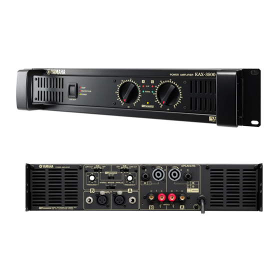
Controls and Functions ■ Front Panel 1 POWER switch and indicator How to install the security cover (1) Use the supplied hex wrench to remove the four attach- Press to toggle the power on or off. The POWER indicator ment screws from the amplifier. lights up green when the power is ON. -
Page 7: Rear Panel
■ Rear Panel SPEAKERS LOW CUT WOOFER LOW CUT WOOFER STEREO BRIDGE PARALLEL FREQUENCY FREQUENCY INPUT BRIDGE 1 FILTER switch and FREQUENCY adjustment knob ON/OFF switch (One pair for each channel) If you set this switch ON, the amplifier adds low-frequency Use these controls to select the filter type and adjust the cutoff compensation so as to enhance speaker output. -
Page 8: Speaker Jacks
4 STEREO/PARALLEL/BRIDGE switch Use this switch to select the operating mode. • STEREO mode Channels A and B operate independently (as with a conven- tional stereo amplifier). The Channel A input goes to the Chan- nel A output jacks, and the Channel B input goes to the Channel B output jacks. -
Page 9: Speaker Connections
Speaker Connections ■ Speaker impedance Speakers can be connected to the amplifier as shown below. Note that speaker impedance will vary according to the connection method and the ’ number of speakers. Please be sure that your speakers impedance is not less than the relevant minimum value indicated below. Connection configurations for STEREO and Connection configurations for BRIDGE PARALLEL modes... -
Page 10: Wiring
■ Wiring 5-way binding post Speakon connector (1) Turn off the POWER switch. (1) Turn off the POWER switch. (2) Remove the cover attachment screws and remove the pro- (2) Insert the Neutrik NL4FC plugs into the Speakon connec- tective cover from the speaker terminals. tor on the rear of the amplifier, and turn clockwise to lock. -
Page 11: Rack Mounting
Rack Mounting Mounting in a standard EIA rack If you are mounting multiple power amplifiers in a rack, be sure to install ventilation panel(s) as shown below. Also be sure to use metal brack- ets (one on each side) to support the rear of each amplifer. Note: EIA stands for Electronic Industries Alliance. -
Page 12: Specifications
Specifications and descriptions in this owner’s manual are for information purposes only. Yamaha Corp. reserves the right to change or modify products or spec- ifications at any time without prior notice. Since specifications, equipment or options may not be the same in every locale, please check with your Yamaha dealer. -
Page 13: Block Diagram
■ Block Diagram KAX-5000 KAX-3500, KAX-2500 CHANNEL A Ach Power Amp SPEAKERS State variable Limiter Active filter Frequency [25 Hz-150 Hz] CHANNEL A [BRIDGE] SIGNAL [PARALLEL] CHANNEL A YAMAHA CLIP SPEAKER PROCESSING Temperature PROTECTION Sensor Protection INPUT (Heat Sink) Circuit... -
Page 14: Dimensions
■ Dimensions Unit: mm ■ Current Draw KAX-5000 Line Current (A) Power (W) Thermal Dissipation 100/120V 230/240V Dissipated Btu/h kcal/h standby 0.08 0.04 idle 8Ω/ch 1/8 power 4Ω/ch 8Ω/ch 1100 1/3 power 4Ω/ch 14.7 1057 1900 KAX-3500 Line Current (A) Power (W) Thermal Dissipation 100/120V... -
Page 15: Troubleshooting
KAX-5000: 11A (100V), 13A (120V), 25A (240V) KAX-3500: 71A (100V), 87A (120V), 66A (240V) KAX-2500: 103A (100V), 150A (120V), 68A (240V) Troubleshooting The following table lists the main causes of abnormal operation and the corrective measures required, as well as the protective circuit opera- tion in each case. - Page 16 For details of products, please contact your nearest Yamaha 关于各产品的详细信息,请向就近的 YAMAHA 代理商或下列 representative or the authorized distributor listed below. 经销商询问。 MARTA NORTH AMERICA ASIA Olimpus Music Ltd. CANADA THE PEOPLE’S REPUBLIC OF CHINA The Emporium, Level 3, St. Louis Street Msida Yamaha Canada Music Ltd.
Need help?
Do you have a question about the KAX-2500 and is the answer not in the manual?
Questions and answers