Table of Contents
Advertisement
Quick Links
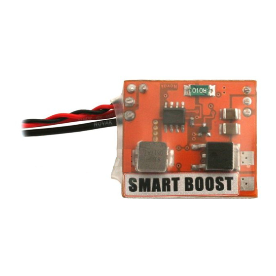
SMART-BOOST 1-CELL Li-Po STEP-UP MODULE
#55-5474-1
Input Voltage ........................................................ 1S Li-Po
Output Voltage ........................................................6 Volts
Output Current
Output Current
Power Wire Size ............................................. 20G Silicone
Input Wire Gauge .................................................20 AWG
Weight ............................................. 0.48 oz. / 13.5 grams
Size ...........1.18" x 1.04" x 0.45" / 30.0 x 26.5 x 11.5 mm
LEDs ................................................................. 2 on-board
SMART
BOOST
Step Up Your Voltage!
Novak's Smart Boost 1-Cell Li-Po Step-Up Module allows nearly any brushless or brushed
speed control, receiver and servo to run on 1-cell Li-Po. This new technology expands racing
opportunities for many drivers by reducing racing expenses and track sizes.
To benefit from all of the technical features of the Smart Boost,
PLEASE READ ALL INSTRUCTIONS BEFORE OPERATION
INSTALLATION
(refer to Fig. 1 on back)
1. MOUNT SMART BOOST
Find a suitable installation point in the vehicle,
preferably close to the ESC and receiver so the
included receiver harness will easily reach it.
A. If mounting in a nitro vehicle, install the Smart
Boost near the receiver battery pack to ensure the
input harness will reach the vehicle's receiver. For
nitro installation, go to Step 2A.
2. PREPARE WIRES FOR INSTALLATION
The Smart Boost's red and black 20G-silicone
power wires connect to the ESC's battery
power wires
(where the ESC's main-battery wires
.
Cut the wires to proper
connect to the ESC's PCB)
length and strip 3/16"–1/4" of insulation off
the ends and tin with solder.
A. In a nitro vehicle, cut the input wires to proper
length to reach the receiver battery pack, and
strip and tin as instructed in Step 2. For nitro
installation, go to Step 3A.
3. SOLDER POWER WIRES
Solder the stripped and tinned ends of the
Smart Boost's power wires to the ESC's main
battery pack input or solder tabs.
A. In a nitro vehicle, connect the Smart Boost's red
and black power wires to the corresponding red and
black wires of a matching connector on the receiver
pack (red to red & black to black). This allows you to
plug the Smart Boost into your receiver battery pack.
4. PLUG INTO RECEIVER
Plug the Smart Boost's receiver harness into
a spare slot in the receiver. Zip tie or coil any
extra harness wire.
3-2009
SPECIFICATIONS
....................................... 3 Amps
(constant)
........................................... 5 Amps
(surge)
OPERATION
1. SMART BOOST SETUP
No setup is necessary for the module.
2. POWER UP SMART BOOST
To turn the vehicle's power on, simply turn
the Smart Boost's switch ON. It is important
to leave the ESC's original switch in the OFF
position while running the system.
NOTE: With some Novak ESCs that include built-in
servo voltage protection, it may be necessary to switch
ON, then after a moment, switch OFF the ESC's switch
for proper operation.
3. POWER DOWN SMART BOOST
When finished running the vehicle, simply turn
OFF the Smart Boost's switch.
4. LOW BATTERY WARNING
When the Smart Boost "blips" the vehicle's
ESC throttle and servo power, it is advised to
immediately cease running the vehicle and
recharge the battery.
Novak Electronics, Inc.
17032 Armstrong Avenue
Irvine, CA 92614
(949) 833-8873 • FAX (949) 833-1631
Customer Service e-mail: cs@teamnovak.com
Monday-Friday: 8:00am-5:00pm (PST)
w w w . t e a m n o v a k . c o m
Advertisement
Table of Contents

Related Manuals for NOVAK SMART-BOOST - BASIC SETUP GUIDE 3-2009


Summary of Contents for NOVAK SMART-BOOST - BASIC SETUP GUIDE 3-2009
- Page 1 Step Up Your Voltage! Step Up Your Voltage! Novak’s Smart Boost 1-Cell Li-Po Step-Up Module allows nearly any brushless or brushed Novak’s Smart Boost 1-Cell Li-Po Step-Up Module allows nearly any brushless or brushed speed control, receiver and servo to run on 1-cell Li-Po. This new technology expands racing speed control, receiver and servo to run on 1-cell Li-Po.
- Page 2 PC board, or any damage caused by a crash, flooding or natural disaster. that requires servicing. that requires servicing. Because Novak has no control over the connection & use of the module, Because Novak has no control over the connection & use of the module, WARRANTY SERVICE:...
Need help?
Do you have a question about the SMART-BOOST - BASIC SETUP GUIDE 3-2009 and is the answer not in the manual?
Questions and answers