Advertisement
Advertisement
Table of Contents

Subscribe to Our Youtube Channel
Related Manuals for Fishman POWERCHIP


Summary of Contents for Fishman POWERCHIP
- Page 1 USER GUIDE POWERCHIP...
-
Page 2: Troubleshooting
Welcome Thank you for making Fishman a part of your acoustic experience. We are proud to offer you the fi nest acoustic amplifi cation products available: high-quality professional-grade tools which empower you to sound your very best. Troubleshooting If you are unfamiliar with this product, please pay close attention to the require- ments for installation. -
Page 3: Mono Operation
Electric Guitar Equipped with Plug a standard mono instrument cable into the Fishman Powerbridge and Powerchip output of the Powerchip equipped guitar and combine the magnetic and piezo signals into a single buffered composite, suitable for any available instrument level audio input. -
Page 4: Stereo Operation
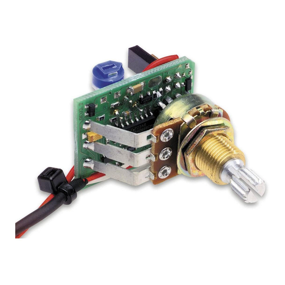
Electric Guitar Equipped with Plug a stereo “Y” cable into the output of Fishman Powerbridge and Powerchip the Powerchip equipped guitar and split the magnetic and piezo pickup signals to separate destinations. Send the buffered piezo signal (Ring) to any instrument level audio input, such as an acoustic instrument amplifi... - Page 5 Piezo Trim and Phase Adjust the small rotary trim pot on the backside of the Powerchip to match piezo and magnetic pickup levels. Move the Phase jumper on the backside of the Powerchip to eliminate phase cancellation between the piezo and magnetic pickups.
-
Page 6: Prepare The Instrument
Prepare the Instrument Telecaster style guitars File or sand down the corners of the 9-pin jack to fi t the standard Telecaster mounting hole. Stratocaster style guitars You will need to drill out the back wall of the jack cavity to accom- modate the supplied 9-pin jack. -
Page 7: Installation And Connections
Installation and Connections Warning: The solder pad terminals and the adjacent components on the Powerchip circuit board are quite fragile and can be easily overheated. Use only a low wattage soldering iron (30 watts max) to make your wire connections. To best utilize the space inside the guitar, solder the wires to the circuit board so that they exit toward the volume pot terminals. - Page 8 Note: If you install the Powerchip Output (Tip) with active magnetic pickups (such...
- Page 9 4. Solder the 9-pin jack to the system. A prewired output cable from the Powerchip is to be soldered to the provided 9-pin jack. Prepare the jack by soldering a jumper wire between the sleeve terminal, located on the business end of the jack, and terminal #2, directly below.
-
Page 10: Optional Accessories
Optional Accessories • Piezo-Magnetic Pickup Selector Switch—a three position switch for selecting between piezo and magnetic pickup combinations. • Battery Compartment—a fl ush mounted, pivoting compartment allows easy access and quick battery changes. -
Page 11: Specifications
Specifi cations Battery Life: 200 Hours Current Draw: Less than 2.8mA Frequency Range: 20–20,000 Hz Trim Control Range: 18dB Maximum Output Voltage: 15V peak to peak... - Page 12 WWW.FISHMAN.COM 009-074-001 Rev D 4-09...
Need help?
Do you have a question about the POWERCHIP and is the answer not in the manual?
Questions and answers