
Related Manuals for TELEDYNE FLIR M364C


Summary of Contents for TELEDYNE FLIR M364C
- Page 1 M300 SERIES INSTALLATION & OPERATION INSTRUCTIONS English (en-US) Date: 08-2024 Document number: 71004 (Rev 7) © 2024 Teledyne FLIR LLC...
- Page 3 Trademark and patents notice FLIR, Instalert, Infrared Everywhere, The World’s Sixth Sense and ClearCruise are registered or claimed trademarks of Teledyne FLIR LLC. All other trademarks, trade names, or company names referenced herein are used for identification only and are the property of their respective owners.
-
Page 5: Table Of Contents
..........27 Technical accuracy ........... 12 M300 Series ............... 27 Publication copyright ..........13 M300 Series with optional mounting riser ..27 CHAPTER 2 DOCUMENT INFORMATION....14 Mounting riser ............28 Document information ..........15 CHAPTER 6 LOCATION REQUIREMENTS ....29 Applicable products ........... - Page 6 CHAPTER 7 MOUNTING..........33 NMEA 0183 overview 10.1 ..........50 NMEA 0183 connection Tools required 10.2 ......... 51 ............. 34 Enabling NMEA features Camera orientation 10.3 ........51 ............ 34 Ball-down (upside down) mounting: rotating CHAPTER 11 NETWORK CONNECTIONS....52 the front cover Network connections ............
- Page 7 Power connection Camera settings menus 12.1 ............ 62 14.7 ......... 81 Camera settings 14.8 ............81 Inline fuse and thermal breaker ratings ....62 System settings 14.9 ............86 Power distribution ............. 62 Troubleshooting 14.10 ............. 86 Power cable drain wire connection ......
- Page 8 Cleaning the camera 19.3 ..........102 CHAPTER 20 SYSTEM CHECKS AND TROUBLESHOOTING ..........103 Thermal camera troubleshooting 20.1 ....... 104 Teledyne FLIR Maritime product support and 20.2 servicing ................105 CHAPTER 21 TECHNICAL SPECIFICATION.... 106 Physical specification 21.1 ........... 107 Power specification 21.2...
-
Page 9: Chapter 1: Important Information
CHAPTER 1: IMPORTANT Warning: Ensure safe navigation INFORMATION This product is intended only as an aid to navigation and must never be used in preference to sound navigational judgment. Only official government charts and notices to mariners contain all the current information needed for safe Safety warnings navigation, and the captain is responsible for their prudent use. -
Page 10: Regulatory Notices
Warning: PoE isolation coupler Caution: Do not open the unit Some networks require an inline Power over Ethernet (PoE) The unit is factory sealed to protect against atmospheric isolation coupler to be fitted before the camera can be humidity, suspended particulates and other contaminates. connected to the network. -
Page 11: Inspecting The Thermal Camera
EMC installation guidelines • Rinse the lens with fresh water to remove all dirt particles and salt deposits, and allow to dry naturally. FLIR equipment and accessories conform to the appropriate Electromagnetic • If any spots or smears remain, very gently wipe the lens window with Compatibility (EMC) regulations, to minimize electromagnetic interference a clean microfibre cloth or soft cotton cloth. -
Page 12: Connections To Other Equipment
It is important that you register your product to receive full warranty benefits. Teledyne FLIR LLC declares that the following products are in compliance Your unit package includes a bar code label indicating the serial number of with the EMC Directive 2014/30/EU: the unit. -
Page 13: Publication Copyright
Publication copyright Copyright © 2023 Teledyne FLIR LLC. All rights reserved. No parts of this material may be copied, translated, or transmitted (in any medium) without the prior written permission of Teledyne FLIR LLC. -
Page 14: Chapter 2: Document Information
CHAPTER 2: DOCUMENT INFORMATION CHAPTER CONTENTS • 2.1 Document information — page 15 • 2.2 Applicable products — page 15 • 2.3 Additional system components — page 16 • 2.4 Product documentation — page 16 • 2.5 Operation instructions — page 16 •... -
Page 15: Document Information
2.1 Document information Camera (Single Payload) Description M332 (9 Hz) — (E70528) • 24° Field of View (FOV) This document contains important information related to the installation • 320px thermal sensor resolution and operation of your FLIR product. The document includes information to help you: M332 (30 Hz) —... -
Page 16: Additional System Components
2.3 Additional system components 2.5 Operation instructions M300 Series thermal cameras can be used in conjunction with the following For detailed operation instructions for your product, refer to the optional items, available separately from FLIR: documentation that accompanies your display. -
Page 17: Chapter 3: Product And System Overview
CHAPTER 3: PRODUCT AND SYSTEM OVERVIEW CHAPTER CONTENTS • 3.1 Product overview — page 18 • 3.2 System overview — page 19 • 3.3 Control options — page 21 • 3.4 Display options — page 21 • 3.5 Multicasting — page 22 •... -
Page 18: Product Overview
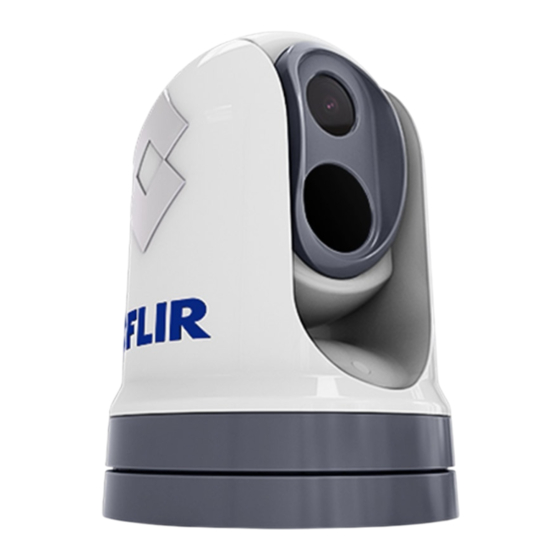
• 12 V or 24 V dc power. M300 (dual payload) The M300 Series dual payload variant is a maritime camera equipped with a visible and thermal imaging system, for use on nearly any kind of vessel. Dual payload cameras have 2 separate imaging cores: •... -
Page 19: System Overview
For an overview of the camera’s video connection options, refer to: p.44 — Video connections 4. Pan assembly. The M300 Series system has the following key functions and features: • IP connectivity to simplify installation and system integration. • 6 simultaneous video outputs, including 2 visible and 2 thermal digital streams. - Page 20 Power connections are not shown in this illustration. The camera, display and Ethernet network switch require their own dedicated power connections. The JCU-2 is powered via Power over Ethernet (PoE), using an optional PoE injector. Item Description M300 Series camera Digital video (HD-SDI) monitor, available separately from third-party retailers...
-
Page 21: Control Options
3.3 Control options 3.4 Display options The following illustration shows the different options available for controlling The following illustration shows the different options available for displaying the camera. the camera’s digital and analog video feeds. These options are not exclusive; the camera can be controlled from more All video feeds are available simultaneously. -
Page 22: Multicasting
3. Digital video monitor: via a HD-SDI connection directly to the camera (or identically, and certain devices in a network may not necessarily support a HDMI connection via a converter, available separately from third-party multicasting. retailers). 4. Analog video monitor: via a composite analog video connection 3.6 Enabling multicasting available on the camera’s power cable. -
Page 23: Compatible Multifunction Displays
3.8 Compatible multifunction displays Some multifunction displays (MFDs) may support camera control options via an ONVIF (Profile S) compatible video / camera application. The range of control options available will be dependent on the support that the MFD manufacturer has developed for the dedicated video / camera application. Refer to your MFD manufacturer for information on whether your display is compatible with the camera. -
Page 24: Chapter 4: Parts Supplied
CHAPTER 4: PARTS SUPPLIED CHAPTER CONTENTS • 4.1 Parts supplied — page 25... -
Page 25: Parts Supplied
4.1 Parts supplied Item Description Right-angled RayNet (Ethernet) to RayNet (Ethernet) cable 3 m (9.8 ft.) Right-angled HD-SDI video cable (with BNC connectors) 3 m (9.8 ft.) Right-angled power/NMEA 0183/video cable 3 m (9.8 ft.) Mounting riser (1) Fixings: 3x M6 threaded studs, 2x M6 flat nuts, 3x M6 dome nuts, 3x M6 flat washers and 3x M6 nyloc nuts. -
Page 26: Chapter 5: Product Dimensions
CHAPTER 5: PRODUCT DIMENSIONS CHAPTER CONTENTS • 5.1 Product dimensions — page 27... -
Page 27: Product Dimensions
5.1 Product dimensions M300 Series with optional mounting riser M300 Series Product dimensions... -
Page 28: Mounting Riser
Note: Base diameter with riser base-seal fitted is 254 mm (10 in). Mounting riser... -
Page 29: Chapter 6: Location Requirements
CHAPTER 6: LOCATION REQUIREMENTS CHAPTER CONTENTS • 6.1 Warnings and cautions — page 30 • 6.2 General location requirements — page 30 • 6.3 EMC installation guidelines — page 31 • 6.4 Compass safe distance — page 31 • 6.5 Location requirements — Camera — page 31 Location requirements... -
Page 30: Warnings And Cautions
6.1 Warnings and cautions Important: Before proceeding, ensure that you have read and understood the warnings and cautions provided in the following section of this document: p.9 — Important information Warning: Potential ignition source This product is NOT approved for use in hazardous/flammable atmospheres. -
Page 31: Emc Installation Guidelines
• Mounting surface — ensure the product is adequately supported on a Note: secure surface. Refer to the weight information provided in the Technical Where constraints on the installation prevent any of the above specification for this product and ensure that the intended mounting recommendations, always ensure the maximum possible separation surface is suitable for bearing the product weight. - Page 32 from water ingress, fouling and sun damage to cables and connections. If a cutout is required in the mounting surface to accommodate the cables, and it is not possible to ensure a weather-tight and protected environment, consider mounting the camera using the supplied riser and routing the cables through the riser sidewall.
-
Page 33: Chapter 7: Mounting
CHAPTER 7: MOUNTING CHAPTER CONTENTS • 7.1 Tools required — page 34 • 7.2 Camera orientation — page 34 • 7.3 Camera mounting — page 35 Mounting... -
Page 34: Tools Required
7.1 Tools required 9. ( ) Marine grade sealant. The following tools are required for installation: Note: ) Items are only required when removing the optional riser sidewall hatch. For more information, refer to: p.36 — Removing the riser sidewall hatch 7.2 Camera orientation The camera can be mounted in 2 orientations informally known as “Ball-up”... -
Page 35: Ball-Down (Upside Down) Mounting: Rotating The
Ball-down (upside down) mounting: rotating the front 7.3 Camera mounting cover Inserting the studs into the camera base If you intend to mount your camera in the ball-down (upside down) mode, you must first rotate the camera’s front cover so that the drain hole is facing The supplied threaded studs are provided pre-coated with threadlocker. -
Page 36: Removing The Riser Sidewall Hatched Area
Removing the riser sidewall hatched area Replacement threaded studs The supplied threaded studs are provided pre-coated with threadlocker. If If a mounting surface cutout which is weather-tight and protected from water the supplied threaded studs are not long enough to accommodate all the ingress, fouling and sun damage cannot be created to accommodate the fixings and the thickness of the mounting surface, obtain longer replacement camera cables, the cables can alternatively be routed through the riser... -
Page 37: Mounting The Camera Ball-Up
Mounting the camera ball-up 1. Use the supplied mounting template to drill the holes for the camera base (or riser, if used), and the cables. Use these instructions to mount the camera unit in the “Ball-up” (upright) 2. Place the camera seal on the bottom of the camera, carefully aligning mounting position. -
Page 38: Mounting The Camera Ball-Down
10. Add a regular check to ensure that weight bearing mountings, risers and fixings remain secure and without signs of wear or damage to your routine vessel maintenance schedule. Mounting the camera ball-down Use these instructions to mount the camera unit in the “Ball-down” (upside down) mounting position. - Page 39 • Loop the cables round within the riser base so that they can be threaded through the bottom of the riser and into the cable routing hole drilled in the mounting surface; or: • Loop the cables round within the riser base so that they can be threaded through the removed riser sidewall hatched area.
-
Page 40: Chapter 8: Connections Overview
CHAPTER 8: CONNECTIONS OVERVIEW CHAPTER CONTENTS • 8.1 Connections overview — page 41 • 8.2 General cabling guidance — page 42... -
Page 41: Connections Overview
8.1 Connections overview Connector Suitable cables 1) Power / NMEA 0183 / Composite • Right-angled power supply cable Physical connectors available on the camera, and suitable connections video (supplied) and cables. Connects to: • 12 / 24 V dc power supply •... -
Page 42: Connecting Cables
Orientation of right-angled connectors Note: When making connections using the supplied right-angled power and The cables should be routed to a dry area of the vessel for connection. network cables, ensure that you orient the connectors correctly with respect Alternatively you must ensure that all connections are water tight. to the thermal camera base. -
Page 43: Cable Routing
Strain relief • Ensure that any non-FLIR cables are of the correct quality and gauge. For example, longer power cable runs may require larger wire gauges to Use adequate strain relief for cabling to ensure that connectors are protected minimize voltage drop along the run. from strain and will not pull out under extreme sea conditions. -
Page 44: Chapter 9: Video Connections
CHAPTER 9: VIDEO CONNECTIONS CHAPTER CONTENTS • 9.1 Video connections — page 45 • 9.2 Video and network cables — page 47 • 9.3 HD-SDI cable connection — page 47 • 9.4 HD-SDI isolation transformer — page 47... -
Page 45: Video Connections
9.1 Video connections Connector Video format 1) Composite video BNC Analog PAL / NTSC composite video — The camera supports multiple video formats, and is capable of providing connector on camera’s on dual-payload cameras, this video feed different video feeds to multiple devices, simultaneously. power cable is user-selectable between visible and Furthermore, with the dual payload camera variants you can use a... - Page 46 Connector Video format Important: When streaming digital IP video to multiple devices via the RayNet 2) RayNet (Ethernet) Supported codecs: (Ethernet) connector and a network switch, it may be necessary to set Secondary digital IP video • H264-encoded digital video stream the [Enable Multicast] option to “Yes”, in the Camera Settings menu.
-
Page 47: Video And Network Cables
9.2 Video and network cables 9.4 HD-SDI isolation transformer A range of cables is suppled with the camera to cover typical connection When connecting the camera via HD-SDI, to prevent potential grounding scenarios. You may need to purchase additional cables to complete your issues, an HD video isolation transformer should be fitted to the HD-SDI installation. - Page 48 HD video isolation transformer, available separately (part number: 4142057). HD-SDI video cable (BNC connectors) (3 m / 9.8 ft.), supplied with camera — connected to the M300 Series camera. Note: If you wish to extend the length of a video cable connected to your product, refer to: p.110 —...
-
Page 49: Chapter 10: Nmea 0183 Connection
CHAPTER 10: NMEA 0183 CONNECTION CHAPTER CONTENTS • 10.1 NMEA 0183 overview — page 50 • 10.2 NMEA 0183 connection — page 51 • 10.3 Enabling NMEA features — page 51 NMEA 0183 connection... -
Page 50: Nmea 0183 Overview
10.1 NMEA 0183 overview Note: Any combination or all 3 of these NMEA messages can be enabled; when The NMEA interface allows the camera to communicate with radar, more than one type is enabled, the system processes RSD first, then GPS, or other third-party devices using the National Marine Electronics BWC, and finally TTM. -
Page 51: Nmea 0183 Connection
10.2 NMEA 0183 connection Positive (+) / NMEA 0183 devices can be connected to your camera using the NMEA Input / negative 0183 wires on the supplied Power/Video/NMEA 0183 cable. Item Device Cable color Port output 2 NMEA 0183 ports are available: Camera White Input... -
Page 52: Chapter 11: Network Connections
CHAPTER 11: NETWORK CONNECTIONS CHAPTER CONTENTS • 11.1 Network connections — page 53 • 11.2 Multicasting — page 59 • 11.3 Enabling multicasting — page 60... -
Page 53: Network Connections
Ethernet device. For a high speed connection, ensure that equipment is connected to your network switch via an available gigabit port. Item Description M300 Series camera Compatible MFD, available separately Network connections... -
Page 54: Single-Camera System With A Digital Video (Hd-Sdi) Monitor And Jcu
Right angled RayNet (Ethernet) to RayNet (Ethernet) cable (3 Item Description m / 9.8 ft), 1x supplied with camera M300 Series camera RayNet (Ethernet) to RJ45 adapter cable (120 mm / 4.7 in.), 1x supplied with camera Digital video (HD-SDI) monitor, available separately from... -
Page 55: Single-Camera System With A Digital Video (Hdmi) Monitor And Jcu
HD-SDI connections. Failure to install an inline HD video isolation transformer may invalidate the camera’s warranty. For more information, refer to: p.47 — HD-SDI isolation transformer requirement Item Description M300 Series camera Digital video (HDMI) monitor, available separately from third-party retailers Network connections... -
Page 56: Single-Camera System With An Analog Video Monitor And Jcu
Camera control is provided by a JCU (available separately). Item Description M300 Series camera Analog video monitor, available separately from third-party retailers Joystick control unit (JCU-2), available separately Ethernet network switch, available separately RayNet (Ethernet) to RJ45 adapter cable (120 mm / 4.7 in.),... -
Page 57: Single-Camera System With Direct Connection To A Web Browser
Single-camera system with direct connection to a Web Item Description browser M300 Series camera The network connection scenario illustrated below is primarily intended for Analog video monitor, available separately from third-party configuration and diagnostic purposes. retailers Joystick control unit (JCU-2), available separately Ethernet network switch, available separately RayNet (Ethernet) to RJ45 adapter cable (120 mm / 4.7 in.),... -
Page 58: Single-Camera System With A Web Browser And An Optional Jcu
PoE injector (provides power to JCU-2), available separately Item Description M300 Series camera Laptop (or another Ethernet-connected device running a Web browser), available separately from third-party retailers Joystick control unit (JCU-2), available separately Ethernet network switch, available separately RJ45 to RJ45 Ethernet cable, available separately RayNet (Ethernet) to RJ45 adapter cable (120 mm / 4.7 in.),... -
Page 59: Multi-Camera System With A Digital Video
Laptop (or another Ethernet-connected device running a Web browser), available separately from third-party retailers Digital video monitor, available separately from third-party retailers M300 Series camera Joystick control unit (JCU-2), available separately Compatible MFD, available separately Ethernet network switch, available separately... -
Page 60: Enabling Multicasting
camera and the core of the network, even as the number of destination devices increases. This reduces the traffic strain on network infrastructure, and makes it easier to plan and manage predictable bandwidth requirements. However, multicasting is not suitable for all systems, and there are a number of important considerations to make before implementing multicasting in your network: •... -
Page 61: Chapter 12: Power Connections
CHAPTER 12: POWER CONNECTIONS CHAPTER CONTENTS • 12.1 Power connection — page 62 Power connections... -
Page 62: Power Connection
12.1 Power connection Description Connects to 5) Inline fuse Waterproof fuse holder containing Power must be supplied to the camera from an appropriate power source. a suitably-rated inline fuse (refer to Inline fuse and thermal breaker Power connection requirements ratings). •... - Page 63 possible and more than 1 item of equipment shares a breaker, use Important: individual inline fuses for each power circuit to provide the necessary • When planning and wiring, take into consideration other products in your protection. system, some of which (e.g. sonar modules) may place large power •...
-
Page 64: Power Cable Drain Wire Connection
Implementation — direct connection to battery Suitable for a vessel with a common RF ground point. In this scenario, the power cable’s drain wire should be connected to the vessel’s common ground point. Battery connection scenario B: Suitable for a vessel without a common grounding point. In this case, the power cable’s drain wire should be connected directly to the battery’s negative terminal. - Page 65 to a single local point (e.g. within a distribution panel), and then this point connected via an appropriately-rated conductor to the vessel's RF common ground point. An RF ground point is typically a circuit with a very low-impedance signal at Radio Frequency, connected to the sea via an electrode immersed in the sea, or bonded to the inner side of the hull in an area that is underwater.
-
Page 66: Chapter 13: Camera Control Options And Status Icons
CHAPTER 13: CAMERA CONTROL OPTIONS AND STATUS ICONS CHAPTER CONTENTS • 13.1 Camera control options — page 67 • 13.2 Camera image — page 67 • 13.3 Camera control — page 71... -
Page 67: Camera Control Options
13.1 Camera control options • Experiment by looking for hot objects (such as people) compared to the colder surroundings. There are a number of different ways of controlling the camera remotely. • Experiment with the camera for daytime viewing. The camera can provide improved daytime viewing in environments where traditional video camera •... - Page 68 Icon Description Icon Description [Thermal Indicates that the Thermal Camera feed is being controlled [Home] Indicates that the camera is in the home position. The icon Camera] by a connected JCU. flashes when a new home position is set. [Lock Zoom] Locks the zoom factor of the camera to the active payload, [Visible Indicates that the Visible Camera feed is being controlled...
- Page 69 Icon Description Icon Description [NMEA] Indicates that the NMEA feature is enabled. [Scene: One of four scene presets (Automatic Gain Control (AGC) Contrast] settings), optimized for providing visibility to small moving For more information refer to objects. p.98 — NMEA (Radar Tracking) [Power This symbol is displayed to indicate that the camera is Down]...
-
Page 70: Image Adjustments
You may find it beneficial to experiment with the different scene For further information, refer to the ‘Flir Maritime presets to discover the best preset to use for different conditions. M300 Series Camera Horizontal Stabilization’ article Thermal camera color modes found on the FLIR Technical Support Center website: https://flir.custhelp.com/app/answers/detail/a_id/5798... -
Page 71: Camera Control
13.3 Camera control • WhiteHot / BlackHot • RedHot / RedHot Inverse Pan, tilt and zoom • Fusion / Fusion Inverse The camera controls allow for pan (azimuth) and tilt (elevation) of the • FireIce / FireIce Inverse camera, as well as zoom (magnification) of the thermal image. You may find it useful to experiment with this option to find the best setting to suit your needs. -
Page 72: Forward Position
• A compatible multifunction display: see p.23 — Compatible multifunction displays For further information, refer to the ‘Flir Maritime M300 Series Home & For- ward Position Setting’ article found on the FLIR Technical Support Center • A JCU remote keypad: see website: https://flir.custhelp.com/app/answers/detail/a_id/5823/kw/m300... -
Page 73: Chapter 14: Camera Operation Via Web Browser
CHAPTER 14: CAMERA OPERATION VIA WEB BROWSER CHAPTER CONTENTS • 14.1 Web browser user interface overview — page 74 • 14.2 Setting up a network connection to the camera — page 74 • 14.3 Logging in to the Web browser user interface — page 75 •... -
Page 74: Web Browser User Interface Overview
UPnP (Universal Plug and Play) is a protocol that helps the camera identify itself to other network devices. M300 Series cameras are network devices that communicate over an Ethernet network using Internet Protocol (IP). Using a Web browser, you Note: can view the camera’s video feed, control the camera, and change the... -
Page 75: Logging In To The Web Browser User Interface
b. configured to detect UPnP devices. For Windows 7, 8, and 10: Go to [Control Panel > Network and Sharing Center > Advanced sharing settings]. Check that the option to [Turn on network discovery] is selected. 3. The camera is automatically added to the list of devices located by your IP device, and is named according to the camera part number, and serial number (for example: E70353 1234). -
Page 76: First Time Login
First time login To log in: 1. Go to the camera’s Web page by: After successfully logging into the Web interface for the first time, you will be prompted to enter a new secure password for future use. • Entering the camera’s IP address directly into the address bar of your Web browser, OR: Password requirements •... -
Page 77: Video Feed
14.4 Video feed After logging in to the camera’s Web interface, you can view the live image from the camera’s current video stream. From the top right menu you can: • Change between the visible and thermal streams using the [V] and [T] icons. -
Page 78: Osd Settings
MVA: • [Park Camera] — The camera will pan and tilt to its predefined Park position. The park position can be defined using the Web browser Settings Options user interface. For further information, refer to the following section: p.73 — Camera operation via Web browser •... - Page 79 Settings: Settings Options Settings Options • On Save current settings as defaults • Activate • Off Restore settings from defaults • Activate Note: Restore factory settings • Activate Applies to dual payload cameras only. Settings (Advanced image): Polarity • RedHot Settings Options •...
- Page 80 Settings (User interface): Settings (Surveillance): Settings Options Settings Options Interface language • English Scan width • Small • Español • Medium • Türkçe • Large Pilot mode • On Scan speed • Slow • Off • Medium Display icons • Minimal •...
-
Page 81: Camera Settings Menus
14.7 Camera settings menus 14.8 Camera settings You can access different camera settings menus on the left side of the Video: video stream. The settings contained in these menu pages can be used to Settings Options configure your camera. Video profile •... - Page 82 Settings Options Settings Options Enable Multicast • No Auto Exposure Mode • Full Auto • Yes • Manual • Shutter Priority Note: • Iris Priority When enabled, the Multicast setting reduces Exposure Comp • On the total amount of network traffic on your system by simultaneously distributing •...
- Page 83 Settings Options Settings Options Brightness Compensation • Very Dark Initialize Lens • Select • Dark Focus to Infinity • Select • Standard Autofocus Push • Select • Bright Aperture — High Sensitivity • On Compensation Level • Low • Off •...
- Page 84 Thermal: Settings Options Settings Options Colorization • WhiteHot AGC RDI • Custom • BlackHot • Full Screen • RedHot • Horizon • RedHot Inverse • Sky • Fusion • Ground • Fusion Inverse • Centre 75 • FireIce • Centre 50 •...
- Page 85 Settings Options Settings Options • Manual Zoom • Zoom out • Auto • Zoom in • Ext. Sync Visible Zoom • Enabled FFC Period (Seconds) • Enter Value • Disabled • Apply Home Position • Go to Temp Change (0.1 °C) •...
-
Page 86: System Settings
14.9 System settings Video Analytics: Settings Options You can access the following advanced camera settings and diagnostic Enable • None information by selecting [System Settings] at the bottom of the screen. • Visible • Network • Thermal • Date & Time •... - Page 87 1. Log into the camera’s Web interface. For more information on logging in, refer to: p.75 — Logging in to the Web browser user interface 2. From the Web Interface [Homescreen], select [System Settings] from the bottom left of the screen. 3.
-
Page 88: Chapter 15: Camera Operation Via Jcu
CHAPTER 15: CAMERA OPERATION VIA JCU CHAPTER CONTENTS • 15.1 JCU operation — page 89 • 15.2 Compatible joystick controllers (JCU) — page 89 • 15.3 JCU-2 controls overview — page 89... -
Page 89: Jcu Operation
15.1 JCU operation 15.3 JCU-2 controls overview You can access and change the camera OSD (On-Screen Display) settings The camera can be controlled with a JCU-2. via a connected Joystick Control Unit (JCU). Note: Via a connected JCU, you can: •... - Page 90 Item Description Item Description [POWER] [JOYSTICK] • Press to cycle JCU-2 display brightness [Dim > Normal > To Manage Camera Bright]. • Twist to zoom camera. • Press and hold to wake camera or enter power menu. • Push fore / aft to tilt camera. [COLOR] •...
-
Page 91: Configuring Jcu-2 User-Programmable Buttons (Upbs)
UPB mappings apply to individual cameras rather than to specific JCU-2 keypads. This means that, if you are using a single JCU-2 keypad to control two M300 Series cameras, UPB number 1 could be configured to initiate a different action on each camera. -
Page 92: Chapter 16: Camera Operation Via Mfd
CHAPTER 16: CAMERA OPERATION VIA MFD CHAPTER CONTENTS • 16.1 Overview — page 93... -
Page 93: Overview
16.1 Overview You can view the camera’s video feed and also control the camera by using a MFD equipped with a MJPEG codec supported Web browser. Some MFDs may also support further control options via a dedicated video / camera application, which must be compatible with ONVIF (Profile S). The range of camera control options available will be dependent on the support that your MFD manufacturer has developed for their video / camera application. -
Page 94: Chapter 17: Marine Video Analytics (Mva)
CHAPTER 17: MARINE VIDEO ANALYTICS (MVA) CHAPTER CONTENTS • 17.1 Overview — page 95 • 17.2 Enabling MVA via the camera’s Web interface — page 95 • 17.3 Enabling MVA via the camera’s on-screen display and JCU — page 96... -
Page 95: Overview
17.1 Overview Important: Weather conditions can cause the target’s temperature, luminance, The Marine Video Analytics (MVA) feature alerts you when “non-water” contrast or chrominance to be below a detectable range in relation to the objects are identified in the scene. Boats, obstacles, and navigation markers background image. -
Page 96: Enabling Mva Via The Camera's On-Screen Display And Jcu
• [Payload] — select which payload to adjust settings for: 2. Scroll through the menu and select [MVA]. 3. From the drop-down menu, select the payload you want [Object – [Visible] Detection] enabled for: [Visible (VIS)], [Thermal (IR)] or [Both]. –... - Page 97 Marine Video Analytics (MVA)
-
Page 98: Chapter 18: Nmea (Radar Tracking)
CHAPTER 18: NMEA (RADAR TRACKING) CHAPTER CONTENTS • 18.1 NMEA 0183 overview — page 99 • 18.2 Enabling NMEA 0183 via the camera’s web interface — page 99 • 18.3 Enabling NMEA 0183 via the camera’s on-screen display — page 100... -
Page 99: Nmea 0183 Overview
18.1 NMEA 0183 overview Note: Any combination or all 3 of these NMEA messages can be enabled; when The NMEA interface allows the camera to communicate with radar, more than one type is enabled, the system processes RSD first, then GPS, or other third-party devices using the National Marine Electronics BWC, and finally TTM. -
Page 100: Enabling Nmea 0183 Via The Camera's On-Screen Display
18.3 Enabling NMEA 0183 via the camera’s on-screen display You can enable NMEA 0183 using the camera’s on-screen display and a connected JCU. 1. Press the [Menu] button on the connected JCU to open the on-screen display menu. 2. Scroll through the menu and select [NMEA] to toggle NMEA On / Off. When NMEA is enabled it will display a radar symbol on the camera feed. -
Page 101: Chapter 19: Maintenance
CHAPTER 19: MAINTENANCE CHAPTER CONTENTS • 19.1 Service and maintenance — page 102 • 19.2 Inspecting the thermal camera — page 102 • 19.3 Cleaning the camera — page 102 Maintenance... -
Page 102: Service And Maintenance
19.1 Service and maintenance 3. Clean the camera lens. • Rinse the lens with fresh water to remove all dirt particles and salt This product contains no user serviceable components. Please refer all deposits, and allow to dry naturally. maintenance and repair to authorized FLIR dealers. Unauthorized repair •... -
Page 103: Chapter 20: System Checks And Troubleshooting
CHAPTER 20: SYSTEM CHECKS AND TROUBLESHOOTING CHAPTER CONTENTS • 20.1 Thermal camera troubleshooting — page 104 • 20.2 Teledyne FLIR Maritime product support and servicing — page 105 System checks and troubleshooting... -
Page 104: Thermal Camera Troubleshooting
20.1 Thermal camera troubleshooting Possible causes Possible solutions Camera is in The camera will not display video if it is in Standby Problems with the thermal camera and their possible causes and solutions Standby mode. mode. Use the camera controls (either the thermal are described here. -
Page 105: Teledyne Flir Maritime Product Support And Servicing
You can obtain this product information using the menus within your product. Servicing and warranty Teledyne FLIR offers dedicated service departments for warranty, service, and repairs. Don’t forget to visit the Teledyne FLIR website to register your product for extended warranty benefits: http://customer.flir.com/Warranty/EndUser- Registration. -
Page 106: Chapter 21: Technical Specification
CHAPTER 21: TECHNICAL SPECIFICATION CHAPTER CONTENTS • 21.1 Physical specification — page 107 • 21.2 Power specification — page 107 • 21.3 Environmental specification — page 107 • 21.4 Video specification — page 108 • 21.5 Conformance specification — page 108 •... -
Page 107: Physical Specification
21.1 Physical specification 21.3 Environmental specification Specification Specification Dimensions: Camera: Operating temperature: -25 °C to +55 °C (-13 °F to 131 °F) • Base diameter: 222.2 mm (8.7 in.) Storage temperature: -30 °C to +70 °C (-22 °F to 158 °F) •... -
Page 108: Video Specification
21.4 Video specification Specification Video: • Video Resolution: 1920 x 1080 pixels (progressive scan) • IP digital video format: H264-encoded IP video stream, compatible with ONVIF Profile S • IP digital video format: MJPEG-encoded IP video stream (accessible via Web interface only) •... -
Page 109: Sensor Specification
21.6 Sensor specification Model Thermal sensor Visible light sensor Resolution Resolution M332 (9 Hz) (E70528) 320 x 256 pixels 24° (H) x 18° (V) M332 (30 Hz) (E70527) 320 x 256 pixels 24° (H) x 18° (V) M364 (9 Hz) (E70526) 640 x 512 pixels 24°... -
Page 110: Chapter 22: Spares And Accessories
CHAPTER 22: SPARES AND ACCESSORIES CHAPTER CONTENTS • 22.1 M300 Series camera spares and accessories — page 111 • 22.2 FLIR networking accessories — page 113 • 22.3 RayNet to RayNet cables and connectors — page 115 • 22.4 RayNet to RJ45, and RJ45 (SeaTalk HS) adapter cables — page 116... -
Page 111: M300 Series Camera Spares And Accessories
22.1 M300 Series camera spares and M300 Series camera cable kits accessories The following spares and accessories are available for your product: (A80677) — 0.5 m (1.64 ft) cable kit, includes: Item Description Item Description (A80670) — Right-angled RayNet (Ethernet) to RayNet (Ethernet) cable, 0.5 m (1.64 ft). - Page 112 Item Description (A80695) — Right-angled RayNet (Ethernet) to RayNet (Ethernet) cable, 3 m (9.84 ft). (A80693) — Right-angled HD-SDI video cable (with BNC connectors), 3 m (9.84 ft). (A80694) — Right-angled power cable / NMEA 0183 / video cable, 3 m (9.84 ft). (A80664) —...
-
Page 113: Flir Networking Accessories
22.2 FLIR networking accessories 1. RJ45 coupler, for joining 2 separate RJ45 network cables together to 4. 7.6 m (25 ft.) RJ45–to-RJ45 Ethernet cable, double shielded with LSZH achieve longer cable runs. low interference jacket. 2. Power-over-Ethernet (PoE) injector. Supplies power to a non-PoE 5. - Page 114 7. 30.4 m (100 ft.) RJ45–to-RJ45 Ethernet cable, double shielded with LSZH low interference jacket.
-
Page 115: Raynet To Raynet Cables And Connectors
22.3 RayNet to RayNet cables and connectors 1. Standard RayNet connection cable with a RayNet (female) socket on 4. RayNet to RayNet right-angle coupler / adapter. Suitable for connecting both ends. RayNet cables at 90° (right angle) to devices, for installations where space is limited. -
Page 116: Raynet To Rj45, And Rj45 (Seatalk Hs) Adapter Cables
22.4 RayNet to RJ45, and RJ45 (SeaTalk HS) adapter cables... - Page 117 1. Adapter cable with a RayNet (female) socket on one end, and a waterproof (female) RJ45 (SeaTalk HS) socket on the other end, accepting the following cables with an RJ45 (SeaTalk HS) waterproof locking (male) plug: • A62245 (1.5 m). •...
-
Page 119: Appendix A Software Release History
Appendix A Software release history Appendix B Supported NMEA 0183 sentences The list below is a cumulative list of the new features introduced in Receive subsequent releases of the M300-Series software, since the initial release • BWC (Bearing & Distance to Waypoint — Great Circle) (v1.00-1). -
Page 120: Appendix C Supported Nmea 2000 Pgns
Appendix C Supported NMEA 2000 PGNs Transmit and Receive • 59392 — ISO Acknowledgement • 59904 — ISO Request • 60416 — ISO Transport Protocol, Connection Management - BAM group function • 60928 — ISO Address Claim • 126720 — MDS •... - Page 123 Index Distribution panel ................63 General cabling guidance ..............42 Grounding ..................64 NMEA 0183..................51 Accessories ..................111 Contact details..................105 Network adapter cables ..............116 Network cables ................115 Networking ..................113 RayNet cables.................. 115 Declaration of Conformity ..............12 Applicable products ................
- Page 124 See also Compass safe distance Slew to waypoint ................ 99–100 IP address Supported sentences ............... 119 static....................86 NMEA 0183 connection................. 51 NMEA 2000 Supported PGNs................120 NMEA messages................... 69 JCU-1................... 22, 89 JCU-2................... 22, 89 JCU-3................... 22, 89 Operation Overview ....................
- Page 125 Power connection .................. 62 Technical support................. 105 Product overview ................18–19 Thermal camera ..................67 Dual payload ..................19 Single payload ................... 18 Product recycling (WEEE) ..............12 Product support ................... 105 Warranty ....................105 Web browser Log in ....................75 network connection setup ..............
- Page 128 EUROPE Teledyne FLIR LLC Teledyne FLIR LLC 110 Lowell Road, Marine House, Cartwright Drive Hudson, NH 03051. Fareham, PO15 5RJ United States of America United Kingdom...
Need help?
Do you have a question about the M364C and is the answer not in the manual?
Questions and answers