Table of Contents
Advertisement
Quick Links
Advertisement
Table of Contents

Related Manuals for Zamel SC-16

Summary of Contents for Zamel SC-16
- Page 1 TYPE: EKO-01 eko-oze-pv INSTRUKCJA OBSŁUGI 230/400 V 3 ~ USER MANUAL Zamel Sp. z o.o. ul. Zielona 27 43-200 Pszczyna Poland Photovoltaic micro installation performance optimiser COMPLETE INSTRUCTION software version 0.7.x software version 1.0.x...
- Page 2 Therefore, before installing and configuring the EKO-01 set, an analysis of the local conditions should be carried out and an appropriate value of the maximum load generated by the consumer should be selected.
- Page 3 KIT CONTENTS eko-oze-pv INSTRUKCJA OBSŁUGI 230/400 V 3 ~ USER MANUAL Zamel Sp. z o.o. ul. Zielona 27 43-200 Pszczyna Poland 1 x eko-oze-pv scr-eko-oze-pv 230/400 V 3 ~ Zamel Sp. z o.o. ul. Zielona 27 43-200 Pszczyna Poland 3 x SC-16...
-
Page 4: Table Of Contents
TABLE OF CONTENTS WARNING, DECLARATION OF CONFORMITY 01 PRODUCT DESCRIPTION 02 TECHNICAL DATA EKO-01 SET 03 TOOLS REQUIRED FOR INSTALLATION 04 MECHANICAL INSTALLATION 05 ELECTRICAL INSTALLATION 05.1 CONNECTION OF eco-oze-pv 05.2 CONNECTION OF scr-eko-oze-pv 05.3 WIRING DIAGRAM 06 FIRST START-UP 06.1 With mobile application... - Page 5 In the event of a malfunction, contact the manufacturer. Zamel Sp. z o.o. hereby declares that the type of the EKO-01 radio device complies with Directive 2014/53/EU. Full text of compliance declaration UE is available under the following internet address: www.zamel.com...
-
Page 6: Product Description
DHW tank with electric heaters. The operation of such a consumer generates a re- sistive load which promotes local voltage reduction. The actuating part of the EKO-01 set manages the connected consumer in such a way as to modulate the load it gener- ates in proportion to the momentary demand. - Page 7 KEY FEATURES OF THE DEVICE: • continuous analysis of the voltage and current parameters of the electrical network on the three phases, • control of the load on selected phases to the extent necessary to carry out the function chosen by the user (voltage reduction priority or water heating priority), •...
-
Page 8: Technical Data Eko-01 Set
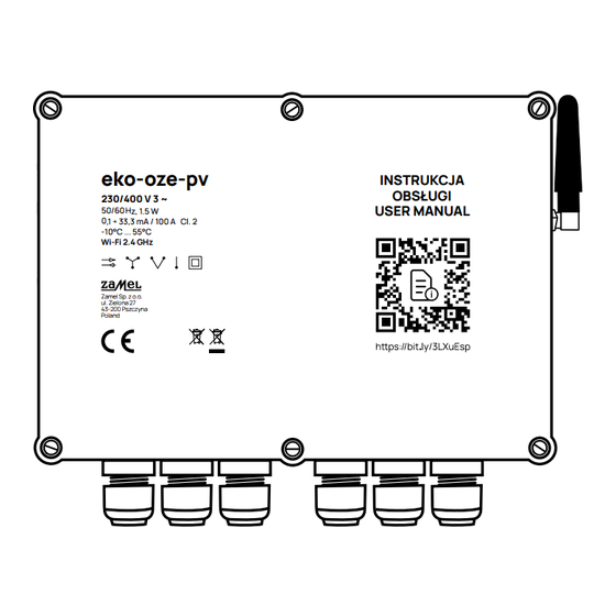
TECHNICAL DATA EKO-01 SET eko-oze-pv Rated voltage: 230 / 400 V 3 ~ Voltage tolerance: – 20% to 15 % Rated power input: 1.5 W Frequency: 50 / 60 Hz Transmission power: ERP < 20 mW Measurement accuracy: Class 2 (±2%) Current transformer parameters: 0.1 –... - Page 9 scr-eko-oze-pv ELECTRICAL SPECIFICATIONS Operating voltage: 24 – 280 V AC Control signal: 4 – 20 mA DC DC Off-state leakage current: < 12 mA Maximum load: 17 A x 3 Insulation breakdown > 2.500 V MECHANICAL SPECIFICATIONS Operating temperature: -20 to +80°C Storage temperature: -40 to +100°C Weight:...
-
Page 10: Tools Required For Installation
TOOLS REQUIRED FOR INSTALLATION screwdriver pliers drill spirit level multimeter hammer 10 mm ring spanner NOTE! The installation should be carried out by a person qualified to carry out electrical work,taking all precautions and respecting the safety regulations provided for the installation of electrical and plumbing equipment. -
Page 11: Mechanical Installation
• scr-eko-oze-pv should be mounted using two 90 degree corners and two 8 x 40 wall plugs. INVERTER eko-oze-pv scr-eko-oze-pv 230/400 V 3 ~ 230/400 V 3 ~ Zamel Sp. z o.o. ul. Zielona 27 Zamel Sp. z o.o. 43-200 Pszczyna ul. Zielona 27 Poland 43-200 Pszczyna... -
Page 12: Electrical Installation
5. Ensure that there is no voltage at the terminals in the switchboard using a suitable measuring instrument. 6. We recommend using the following building automation elements and security: • additional thermostat, e.g. RTM-03 from Zamel (if the heater does not have a built-in thermostat), • contactor, e.g. STM-25-30 from Zamel, •... -
Page 13: Connection Of Eco-Oze-Pv
05.1 CONNECTION OF eko-oze-pv L1 L2 1. A 4-core cable with a cross-section of 0.75 mm must be connected to the L1, L2, L3, N supply terminals , previously protected with an overcurrent protection of not more than 6.3 A (we recommend using our GBM-03 or BZM-03 devices). L1 L2 2. - Page 14 3. Connect the red wires to terminals S1 and the black wires to terminals S2. 4. A very important element is the correct placement of current transformers on the power supply wires on which the measurement is to be conducted (these should be wires directly entering or leaving the residual current device).
- Page 15 5. Connect the supplied temperature sensor to the GND, 1-WIRE, +3.3V terminals. GND – black / blue wire 1-WIRE – yellow wire +3.3V – red wire 6. The measuring point of the sensor must be mounted in the DHW tank (boiler) in such a way that the water temperature can be monitored.
-
Page 16: Connection Of Scr-Eko-Oze-Pv
05.2 CONNECTION OF scr-eko-oze-pv It is recommended that the scr-eko-oze-pv unit is installed as close as possible to the DHW exchanger. This will eliminate the need to run high-current cables, which will re- duce the cost of installation and eliminate the potential risk of electromagnetic inter- ference. - Page 17 2. Run a 4-core cable to be connected to the controllers (SCR 1, SCR 2, SCR 3) – one of the wires is a common cable which is connected to the previously bridged terminals . Connect the following cables to the terminals of the following controllers and to the eco-oze-pv unit, in the following order: SSR 1 terminal –...
-
Page 18: Wiring Diagram
05.3 WIRING DIAGRAM eko-oze-pv S1 S2 S1 S2 S1 S2 L1 L2 OUTPUT OUTPUT OUTPUT scr-eko-oze-pv SCR3 SCR2 SCR1 +12V... -
Page 19: First Start-Up
FIRST START-UP 1. Switch on the main power supply to the switchgear without switching on the inverter. 2. If the unit has not been configured before - the status LED should brighten and dim smoothly, flashing green. LED modes 1. LED lights up •... -
Page 20: With Mobile Application
06.1 The following description applies to device with software 1.0.x. (with mobile application) Updating to the LAVVA application means introducing your eko-oze-pv to a new platform which together with development will affect the functionality of the device. However, with this update the existing integrations which could be controlled with previous configuration page will be lost. - Page 21 LAVVA app. Go to the LAVVA app! After updating your software of eko-oze-pv device download the LAVVA application from Zamel Sp. z o. o. from Google Play. Make sure to choose the version without description „beta”. Lavva – Aplikacje w Google Play If you are not using the Android app, enter the address https://lavva.cloud/ in...
- Page 22 Create an account and follow the instructions on the screen. Remember to provide the address which you use usually. In case you forget your password it will be possible to recover it.
- Page 23 In this step, you need to create a new installation 07/05/2024, 13:05 Page 1 of 1 New installation Change icon Name and locate your installation. Installation name House Main color Color 2 Time zone Europe/Warsaw (GMT+01) Installation location (optional) Please enter a location Next...
- Page 24 07/05/2024, 13:05 Page 1 of 1 Integration Lavva Choose LAVVA integration. Exalus Home Next If the installation is successful you will see this message. Now you can add your device.
- Page 25 Select the search button. A list of devices will appear. Your device will have the note „Lavva” in its name. Important: If you are using a computer, use Chrome or Edge browser. To use the application via a browser it is necessary to enable Experimental Web Platform features.
- Page 26 At this point enter access data to your Wi-Fi network. Congratulations! Clicking “Done” will take you to the main screen.
- Page 27 This is the main screen of your app. At the bottom of the screen You will find the bar with links to subsequent menu sections. 07/05/2024, 13:13 Page 1 of 1 Channels In the Channels section you will find the option to preview and control your List of devices Energy monitoring Optimizer...
- Page 28 05/2024, 13:14 07/05/2024, 13:14 Page 1 of 1 Page 1 of 1 Lavva-Eko-Oze-Pv-F254 Lavva-Eko-Oze-Pv-F254 At this level you have an Optimizer Optimizer access to current datas. Currently Details Configuration Currently Details Configuration You can get more detailed data or go for configuration too.
- Page 29 You can personalize your application in the „Installation settings” tab.
-
Page 30: Without Mobile Application
06.2 The following description applies to the device with software 0.7.x. (without mobile application) 1. You need to connect to a Wi-Fi network with the name eco-oze-pv-xxxx (where xxxx is part of the serial number). Password to access the device 12345678. 2. -
Page 31: Connection To The Local Network
CONNECTION TO THE LOCAL NETWORK 1. In the first step, enable Wi-Fi network search mode by clicking on the refresh icon located in the second tab, Wi-Fi networks section. 2. When the available networks are displayed, select the target network and enter the password. -
Page 32: Network Sharing Mode - Configuration Mode
NETWORK SHARING MODE – CONFIGURATION MODE In this mode it is possible to access the configuration again, e.g. to change the device parameters. This mode is available when any 1 phase or all 3 supply phases are switched off and on 3 times at once. The duration of switching off 1 phase (or 3 phases) must last between 1 s and 10 s. -
Page 33: Description Of The Operation Modes
DESCRIPTION OF THE OPERATION MODES Important! The device requires current transformers to be connected in accordance with the instructions for connecting current transformers. When the eko-oze-pv is used with a DHW storage container heater, a thermostat is required. In each mode, a bar is displayed at the top of the screen with readings of the installation’s current operating parameters. - Page 34 6.12.2023, 08:52 Strona 1 z 1 1. TEST MODE L1 L1 eko-oze-pv eko-oze-pv 7C*87:CE*F3:67:64 230.5V 230.2V 229.9V -0.00kW -0.00kW -0.00kW The installer manually adjusts the value 0.0% 0.0% 0.0% slider to carry out configuration or to acti- Relay 1 OFF Relay 2 OFF Relay 3 OFF 0 kW...
- Page 35 30.11.2023, 08:28 Strona 1 z 1 L1 L1 eko-oze-pv eko-oze-pv 7C*87:CE*F3:67:64 226.7V 0.0V 0.0V Operating the relays 0.00kW 0.00kW -0.00kW 0.0% 0.0% 0.0% When a user-specified power level of Relay 1 OFF Relay 2 OFF Relay 3 OFF 0 kW the heater for a particular phase is ex- ceeded, the relay assigned to that phase Device...
- Page 36 80.0 80.0 Relay 1 OFF Relay 2 OFF Relay 3 OFF 0 kW Voltage threshold L1 NVO frequently, which could contribute Device Device 235.0 235.0 to damage. Current temperature [°C] Voltage threshold L2 NVO 23.7 23.7 230.0 230.0 4. Full self-consumption Operating mode Voltage threshold L3 NVO Full self-consumption...
- Page 37 In the self-consumption mode, operation hours can be set. In the selected time range, the self-consumption function will be executed. The setting has no effect on voltage reduction or minimum tempera- ture maintenance. The function requires a permanent internet connection. Operating the relays In the full self-consumption mode, the re- lays can be tripped.
- Page 38 Current temperature [°C] Voltage threshold L2 PVQ 23.7 23.7 230.0 230.0 5. Self-consumption with a power limit Operating mode In this mode, the user sets the level of Voltage threshold L3 PVQ Self-consumption with power limit power fed to the grid, one above which 225.0 225.0 the surplus is diverted to domestic...
- Page 39 L1 L1 eko-oze-pv eko-oze-pv 7C*87:CE*F3:67:64 227.1V 0.0V 0.0V 0.00kW 0.00kW -0.00kW 6. Self-consumption with relays 0.0% 0.0% 0.0% Relay 1 OFF Relay 2 OFF Relay 3 OFF 0 kW Self-consumption management is also possible in a mode using only Device Device the devices connected by the relays.
-
Page 40: Device Configuration
DEVICE CONFIGURATION eko-oze-pv 94:3C:C6:D9:A4:80 Under the Connections tab, the Wi-Fi Connections Networks field specifies which network the device is connected to; when the Wi-Fi Networks refresh icon (ENTER NUMBER) is clicked, the device will search for available ne- tworks. Select a 2.4 GHz network protected Integrations by a password (the device does not sup- Home Assistant... - Page 41 eko-oze-pv 94:3C:C6:D7:F3:04 Under the Home tab, in the Device name Home field, users can change the default device name to the one of their choice. Device model eko-oze-pv The Software Version field indicates the Device name version the device is running on; if availa- eko-oze-pv ble, an update will be indicated in this field.
- Page 42 -0.00kW -0.00kW -0.00kW 0.0% 0.0% 0.0% Relay 1 OFF Relay 2 OFF Relay 3 OFF 0 kW Device Device Current temperature [°C] The Operating Mode field shows 28.5 28.5 the operating mode of the device. Operating mode Detailed information on the modes TEST MODE is available in the OPERATING MODES TEST MODE...
-
Page 43: Warranty
3. Any warranty claims shall be made by the BUYER at the point of sale or to ZAMEL Sp. z o.o. in writing after the identification of defects. 4. Zamel Sp. z o.o. undertakes to handle complaints in accordance with the applicable provisions of Polish law. - Page 44 Help us to grow Share your opinion https://www.facebook.com /groups/zamelekoozepv/...
- Page 45 SMART SYSTEM Positive energy Zamel Sp. z o.o. ul. Zielona 27, 43-200 Pszczyna, PL tel.: +48 32 210 46 65, +48 32 449 15 00 fax: +48 32 210 80 04 email: marketing@zamel.pl zamel.io/eko-oze-pv www.zamel.com plik: EKO-01_instr(pelna)_GB_0.7.x_1.0.x | ....| v01 | 0.6.0 | modyfikacja: 06.06.2024...
Need help?
Do you have a question about the SC-16 and is the answer not in the manual?
Questions and answers