Table of Contents
Advertisement
Quick Links
Advertisement
Table of Contents

Related Manuals for Halogen MP5

Summary of Contents for Halogen MP5
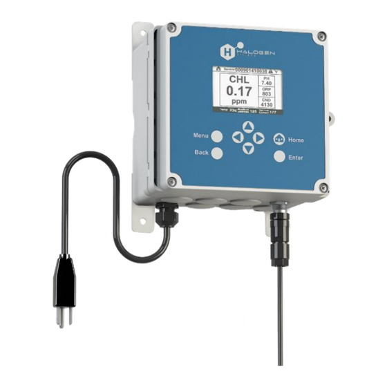
- Page 1 Halogen D20 Display/Controller and MP5 Sensor Installation Guide...
- Page 2 TRADEMARKS The unauthorized use of any trademark displayed in this document or on the product is strictly prohibited. D20 and MP5 are trademarks of Halogen Systems, Inc. Multiple US and worldwide patents have been granted to Halogen Systems, Inc. for its unique features of Chlorine measurement system sensor systems.
-
Page 3: Getting Technical Assistance
I, the undersigned, hereby declare that the equipment specified above conforms to the above Directive and Standard. Place: Reno, Nevada USA (Signature) Date: December 9, 2021 Michael Silveri, President GETTING TECHNICAL ASSISTANCE To get assistance for product installation or commissioning, contact Halogen technical support at tech@halogensys.com. Copyright © 2023 Halogen Systems, Inc. All rights reserved worldwide. -
Page 4: Table Of Contents
Using a flow sensor interlock Installation checklist Troubleshooting/FAQ Appendix A: Halogen D20 Display/Controller Technical Specification Appendix B: Halogen MP5 Sensor Technical Specification Appendix C: Sensors and Accessories Appendix D: Display Options Limited Warranty Index Copyright © 2023 Halogen Systems, Inc. All rights reserved worldwide. -
Page 5: Getting Started
Getting Started Welcome to the Halogen family of products The D20 is a multichannel display/controller for Halogen MP5 and other Halogen sensors. The combination of the Halogen D20 and MP5 represents a proprietary hardware and software system enabling real-time insights and intelligent analysis of onsite water quality. -
Page 6: How To Use This Guide
Note: A best practice alert, tip, or technique that results in successful results. There are five steps to be performed in completing a typical D20 and MP5 installation: 1. Planning: Unbox and inspect the box content and gather tools necessary for installation. Make sure the site is ready for product mounting. -
Page 7: Installation Instructions
Installation Instructions Step 1: Planning To plan for D20 and MP5 installation, become acquainted with the following: ▪ Power and connectivity at the site of the installation ▪ Know what is in the product boxes ▪ Identify the tools necessary to bring onsite for the installation... -
Page 8: What's In The Box
3/8" tubing (push-to-connect) ▪ This installation guide adapters If in the unlikely event that something is missing, contact Halogen Systems before proceeding with the installation. WHAT YOU’LL NEED You’ll need these tools and materials to install the display/controller and the sensor: ▪... -
Page 9: Step 2: Install The D20 Display/Controller
Connect the 4-20mA cabling MOUNT THE ENCLOSURE Place the D20 on a flat surface, like a workbench. The maximum area needed for the D20 enclosure and the opened front cover is shown below: There are two ways to install (mount) the D20 at the site: ▪... -
Page 10: To Mount The D20 To A Pole
TO MOUNT THE D20 TO A POLE Similar to the instructions for mounting the D20 to a wall, attach the controller upright to a pole or pipe with a diameter between 19 to 65 mm (0.75 to 2.5 in) that has either a vertical (L) or horizontal (R) orientation: CONNECT ELECTRICAL CONNECTORS AND FITTINGS At the bottom of the D20 enclosure are the electrical connectors and fittings for the instrument. -
Page 11: Connect The 4-20Ma Wiring
PSU positive (+) or conductivity PSU negative (-) or conductivity Temperature positive (+) Temperature negative (-) pH positive (+) pH negative (-) Note: The 4-20mA connection is not loop powered. Copyright © 2023 Halogen Systems, Inc. All rights reserved worldwide. -
Page 12: Step 3: Set Up Halogen Sensor
The Halogen side stream sensor is a compact device that connects to a drinking water source using ¼" ID tubing. It requires very little flow and is unaffected by changes in the flow rate; however, long tubing may delay readings. -
Page 13: To Install The Flow Cell
(shown below). This orientation ensures that air bubbles properly clear away from the sensor. CONNECT DEVICES TO THE M12 CONNECTOR Connect all digital devices (e.g., sensors and analyzers) to the device connectors on the D20 (see “Connect electrical connectors and fittings”). -
Page 14: Apply Power To The D20
MONITOR THE D20 START-UP PROCESS On the display panel, press on the buttons below the display window to select and enter values on the D20: As the D20 powers up, the display shows a series of status messages like the following: When the D20 power-up is completed, the sensor will start its start-up sequence (L). -
Page 15: Configure Communication
(Optional) To calibrate the outputs: The 4-20mA outputs on the D20 are already calibrated at the factory. If the settings do not match those on your PLC, select 4-20 mA CAL option from the Configuration menu to recalibrate the channel, 4mA, and 20mA values:... -
Page 16: Step 5: Set Up Advanced Features
INSTALL THE SENSOR A flow sensor must be installed and configured in the D20 controller if Chlorine and acid feeds are used. A flow sensor ensures water flow when pumps add chemicals. The controller should be set according to the following: When FLOW NEED is set to a numeric value on the controller, relay activation will only occur when the flow reading exceeds 0. -
Page 17: Using A Flow Sensor Interlock
Flow Sensor Interlock (disabled by default) on the controller. The D20 is designed to work with Gems™ Sensors RFO series flow meters as shown below. (Cables should be wired to block terminals OD and SR.) Copyright © 2023 Halogen Systems, Inc. All rights reserved worldwide. -
Page 18: Installation Checklist
Set the time of day Configure communication Step 5: Set up additional control features Install the sensor, connect to the D20 display/controller, and set up flow sensor interlock Copyright © 2023 Halogen Systems, Inc. All rights reserved worldwide. -
Page 19: Troubleshooting/Faq
Answer happens) How can I check if any fuses With the D20 cover opened, remove the four screws from the high-voltage have blown in the D20? shield (1), remove the shield exposing the underlying PCB (2), and replace any blown fuses (3). Use part number: 5x20mm Slow Blow 3.5A. -
Page 20: Appendix A: Halogen D20 Display/Controller Technical Specification
Digital: Modbus RTU standard SD card Used for data upload, software download, capable of est. 1M data points/sensor Real-time clock Battery, estimated to last 5 years * Subject to change without notice Copyright © 2023 Halogen Systems, Inc. All rights reserved worldwide. -
Page 21: Appendix B: Halogen Mp5 Sensor Technical Specification
24VDC ±10% at 50mA maximum Data transfer Through controller or PLC * Subject to change without notice Specified in 0 to 65,000 µS without calibration 90% at stable temperature and pH Copyright © 2023 Halogen Systems, Inc. All rights reserved worldwide. -
Page 22: Appendix C: Sensors And Accessories
Output connector 2 sensor 1 sensor 2 24VDC FC None North America M12-4 sensor None 24VDC FC None North America M12-4 sensor None 24VDC FC 18 SWG cable None M12-4 sensor None Copyright © 2023 Halogen Systems, Inc. All rights reserved worldwide. -
Page 23: Limited Warranty
In the event that a defect is discovered during the warranty period, Halogen Systems agrees that, at its discretion, it will repair or replace the defective product or refund the purchase price excluding original shipping and handling charges. -
Page 24: Index
13 troubleshooting and FAQ, 15 Gems™ Sensors, 13 warranty, 19 Halogen side stream sensor, 8 what you’ll need, 4 inspection step, 11 what’s included, 4 Copyright © 2023 Halogen Systems, Inc. All rights reserved worldwide.
Need help?
Do you have a question about the MP5 and is the answer not in the manual?
Questions and answers