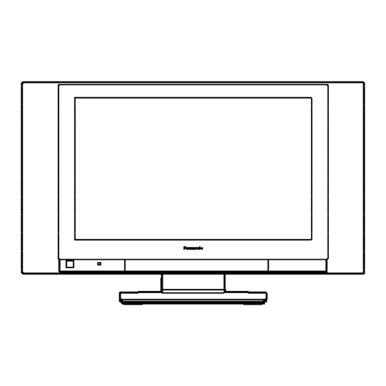
Panasonic TC26LX20 - 26" LCD TV Manual
Hide thumbs
Also See for TC26LX20 - 26" LCD TV:
- Operating instructions manual (52 pages) ,
- Technical manual (56 pages) ,
- Operating instructions manual (52 pages)
Summarization of Contents
1. Safety Precautions
1.1. General Guidelines
General guidelines for servicing, including observing lead dress and installing protective devices.
1.1.1. Leakage Current Cold Check
Procedure for checking leakage current with the AC cord unplugged and a jumper installed.
1.1.2. Leakage Current Hot Check
2. Prevention of Electro Static Discharge (ESD) to Electrostatically Sensitive (ES) Devices
Techniques to prevent component damage from electro static discharge during handling.
4. Self-check function
4.1. How to access
Steps to enter the self-check mode using the remote control and main unit buttons.
4.2. Screen display
Describes the self-check status display on the screen.
6. Before servicing
6.1. Kind and location of the flexible cable
Details the types and locations of flexible cables used for connections.
7. Disassembly for Service
7.1. Rear cover and Stand
Procedures for removing the rear cover and stand assembly.
7.1.1. Rear cover
Step-by-step instructions for removing the rear cover.
7.1.2. Stand and Rear metal frame
Steps for removing the stand assembly and rear metal frame.
8 Adjustment method
8.1. How to enter into adjustment mode
Procedure to access the adjustment mode using the remote control and main unit.
8.2. Cancellation
Method to exit the adjustment mode by switching off the power.
8.3. Contents of adjustment mode
Details on how adjustment values are displayed and the importance of noting them.
8.4. Video Signal Level Adjustment
8.4.1. NTSC picture RF
Procedure for adjusting video signal levels for NTSC RF input.
8.4.2. NTSC picture VBS
Procedure for adjusting video signal levels for NTSC VBS input.
8.6. MTS Adjustment
8.6.1. RF Audio Input level Adjustment
Procedure for setting the RF audio input level for MTS adjustment.
9 Conductor Views
9.1. P-Board
View of the P-Board, showing its layout and connections.
9.2. AP-Board
View of the AP-Board, showing its layout and connections.
9.3. A-Board
View of the A-Board, showing its layout and connections.
9.4. DG-Board
View of the DG-Board, showing its layout and connections.
10 Block and Schematic Diagrams
10.1. Schematic Diagram Notes
Important notes and symbols used in schematic diagrams.
10.2. Power Block Diagram
Diagram illustrating the power distribution and flow within the TV.
10.3. Signal Block Diagram
Diagram showing the flow of signals through different components of the TV.
10.4. P-Board Schematic Diagram
Detailed schematic of the P-Board.
10.5. AP-Board Schematic Diagram
Detailed schematic of the AP-Board.
10.6. A-Board (1 of 3) Schematic Diagram
First part of the detailed schematic for the A-Board.
11 Parts Location & Mechanical Replacement Parts List
11.1. Parts Location
Diagrams showing the physical location of components on the circuit boards.
12 Replacement Parts List
12.1. Replacement Parts List Notes
Notes and explanations regarding the replacement parts list.


Need help?
Do you have a question about the TC26LX20 - 26" LCD TV and is the answer not in the manual?
Questions and answers