
Related Manuals for TLAudio 5050


Summarization of Contents
Installation Guide
AC Mains Supply Connection
Details the IEC connector, wiring, voltage selection, and fuse requirements for powering the unit.
Audio Signal Levels
Explains the input/output compatibility and connection types (TRS jack) for audio equipment.
Microphone Input Details
Describes the 3-pin female XLR connector for balanced/unbalanced microphones and wiring.
Line Input Details
Details the TRS jack socket for balanced/unbalanced line sources and wiring for different levels.
Instrument Input Details
Explains the 2-pin mono jack plug required for instrument connections and its wiring.
Output Connection Details
Describes the balanced line output via a 0.25" TRS jack socket and its wiring for balanced/unbalanced operation.
Unit Mounting Options
Covers free-standing or rack mounting, ensuring ventilation and avoiding heat sources.
Rear Panel Overview
Refers to the rear panel connectors identified in Fig.3 for settings and connections.
Operating the 5050
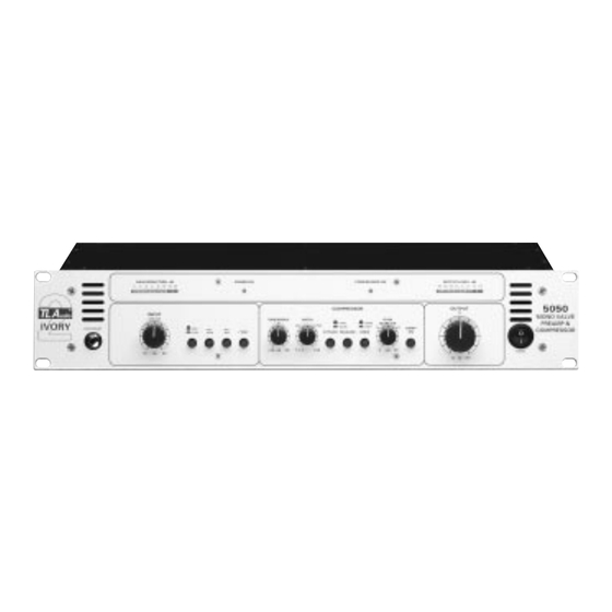
Front Panel Controls
States that front panel controls are identified in Fig.2.
Input Source Selection
Explains how the push button selects mic/line inputs and instrument input priority.
Using the 30dB Pad
Details the use of the 30dB pad for sensitive condenser microphones to reduce input gain.
Phantom Power Application
Describes applying +48V phantom power via the switch and cautions against misuse.
Microphone Input Setup
Advises on setting input gain for microphone sources, starting low and gradually increasing.
Line Input Setup
Guides on setting input gain for line level signals, checking the output meter at 0dB bypass.
Instrument Input Setup
Discusses suitability of the instrument input for various low/high level sources and the need for careful gain staging.
High Pass Filter Function
Explains the function of the HPF to remove low frequencies, rumble, and popping sounds.
Understanding Audio Compression
Defines compression as reducing dynamic range and its historical use versus modern devices.
Benefits of Valve Compression
Explains the unique sound of valve compression from harmonic distortion and natural compression.
Compressor Operation Overview
Briefly touches on how compressors work and their benefits for controlling dynamics and adding character.
Compressor Threshold Control
Defines the Threshold control, its range, and how it initiates compression.
Compressor Ratio Control
Explains the Ratio control, its calibration, and its effect on gain reduction.
Compressor Attack & Release Times
Details the Attack and Release time controls and their impact on compressor response.
Compressor Knee Setting
Describes the Knee switch for soft or hard compression curves and their sonic effects.
Gain Make-Up Adjustment
Explains the Gain Make Up control for restoring level after compression and its interaction with the Compressor On switch.
Compressor On/Off Switch
Explains the switch to enable/disable the compressor for A/B comparison and its status LED.
Output Level Control
Details the Output Fader control for matching output level to equipment, including its gain range.
Bargraph Metering Explained
Describes the twin 8-segment LED bargraph meters for output level and gain reduction.
Optional Digital Output Card
Introduces the optional DO-2 card for digital A/D conversion and SPDIF output.
Getting Started with the 5050
Connecting the 5050
Outlines common connection methods into an audio system, like front end, channel insert, or group insert.
Step-by-Step Usage Guide
Provides a step-by-step guide for setting up and using the 5050 with a condenser microphone.
Technical Specifications
Microphone Input Specifications
Lists specifications for the microphone input, including impedance, gain, noise, and connector type.
Phantom Power Specifications
Specifies the phantom power voltage and maximum current.
High Pass Filter Specifications
Provides the cutoff frequency and slope for the high pass filter.
Balanced Line Input Specifications
Details specifications for the balanced line input, including impedance, gain, and levels.
Auxiliary Input Specifications
Lists specifications for the auxiliary input, including gain control range and maximum input level.
Compressor Specifications
Details the compressor's parameters: Threshold, Attack, Release, Ratio, Gain Make-Up, and Knee modes.
Output Fader Specifications
Describes the output fader's functionality and gain range.
Output Specifications
Specifies the output type, impedance, maximum level, and connector.
Frequency Response
Provides the frequency response characteristics of the unit.
Noise Level
States the noise level specifications for the unit.
Dynamic Range
Details the dynamic range of the unit.
Power Requirements
Covers voltage settings, fuse, power consumption, and power switch details.
Unit Dimensions
Lists the physical dimensions of the unit for rack mounting and overall size.
Shipping Weight
States the shipping weight of the product.
Service and Warranty
Warranty Information
Explains the limited warranty period, coverage, exclusions, and user responsibilities.
Need help?
Do you have a question about the 5050 and is the answer not in the manual?
Questions and answers