Advertisement
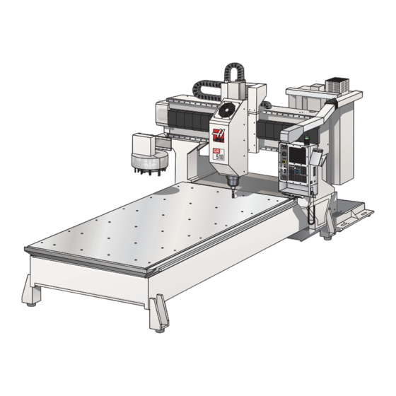
Gantry Router
Operator's Addendum
S
afety
Read and Follow all safety warnings
Manual. Be aware of the other people around you in the shop; lying chips can seriously injure people, who
may not be a safe distance away. Always wear safety glasses. Initial cuts/setups should be cut at a slower
speed to reduce the possibility of tool or machine damage. As with any open frame mill, chip screens are
highly recommended.
This machine must be operated only by trained and qualiied personnel in order to insure a safe environment.
The following precautions are provided to help protect the machine operator against accidents. Every operator
of this machine must read this section and understand the requirements necessary to operate this equipment
in a safe manner. These
guidelines are only available
in English, it is the customer's
responsibility to make non-
English speaking personnel
aware of these guidelines.
Modiications to this machine or
these procedures will not insure
safe operation. The machine
power must be turned OFF prior
to the removal of any panels for
the purpose of service or main-
tenance access.
Any additional guards or safety
devices deemed necessary, are
the sole responsibility of the
machine operator.
The tool changer may start at any time. All personnel must be clear of the tool changer, when the machine is
powered up.
© 2012 Haas Automation, Inc.
- Familiarize yourself with the safety section of the Operator's
STAY CLEAR
STAY CLEAR
A
OPERATOR ZONE
96-0056 rev P 3/12
B
BASE
CASTING
FRONT
C
GR 510/512
A
B
C
COOLANT TANK
DOOR
CONTROL CABINET
GR710/712
36"
36"
36"
48"
30"
42"
1
Advertisement
Table of Contents

Related Manuals for Haas GR 512


Summary of Contents for Haas GR 512
- Page 1 30” 42” machine operator. The tool changer may start at any time. All personnel must be clear of the tool changer, when the machine is powered up. © 2012 Haas Automation, Inc. 96-0056 rev P 3/12...
-
Page 2: Air Requirements
6 GA. Wire 10 GA. Wire NOTE: The gantry mill will perform better when anchored. Refer to the Haas document ES0095 for anchoring instructions. The installation of the Gantry Router is similar to the VF-Series mill (see the VF-Installation section of the Vertical Reference Manual. -
Page 3: Shipping Bracket Removal
Remove the shipping brackets which secure the head to the table. In addition there are shipping bolts which hold the Y-axis to the bridge that need to be removed. Install the sheetmetal cover over the sub-plate, on the tool changer side of the machine. © 2012 Haas Automation, Inc. 96-0056 rev P 3/12... -
Page 4: Shipping Position
2. Remove the tool changer by removing the four bolts which secure the tool changer to the bracket. 3. Turn the tool changer around and reinstall. Leave the bolts loose in order to perform inal alignment © 2012 Haas Automation, Inc. 96-0056 rev P 3/12... -
Page 5: Verify Alignment
90º and check the height again. Do the previous steps again at the 180º and 270º intervals. This will verify that the tool changer assembly is parallel to the table. © 2012 Haas Automation, Inc. 96-0056 rev P 3/12... - Page 6 10. Recheck the offset with the indicator (Steps 1-5). 11. Insert tool holder in spindle taper and change tool. Watch closely as tool changer approaches spindle. 12. Change setting 7 to “ON”. 13. Exit Debug. © 2012 Haas Automation, Inc. 96-0056 rev P 3/12...
- Page 7 Snug the bolts. 2. Move to the bracket with the sensor on it and adjust it until the lights (red and green) on the sensor come on. Do this with both sensors. © 2012 Haas Automation, Inc. 96-0056 rev P 3/12...
- Page 8 5. As process continues, leveling screws are turned in smaller increments — 1/4 turn, 1/8 turn, and smaller. Also, as machine is leveled, make sure tension continues to be equal on the screws at all four corners. © 2012 Haas Automation, Inc. 96-0056 rev P 3/12...
-
Page 9: Tool Changer
• Ensure there is adequate clearance between tools in the tool changer before running an automatic operation. This distance is 3.6” for a 10 pocket or a 20-pocket tool changer. © 2012 Haas Automation, Inc. 96-0056 rev P 3/12... -
Page 10: Coolant Tank
It is possible to put the hoses on the wrong port, so it is very important that the hose are marked properly so they can be reinstalled correctly. Grease Ports Grease Port Grease Ports © 2012 Haas Automation, Inc. 96-0056 rev P 3/12...
Need help?
Do you have a question about the GR 512 and is the answer not in the manual?
Questions and answers