Table of Contents
Advertisement
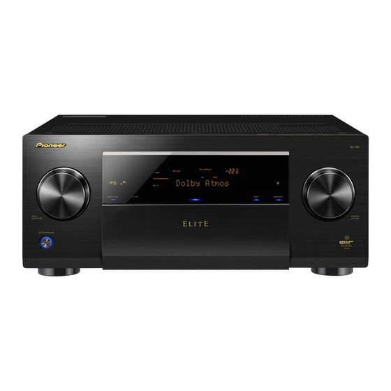
AV RECEIVER
SC-99
SC-97
SC-LX89-K
SC-LX89-S
SC-LX79-K
SC-LX79-S
THIS MANUAL IS APPLICABLE TO THE FOLLOWING MODEL(S) AND TYPE(S).
Model
SC-99
CUXJ
SC-97
CUXJ
SC-LX89-K/-S
SYXJ8
SC-LX79-K/-S
SYXJ8
THIS SERVICE MANUAL SHOULD BE USED TOGETHER WITH THE FOLLOWING MANUAL(S).
Model No.
SC-99, SC-97, SC-LX89-K/-S, SC-LX79-K/-S
PIONEER CORPORATION
PIONEER ELECTRONICS (USA) INC. P.O. Box 1760, Long Beach, CA 90801-1760, U.S.A.
PIONEER EUROPE NV Haven 1087, Keetberglaan 1, 9120 Melsele, Belgium
PIONEER ELECTRONICS ASIACENTRE PTE. LTD. 253 Alexandra Road, #04-01, Singapore 159936
Onkyo & Pioneer Corporation 2015
Type
Power Requirement
AC 120V
AC 120V
AC 220V to 230V
AC 220V to 230V
Order No.
ARP4004
1-1, Shin-ogura, Saiwai-ku, Kawasaki-shi, Kanagawa 212-0031, Japan
SC-99
Remarks
SCHEMATIC DIAGRAM, PCB CONNECTION DIAGRAM
ORDER NO.
RRV4617
Remarks
K-FZV OCT.
2015 Printed in Japan
Advertisement
Table of Contents

Summarization of Contents
Safety Information and Precautions
Safety Precautions
Guidelines for safe servicing and product handling.
Notes on Soldering
Notes on using lead-free solder and appropriate soldering irons.
Notes on Replacing Parts
Guidance on replacing Assy parts instead of discrete components.
Cautionary Notes
Cautionary notes regarding discharging and ground points.
Notes on Assembling
Notes on positioning digital amplifier blocks and screw usage.
Specifications
SC-99 and SC-97 Specifications
Technical specifications for SC-99 and SC-97 models.
SC-LX89 and SC-LX79 Specifications
Technical specifications for SC-LX89 and SC-LX79 models.
Basic Items for Service
Check Points After Servicing
Recommended checks after service to ensure product quality.
PCB Locations
Diagram showing the location of various PCB assemblies within the unit.
Jigs List
List of specialized jigs required for diagnosis and testing.
Block Diagrams
Overall Wiring Diagram
Shows the overall wiring and connections between major blocks.
Block Diagram for Audio Block
Detailed block diagram of the audio processing section.
Block Diagram for Digital Main Video Block
Block diagram focusing on the digital video processing path.
Block Diagram for Digital Main Audio Block
Detailed block diagram of the digital main audio processing.
Block Diagram for Video Block
Block diagram illustrating the video signal flow.
Block Diagram for Power Block (1)
Diagram of the power supply block (part 1).
Block Diagram for Power Block (2)
Diagram of the power supply block (part 2).
Diagnosis Procedures
Diagnosis Flowchart
Step-by-step flowchart for diagnosing issues, starting with 'NO POWER'.
Circuit Description
Details on protection circuit processes like Overheat, DC, Zobel detection.
Error Indications
Lists and explains error codes displayed by the unit.
Network Module Confirmation
Procedure to confirm the Network Module and its connection.
No Sound Troubleshooting
No Sound from Front USB or MHL
Troubleshooting steps for no sound from USB/MHL terminals.
No Sound from HDMI, Media Server, Internet Radio
Troubleshooting no sound from network/internet sources.
No Sound from Bluetooth
Troubleshooting no sound from Bluetooth connections.
No Sound from Tuner
Troubleshooting no sound from the tuner.
No Sound from Multi CH IN
Troubleshooting no sound from multi-channel inputs.
No Sound from USB-DAC
Troubleshooting no sound from USB-DAC.
No Sound in Powerd HD Zone
Troubleshooting no sound in Powerd HD Zone.
No Sound from Network/Wireless Sources
Troubleshooting no sound from Media Server, BT, Wi-Fi.
Audio Assembly Diagnosis
No Sound in Plural Input Modes
Diagnosing no sound in multiple input modes for speaker and preout.
No Sound from Analog Input
Diagnosing no sound from analog input.
No Sound from Headphones
Diagnosing no sound from the headphone output.
No Sound from Zone 2 and Zone 3
Diagnosing no sound from Zone 2 and Zone 3.
No Sound from Zone 2 via Front USB
Diagnosing no sound from Zone 2 via Front USB.
No Sound from Bluetooth
Diagnosing no sound from Bluetooth connections.
No Sound from Tuner
Diagnosing no sound from the tuner.
No Sound from DVR/BDR Output
Diagnosing no sound from DVR/BDR output.
DAC High Assembly Diagnosis
No Sound from Speakers and Preout in EXT STEREO
Diagnosing no sound in EXT STEREO for speaker/preout.
No Sound from Analog Input
Diagnosing no sound from analog input.
No Sound from COAX or OPT Input
Diagnosing no sound from COAX/OPT inputs.
No Sound from Zone 2 via Front USB
Diagnosing no sound from Zone 2 via Front USB.
No Sound from Bluetooth
Diagnosing no sound from Bluetooth connections.
Digital Amp Block Flowchart
No Sound Diagnosis
Flowchart for diagnosing 'No Sound' issues in the Digital Amp Block.
Diagnosis by Error Symptom
Flowcharts for diagnosing specific error symptoms like BERR, OL, DC.
Other Troubleshooting
12V Trigger Troubleshooting
Troubleshooting steps for the 12V trigger function.
RS-232C Troubleshooting
Troubleshooting steps for RS-232C communication.
IR Troubleshooting
Troubleshooting steps for the infrared remote control function.
Service Mode Functions
Detected Protection History
Displays the history of protection detections for various processes.
Disassembly Procedures
Ground Points
Points that must be grounded when the rear panel is removed.
Screws for Rear Panel
List and illustration of screws used for the rear panel.
Front Section Disassembly
Instructions for removing the front section of the unit.
Rear Section Disassembly
Instructions for removing the rear section of the unit.
D AMP ASSY Disassembly
Detailed instructions for removing the D AMP ASSY.
DIGITAL MAIN ASSY and DAC HIGH ASSY Disassembly
Instructions for removing the DIGITAL MAIN ASSY and DAC HIGH ASSY.
Assembling Procedures
Attach D AMP ASSY
Instructions for attaching the D AMP ASSY during reassembly.
Network Module Assembly
Procedure for attaching the Network Module.
Attach IR Cover 85 (MTL)
Steps for attaching the IR Cover 85 (MTL).
Insulator Direction
Procedure for aligning the insulator during reassembly.
Settings and Adjustment
Adjustment After Repair or Replacement
Crucial post-repair steps for specific components.
Exploded Views and Parts List
Packing Section Parts List
Details of parts included in the product packaging.
Exterior Section Parts List
Exploded view and parts list for the exterior section.
Rear Section Parts List
Exploded view and parts list for the rear section.
Chassis Section Parts List
Exploded view and parts list for the chassis section.
Front Section Parts List
Exploded view and parts list for the front section.


Need help?
Do you have a question about the SC-LX89-S and is the answer not in the manual?
Questions and answers