Advertisement
Quick Links
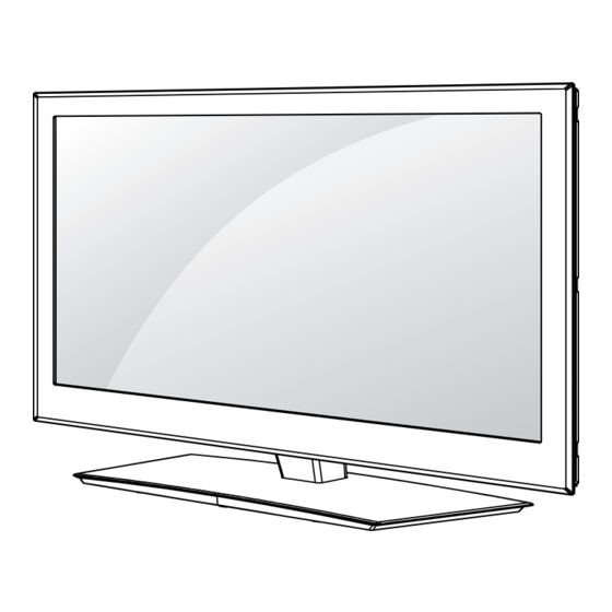
LED LCD TV
SERVICE MANUAL
CHASSIS : LD12C
MODEL: 32LW570G/570S/575S/579S
MODEL:
MODEL:
CAUTION
BEFORE SERVICING THE CHASSIS,
READ THE SAFETY PRECAUTIONS IN THIS MANUAL.
P/NO : MFL67002325 (1104-REV00)
North/Latin America
Europe/Africa
Asia/Oceania
32LW570G/570S-ZD 32LW575S-ZC
32LW579S-ZE
Internal Use Only
http://aic.lgservice.com
http://eic.lgservice.com
http://biz.lgservice.com
Printed in Korea
Advertisement

Summarization of Contents
Safety Precautions
Important Safety Notice
Critical safety warnings and precautions for servicing this chassis to prevent hazards.
General Guidance
Provides essential advice for safe servicing procedures, including transformer use and fuse replacement.
Leakage Current Cold Check (Antenna Cold Check)
Procedure for checking AC leakage current with the set unplugged from the AC source.
Leakage Current Hot Check
Method for measuring AC leakage current with the set plugged into the AC outlet.
Specification
Application Range
Defines the scope of this specification for the LED LCD TV using the LD12C chassis.
Requirement for Test
Outlines environmental conditions and procedures for testing TV components before use.
Test Method
Details the performance and safety test methodologies followed for the TV.
Model General Specification
Lists general specifications by model, including supported countries and broadcasting systems.
Adjustment Instruction
Application Range
Specifies the applicability of these adjustment instructions to LD12C chassis TVs.
Designation
Provides general conditions and guidelines for performing TV adjustments.
ADC Adjustment
Details the process for adjusting Analog-to-Digital conversion for optimal picture quality.
MAC Address
Instructions for setting and verifying the MAC address via RS-232C connection.
LD12C Main PCB for Broadband
0/T/W model
Identifies the main PCB configuration for O/T/W models.
G/S model
Identifies the main PCB configuration for G/S models.
LNB IC Only G/S model
Highlights the presence of an LNB IC specifically for G/S models.
Main processor, DDR Memory Flash Memory
Locates the main processor, DDR memory, and flash memory on the PCB.
Micom for Key/IR sensing
Identifies the micom responsible for key and IR sensing functions.
HDMI switch (4:1)
Locates the HDMI switch IC supporting 4 inputs.
Audio AMP (10W+10W)
Identifies the location of the audio amplifier with 10W+10W output.
URSA5 External FRC
Points out the location of the URSA5 external Frame Rate Controller.
Interconnection - 1
Main PCB
Identifies the main printed circuit board.
Power Board
Locates the power supply board.
Soft touch + IR Key PCB
Identifies the PCB for soft touch buttons and IR receiver.
Main / PSU cable
Shows the cable connecting the main board to the power supply unit.
Main / Module LVDS cable 41&51PIN
Details the LVDS cable connecting the main board to the T-con module.
LED driver / PSU
Locates the component responsible for LED backlight control.
15Pin (IR+Touch) Cable
Identifies the cable for IR and touch panel functions.
SPK Cable
Shows the cable connecting the speakers.
Local Dimming Cable
Identifies the cable for the local dimming function.
Interconnection - 2
Main PCB
Identifies the main printed circuit board for 32/37 inch models.
Power Board
Locates the power supply board for 32/37 inch models.
Soft touch + IR Key PCB (LW570 only IR Assy)
Identifies the soft touch and IR PCB, noting LW570 specific IR Assy.
Main / PSU cable
Shows the cable connecting the main board to the power supply unit.
Main / Module LVDS cable 41&51PIN
Details the LVDS cable connecting the main board to the T-con module.
LED driver / PSU
Locates the component responsible for LED backlight control.
15Pin (IR+Touch) Cable
Identifies the cable for IR and touch panel functions.
SPK Cable
Shows the cable connecting the speakers.
Local Dimming Cable
Identifies the cable for the local dimming function.
Standard Repair Process
A. Video error
Troubleshooting steps for video-related issues like no video or color problems.
B. Power error
Diagnostic procedures for the TV experiencing no power or intermittent power.
C. Audio error
Steps to resolve issues with no audio or distorted audio output.
D. General Function Problem
Troubleshooting external device recognition and remote control malfunctions.
E. Noise
Identifying and resolving circuit or mechanical noise issues in the TV.
F. Exterior defect
Procedures for addressing physical damage to the TV or its accessories.


Need help?
Do you have a question about the 32LW570S and is the answer not in the manual?
Questions and answers