Table of Contents
Advertisement
All manuals and user guides at all-guides.com
SERVICE MANUAL
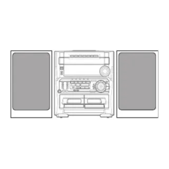
COMPACT DISC STEREO
CASSETTE RECEIVER
SYSTEM
CASSEIVER
CX-ZL700
Z-L700
Z-L800
CX-ZL800
• This Service Manual is the "Revision Publishing" and replaces "Simple Manual"
Z-L700 (U) / Z-L800 (LH), (S/M Code No. 09-002-422-7T1).
• If requiring information about the CD mechanism, see Service Manual of 6ZG-1,
(S/M Code No. 09-001-338-7N2).
• If requiring information about the Stereo Turntable, see Service Manual of
PX-E860 (U), (S/M Code No. 09-993-322-0R1).
Z-L700
Z-L800
BASIC TAPE MECHANISM : 2ZM-3MK2 PR5NM
BASIC CD MECHANISM : 6ZG-1 ZRDM
CD
SPEAKER
SX-WZL700
SX-WZL800
S/M Code No. 09-004-422-7R1
U
LH
STEREO
REMOTE
TURNTABLE
CONTROLLER
PX-E860
RC-ZAS12
-
Advertisement
Table of Contents

Summarization of Contents
Service Manual Overview
System Identification
Identifies system models (Z-L700, Z-L800) and main components.
Product Specifications
Tuner and Amplifier Specs
Details specifications for FM/AM tuners and the amplifier section.
Player, Deck, Speaker Specs
Lists specifications for CD player, cassette deck, and speakers.
Safety Precautions
Laser Safety During Servicing
Essential precautions to prevent eye exposure to laser radiation.
Optical Block Replacement Precautions
Notes on preventing damage to the laser diode during replacement.
Repair Procedures
Capacitor Discharge Procedure
Step-by-step guide for safely discharging electrolytic capacitors.
Microcomputer Troubleshooting
Microcomputer Reset and Checks
Procedures for microcomputer reset, HOLD terminal check, and soldering confirmation.
Component Information
Chip Resistor Coding
Explains the coding system used for chip resistors.
Component Illustrations
Transistor Illustrations
Visual diagrams showing common transistor pinouts and types.
Integrated Circuit Details
IC Block Diagrams
Block diagrams and pinouts for key integrated circuits.
Service Adjustments - Tuner Section
Tuner Adjustments
Procedures for calibrating tuner functions like frequency and tracking.
Service Adjustments - Deck Section
Deck Adjustments
Steps for adjusting tape speed, azimuth, and frequency response.
Front Section Adjustments
Instructions for adjusting the MICON OSC in the front control section.
Mechanical Views
Main Unit Exploded View
Visual breakdown of the main unit's components and assembly.
Mechanical Parts Lists
Main Mechanical Parts List
Comprehensive list of mechanical part numbers for the main unit.
Tape Mechanism Views
Tape Mechanism Exploded View
Detailed breakdown of the tape mechanism assembly.
Tape Mechanism Parts List
Tape Mechanism Parts List
List of part numbers for the tape mechanism components.
Speaker Service
Speaker Disassembly Instructions
Guides for taking apart speaker units and panels.
Speaker Parts List
Speaker Parts List
List of parts specific to the included speaker systems.


Need help?
Do you have a question about the CX-ZL700 and is the answer not in the manual?
Questions and answers