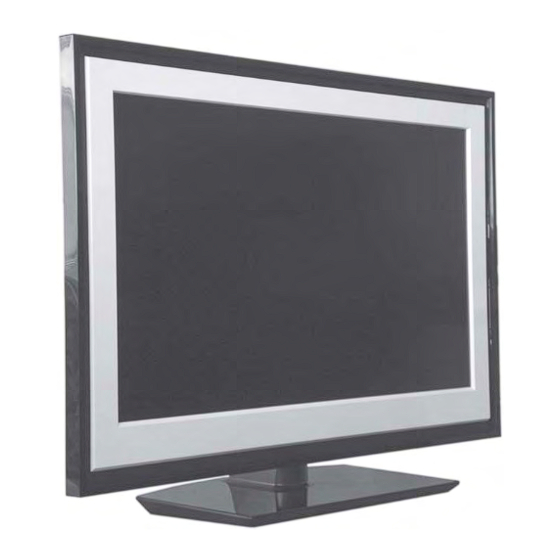
Sony KDL-40E5500 Service Manual
Flat panel color tv
Hide thumbs
Also See for KDL-40E5500:
- Operating instructions manual (57 pages) ,
- Instruction & operation manual (119 pages)
Summarization of Contents
SECTION 1 GENERAL
General Cautions and Warnings
Safety precautions for servicing, UK plug, and LCD panel handling.
HIROSE MDF61 Connector Handling
Insertion and Detachment Procedures
Step-by-step guide for connecting and disconnecting HIROSE MDF61 connectors.
Product Specifications
Power, Dimensions, and Mass
Detailed technical specifications including power requirements, dimensions, and weight.
System and Signal Information
TV System and Input Signals
Details on TV system types, video standards, channel bands, and PC/HDMI input signals.
Component Connectors
SCART, HDMI, and D-Sub Pinouts
Pin assignments and signal details for SCART, HDMI, and D-Sub connectors.
EX2L Self Diagnostic Software
LED Error Codes and Descriptions
Explanation of LED flash codes for identifying system errors and their meanings.
SECTION 2 DISASSEMBLY
Rear Cover and Stand Assy Removal
Procedures for removing the rear cover and stand assembly.
Under Cover and Switch Unit Removal
Steps for removing internal covers and the switch unit.
Loudspeaker, BA, G2, IP1 Board Removal
Procedures for disassembling key internal boards and components.
HLG and HSN Board Removal
Steps for removing the HLG and HSN boards from the unit.
SECTION 3 SERVICE MENUS
Service Mode Entry and Data Management
Instructions on accessing, navigating, and managing TVM data in service mode.
EX2L Block Diagram
Overall System Architecture
Visual representation of the TV's main functional blocks and their interconnections.
Circuit Board Locations and Schematics
Board Identification and Schematic Notes
Visual guide to board locations and notes on interpreting schematic diagrams.
Indicator and Sensor Boards
HLG LED and HSN Sensor Schematics
Schematic details for the HLG LED indicator and HSN Light/IR sensor.
IP1 Board Schematic Diagram
Inverter and Power Supply Schematics
Detailed schematics for the IP1 board's inverter and power supply sections.
Printed Wiring Board Layouts
BA and HLG Board Layouts
Visual layout diagrams for the BA and HLG main circuit boards.
BA and HSN Board Layouts
Visual layout diagrams for the BA and HSN main circuit boards.
IP1 Board Layout Diagram
Visual layout diagram for the IP1 main circuit board.
SECTION 5 EXPLODED VIEWS
Chassis Component Identification
Exploded view showing the location and part numbers of chassis components.
Bezel and Stand Assembly
Exploded view detailing the bezel and stand assembly parts.
Rear Cover and Power Supply Cords
Exploded view showing rear cover and power cord components.
SECTION 6 ELECTRICAL PARTS LIST
Parts Listing Table of Contents
Index of available parts lists for various boards and accessories.


Need help?
Do you have a question about the KDL-40E5500 and is the answer not in the manual?
Questions and answers