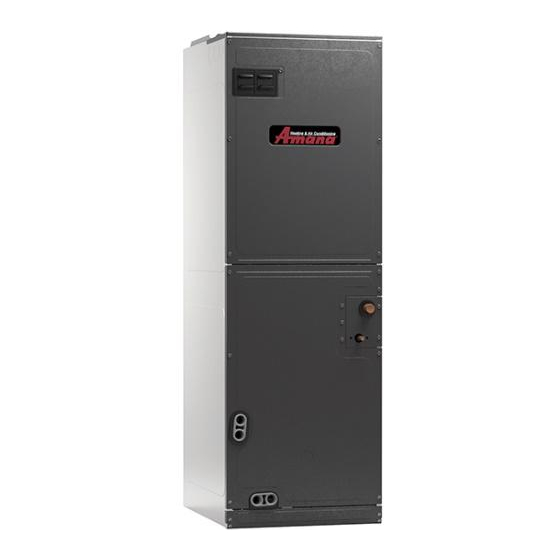
Table of Contents
Advertisement
ARUF**14** / ASPT**14**
AIR HANDLERS INSTALLATION &
OPERATING INSTRUCTIONS
TABLE OF CONTENTS
1 Important Safety Instructions .................................... 1
2 Shipping Inspection ................................................... 3
2.1 Parts ...................................................................... 3
2.2 Handling ................................................................ 3
3 Codes & Regulations ................................................. 3
4 Replacement Parts ..................................................... 3
5 Pre-Installation Considerations ................................ 3
5.1 Preparation ............................................................ 3
5.2 System Matches .................................................... 3
5.3 Interconnecting Tubing .......................................... 3
5.4 Clearances ............................................................ 3
5.5 Horizontal Applications .......................................... 3
5.6 Access ................................................................... 4
6 Installation Location ................................................... 4
6.1 Upflow Installation ................................................. 4
6.2 Horizontal Left Installation ..................................... 4
Downflow Installation ............................................. 5
7 Refrigerant Lines ........................................................ 6
7.1 Tubing Size ............................................................ 6
7.2 Tubing Preparation ................................................ 6
7.3 Special Instructions ............................................... 6
7.4 Tubing Connections for Flowrator Model ............... 8
7.5 Tubing Connections for TXV Models ..................... 8
8 Condensate Drain Lines ........................................... 10
9 Ductwork .................................................................... 10
9.1 Return Ductwork ........................................................ 11
10 Return Air Filters ..................................................... 11
11 Electric Heat ............................................................. 11
12 Electrical and Control Wiring ................................. 12
12.1 Building Electrical Service Inspect ...................... 12
12.2 Wire Sizing.......................................................... 12
12.3 Maximum Overcurrent Protection (MOP) ........... 12
12.4 Electrical Connections - Supply Voltage ............ 14
Do not bypass safety devices.
RECOGNIZE THIS SYMBOL
AS A SAFETY PRECAUTION
NOTE: SPECIFICATIONS AND PERFORMANCE DATA LISTED HEREIN
ARE SUBJECT TO CHANGE WITHOUT NOTICE
WARNING
is a registered trademark of Maytag Corporation or its related companies and is used under license.
© 2014-2018, 2020-2023
Daikin Comfort Technologies Manufacturing, L.P.
19001 Kermier Rd., Waller, TX 77484
www.goodmanmfg.com -or- www.amana-hac.com
P/N: IO-901N Date: April 2023
Only personnel that have been trained to install, adjust,
service, maintenance or repair (hereinafter, "service")
the equipment specified this manual should service the
equipment.
This equipment is not intended for use by persons
(including children) with reduced physical, sensory or
mental capacities, or lack of experience and knowledge,
unless they have been given supervision or instruction
concerning use of the appliance by a person responsible
for their safety.
Children should be supervised to ensure that they do not
play with the equipment.
The manufacturer will not be responsible for any injury
or property damage arising from improper supervision,
service or service procedures. If you service this unit, you
assume responsibility for any injury or property damage
which may result. In addition, in jurisdictions that require
one or more licenses to service the equipment specified in
this manual, only licensed personnel should service the
equipment. Improper supervision, installation, adjustment,
servicing, maintenance or repair of the equipment specified
in this manual, or attempting to install, adjust, service
or repair the equipment specified in this manual without
proper supervision or training may result in product
damage, property damage, personal injury or death.
AS A SAFETY PRECAUTION.
All rights reserved.
WARNING
RECOGNIZE THIS SYMBOL
Advertisement
Table of Contents

Summarization of Contents
Important Safety Instructions
Shipping Inspection
Verify unit condition and components upon receipt for damage or missing parts.
Codes & Regulations
Installation must comply with applicable national, local, and state codes and regulations.
Replacement Parts
Use only factory-authorized parts and provide model/serial numbers when ordering.
Pre-Installation Considerations
Read all instructions, gather tools, and ensure all necessary supplies are on hand before installation.
Installation Location
Upflow and Downflow Installation
Details the steps for removing and reinstalling the coil assembly for upflow and downflow configurations.
Horizontal Left Installation
Instructions for installing the unit in a horizontal left orientation, including drain port usage.
Horizontal Right Installation
Steps for installing the unit in a horizontal right orientation, including coil assembly and drain connections.
Refrigerant Lines
Tubing Size and Preparation
Follow specifications for tubing size and ensure proper preparation for leak-free connections.
Special Instructions and Connections
Guidance for flowrator pistons, TXV models, and specific ASPT**14** charging methods.
Thermal Expansion Valve System Adjustment
Procedure for adjusting TXV for proper subcooling and superheat in cooling and heating modes.
Electrical and Control Wiring
Building Electrical Service Inspection
Verify single-phase power supply and agreement with unit nameplate requirements.
Wire Sizing and Protection
Guidelines for selecting appropriate wire size, overcurrent protection, and voltage drop.
Supply Voltage Connections
Details on connecting supply voltage conductors, using copper wire, and approved strain relief.
Low Voltage Connections
Guidance on low voltage wiring for various configurations, thermostat connections, and wire gauge.
Speed Tap Adjustment
Procedure for adjusting the blower motor speed using speed taps on the control board.
Wiring Diagrams
Low Voltage Wiring Diagrams
Illustrates low voltage connections for ARUF air handlers in cooling, heat pump, and electric heat configurations.
Electronic Blower Time Delay Relay Diagram
Diagram and explanation of the electronic blower time delay relay operation and timing.
High Voltage Wiring Diagrams
Diagrams illustrating high voltage wiring for ARUF and ASPT models, including motor and transformer connections.
3-Phase Heat Kit Wiring Diagram
Wiring diagram for a 3-phase heat kit, showing connections to power supply, heat elements, and control components.


Need help?
Do you have a question about the ASPT37C14 and is the answer not in the manual?
Questions and answers