Advertisement
Quick Links
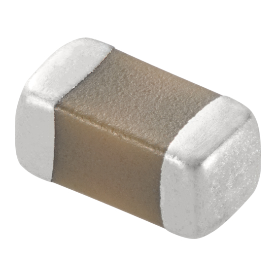
Chip Monolithic Ceramic Capacitor for General
GRM155R71H104KE14_ (0402, X7R:EIA, 0.1uF, DC50V)
_: packaging code
1.Scope
This product specification is applied to Chip Monolithic Ceramic Capacitor used for General Electronic equipment.
2.MURATA Part NO. System
(Ex.)
GRM
15
(1)L/W
Dimensions
3. Type & Dimensions
(1)-1 L
(1)-2 W
1.0±0.05
0.5±0.05
4.Rated value
(3) Temperature Characteristics
(Public STD Code):X7R(EIA)
Temp. coeff
or Cap. Change
-15 to 15 %
5.Package
mark
(8) Packaging
f180mm Reel
D
PAPER W8P2
f180mm Reel
W
PAPER W8P1
f330mm Reel
J
PAPER W8P2
Product specifications in this catalog are as of Mar.8,2016,and are subject to change or obsolescence without notice.
Please consult the approval sheet before ordering.
Please read rating and !Cautions first.
GRM155R71H104KE14-01
5
R7
(2)T
(3)Temperature
Dimensions
Characteristics
(2) T
e
0.5±0.05
0.15 to 0.35
(4)
Rated
Temp. Range
Voltage
(Ref.Temp.)
-55 to 125 °C
DC 50 V
(25 °C)
Packaging Unit
10000 pcs./Reel
20000 pcs./Reel
50000 pcs./Reel
1H
104
(4)Rated
(6)Capacitance
(5)Nominal
Voltage
Capacitance
(Unit:mm)
g
0.3 min.
Specifications and Test
(6)
(5) Nominal
Capacitance
Capacitance
Tolerance
0.1 uF
±10 %
1
Reference Sheet
K
E14
(7)Murata's Control
(8)Packaging Code
Tolerance
Code
Methods
(Operating
Temp. Range)
-55 to 125 °C
D
Advertisement

Summarization of Contents
Specifications and Test Methods
Rated Voltage
Specifies the maximum allowable voltage for the capacitor.
Appearance
Describes the visual inspection criteria for defects.
Dimension
Details the physical dimensions and measurement methods.
Voltage proof
Specifies the test for dielectric strength and breakdown voltage.
Insulation Resistance (I.R.)
Defines the minimum acceptable insulation resistance value.
Capacitance
Specifies capacitance measurement conditions and values.
Dissipation Factor (D.F.)
Defines the maximum allowable dissipation factor.
Temperature Characteristics of Capacitance
Describes how capacitance changes with temperature variations.
Adhesive Strength of Termination
Tests the bonding strength of the capacitor terminations.
Vibration
Outlines vibration testing conditions and acceptance criteria.
Substrate Bending test
Evaluates capacitor performance under PCB bending stress.
Solderability
Tests the ability of terminations to be soldered effectively.
Resistance to Soldering Heat
Assesses capacitor integrity after exposure to soldering heat.
Temperature Sudden Change
Tests capacitor performance under rapid temperature fluctuations.
High Temperature High Humidity (Steady)
Evaluates capacitor stability under sustained high temperature and humidity.
Durability
Assesses long-term reliability under specified conditions.
Package GRM Type
Tape Carrier Packaging
Details packaging codes, reel types, and minimum quantities.
Dimensions of Tape
Provides tape dimensions for GRM01/02.
GRM03/15(W8P2 CODE:D/E/J/F)
Tape dimensions and chip sizes for specific GRM series.
GRM033/155(W8P1 CODE:W)
Tape dimensions and chip sizes for specific GRM series.
GRM18/21/31/32
Tape dimensions and chip sizes for specific GRM series.
GRM43/55
Tape dimensions and chip sizes for specific GRM series.
Component Rating Overview
Temperature Dependent Characteristics
Describes how capacitor characteristics change with temperature.
Soldering and Mounting Best Practices
Mounting Position Optimization
Guidance on optimal component placement to minimize stress.
Pre-Mounting Checks and Considerations
Key checks and considerations before component assembly.
Assembly Process Guidelines
Component Handling
Precautions for handling boards with mounted components.
Mounting Other Components
Considerations when mounting components on the opposite side of the PCB.
Inserting Leaded Components
Steps to avoid stress when inserting leaded components.
Socket Attachment/Removal
Advice on attaching/removing sockets without bending the board.
Screw Tightening Precautions
Precautions for tightening screws to avoid board bending.
Operational and Disposal Notes
Operation Environment Guidelines
Safety guidelines for operating equipment with the product.
General Notes and Disposal
General notes including emergency procedures and disposal.
Rating Parameters
Operating Temperature
Defines the operational temperature limits and factors to consider.
Atmosphere Surroundings (gaseous and liquid)
Restrictions on environmental conditions for capacitor operation.
Piezo-electric Phenomenon
Discusses vibration and noise generation in capacitors.
PCB Design Considerations
Pattern Form Notices
Guidelines for PCB layout and pattern design to prevent cracking.
Transportation and System Evaluation
Transportation Guidelines
Guidelines for protecting capacitors during transportation.
Actual System Evaluation
Importance of evaluating performance in the actual system.


Need help?
Do you have a question about the GRM155R71H104KE14D and is the answer not in the manual?
Questions and answers