
Related Manuals for Panasonic NV-VZ17EN


Summarization of Contents
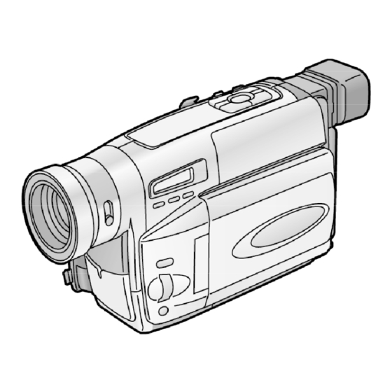
1. INTRODUCTION
1.1. INTRODUCTION
Technical information for service personnel to understand and service the model.
1.2. ABOUT LEAD FREE SOLDER (PbF)
Cautions and guidelines for using lead-free solder in repairs.
2. CAUTION FOR AC CORD (VJA0940 TYPE)
2.1. INFORMATION FOR YOUR SAFETY
General safety information, including copyright warnings and product usage advice.
2.2. CAUTION FOR AC MAINS LEAD
Safety precautions for the AC power cord, plug, and fuse replacement.
3. SERVICE CAUTION
3.1. SERVICE EXTENSION CABLES
Lists required extension cables for servicing connections.
3.2. SET-UP FOR ADJUSTMENT OF TATSUJIN
Instructions for setting up the "TATSUJIN" adjustment using a small cover.
4. SERVICE INFORMATION
4.1. EMAGENCY DISPLAY
Explains emergency error displays (e.g., E01) and their impact on operations.
6. ADJUSTMENT PROCEDURES
6.1. DISASSEMBLY PROCEDURES
Provides a flow-chart and steps for camcorder disassembly.
6.2. DISASSEMBLY PROCEDURES OF LENS UNIT
Describes flowchart for removing lens units and circuit boards for service.
7. BLOCK DIAGRAMS
7.1. POWER SYSTEM BLOCK DIAGRAM
Block diagram for the power system.
7.2. CPU/MDA SYSTEM BLOCK DIAGRAM
Block diagram for the CPU/MDA system.
7.3. CAMERA AND Y/C SYSTEM BLOCK DIAGRAM
Block diagram for the camera and Y/C system.
7.4. MONITOR SYSTEM BLOCK DIAGRAM
Block diagram for the monitor system.
8. SCHEMATIC DIAGRAMS
8.1. BOARD INTERCONNECTIONS
Schematic showing signal connections between different boards.
8.2. CPU SCHEMATIC DIAGRAM
Detailed schematic diagram of the camcorder's CPU section.
8.3. M.MDA SCHEMATIC DIAGRAM
Detailed schematic diagram of the camcorder's M.MDA section.
8.4. VTR ASP SCHEMATIC DIAGRAM
Detailed schematic diagram of the camcorder's VTR ASP section.
8.5. DSP SCHEMATIC DIAGRAM
Detailed schematic diagram of the camcorder's DSP section.
8.6. F/Z/I/MDA SCHEMATIC DIAGRAM
Detailed schematic diagram of the camcorder's F/Z/I/MDA section.
8.7. V OUT SCHEMATIC DIAGRAM
Detailed schematic diagram of the camcorder's V OUT section.
8.8. TG/CDS SCHEMATIC DIAGRAM
Detailed schematic diagram of the camcorder's TG/CDS section.
8.9. REG SCHEMATIC DIAGRAM
Detailed schematic diagram of the camcorder's REG section.
8.10. LCD SCHEMATIC DIAGRAM
Detailed schematic diagram of the camcorder's LCD section.
8.11. BWVF SCHEMATIC DIAGRAM
Detailed schematic diagram of the camcorder's BWVF section.
8.12. JACK SCHEMATIC DIAGRAM
Detailed schematic diagram of the camcorder's JACK section.
8.13. SPEAKER SCHEMATIC DIAGRAM
Detailed schematic diagram of the camcorder's SPEAKER section.
8.14. CCD SCHEMATIC DIAGRAM
Detailed schematic diagram of the camcorder's CCD section.
8.15. MONITOR SCHEMATIC DIAGRAM
Detailed schematic diagram of the camcorder's MONITOR section.
8.16. FRONT SCHEMATIC DIAGRAM
Detailed schematic diagram of the camcorder's FRONT section.
8.17. REAR SCHEMATIC DIAGRAM
Detailed schematic diagram of the camcorder's REAR section.
8.18. SENSOR SCHEMATIC DIAGRAM
Detailed schematic diagram of the camcorder's SENSOR section.
8.19. 0 LUX SCHEMATIC DIAGRAM
Detailed schematic diagram of the camcorder's 0 LUX section.
8.20. WAVEFORM TABLE
Table showing waveforms for ICs with voltage and time details.
8.21. VOLTAGE CHARTS
Charts detailing pin voltages in different operating modes.
9. CIRCUIT BOARD ASSEMBLIES
9.1. MAIN C.B.A. (FOIL SIDE)
Diagram of the main circuit board assembly, foil side layout.
9.2. MAIN C.B.A. (COMPONENT SIDE)
Diagram of the main circuit board assembly, component side layout.
9.4. MONITOR C.B.A.
Diagram of the monitor circuit board assembly.
9.5. FRONT C.B.A.
Diagram of the front circuit board assembly.
10. EXPLODED VIEWS
10.1. FRAME& CASING SECTION
Exploded view of the camcorder's frame and casing assembly.
10.2. MONITOR SECTION
Exploded view of the camcorder's monitor section assembly.
10.3. CAMERA LENS SECTION
Exploded view of the camcorder's camera lens section assembly.
10.4. EVF SECTION
Exploded view of the camcorder's EVF section assembly.
10.5. MECHANISM SECTION
Exploded view of the camcorder's mechanism section assembly.
10.6. PACKING PARTS& ACCESSORIES SECTION
Exploded view of packing parts and included accessories.
11. REPLACEMENT PARTS LIST
11.1. MECHANICAL REPLACEMENT PARTS LIST
Comprehensive list of mechanical parts available for replacement.
11.1.1. FRAME& CASING SECTION PARTS LIST
Specific parts list for frame and casing components.
11.1.2. MONITOR SECTION PARTS LIST
Specific parts list for monitor section components.
11.1.3. CAMERA LENS SECTION PARTS LIST
Specific parts list for camera lens section components.
11.1.4. EVF SECTION PARTS LIST
Specific parts list for EVF section components.
11.1.5. MECHANISM SECTION PARTS LIST
Specific parts list for mechanism section components.
11.1.6. PACKING PARTS& ACCESSORIES SECTION PARTS LIST
Specific parts list for packing parts and accessories.
Need help?
Do you have a question about the NV-VZ17EN and is the answer not in the manual?
Questions and answers