Table of Contents
Advertisement
Quick Links
®
™
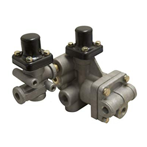
Bendix
SR-4
Spring Brake Control Valve
#1
RESERVOIR
CHARGING
PORT
DELIVERY PORTS (4)
FIGURE 1A
™
FIGURE 1 - SR-4
SPRING BRAKE CONTROL VALVE TYPE 1 & TYPE 2
DESCRIPTION
™
The SR-4
valve is provided in two different confi gurations.
Type 1 (Fig. 1A) incorporates a nipple mounted PR-3
valve. Type 2 (Fig. 1B) has the function of the additional
™
PR-3
valve integrated into the main housing. There is
no difference in the operational performance of the two
designs.
™
The SR-4
trailer spring brake control valve is similar
™
to the SR-2
valve. It differs in function by utilizing both
reservoirs for normal service braking but reserving suffi cient
air pressure to provide the required spring brake release in
the event of a service system failure. As seen in Fig. 1, the
complete assembly includes an SR-4
similar in appearance to an SR-2
subassembly is an SR-2
of a check valve in the spring brake reservoir fi tting which
permits air to pass from the reservoir to the spring brake
inlet valve but not in the opposite direction. AT NO TIME
SHOULD AN SR-2
™
VALVE BE SUBSTITUTED FOR THE
™
SR-4
VALVE SUBASSEMBLY. The SR-4
identifi ed by the metal tag affi xed to the cover by one of
four cap screws. Porting is as follows:
#2 RESERVOIR
CHARGING
PORT
SERVICE PORT
TRAILER SUPPLY
PORT
TYPE 1
™
valve sub-assembly
™
valve. The SR-4
™
valve modifi ed by the addition
™
valve may be
#1
RESERVOIR
CHARGING
PORT
DELIVERY
PORTS (4)
FIGURE 1B
• 1/2 inch NPT or 3/4 inch NPT spring brake supply port
™
for reservoir mounting
• 4-3/8 inch NPT delivery ports
• 2-1/4 inch NPT reservoir charging ports
• 1-1/4 inch NPT trailer supply port
• 1-1/4 inch NPT service port (optional)
OPERATION (FIG. 2)
CHARGING
Air from the trailer supply line enters at the trailer supply port
and depresses the control piston "D", opening the spring
™
valve
brake inlet valve "E". It also is conducted to the cavity under
the pressure protection piston "F". When air pressure builds
to approximately 60 p.s.i. beneath the pressure protection
piston, the piston moves against the force of the pressure
protection spring and opens the pressure protection inlet
valve. The air pressure now fl ows past check valve "A"
into the #2 reservoir and past check valve "B" through the
open spring brake inlet valve and into the spring brake
#2 RESERVOIR
CHARGING
PORT
SERVICE PORT
TRAILER SUPPLY
PORT
TYPE 2
1
Advertisement
Table of Contents

Related Manuals for BENDIX SR-4 SPRING BRAKE CONTROL VLV


Summary of Contents for BENDIX SR-4 SPRING BRAKE CONTROL VLV
- Page 1 ® ™ Bendix SR-4 Spring Brake Control Valve #2 RESERVOIR CHARGING PORT #2 RESERVOIR CHARGING RESERVOIR PORT CHARGING PORT SERVICE PORT SERVICE PORT RESERVOIR CHARGING PORT DELIVERY DELIVERY PORTS (4) PORTS (4) TRAILER SUPPLY TRAILER SUPPLY PORT PORT FIGURE 1A...
- Page 2 SERVICE LINE PRESSURE PROTECTION PISTON SPRINGS ANTI-COMPOUND PRESSURE LINE PROTECTION INLET VALVES PRESSURE PROTECTION PISTON "F" PRESSURE PROTECTION PISTON "F" CHECK VALVE “A” CHECK VALVE "G" RES. CHECK VALVE “B” RES. ANTI-COMPOUNDING CHECK VALVE SUPPLY PORT RELAY VALVE CHECK VALVE “C” TRAILER SUPPLY LINE SPRING BRAKE CONTROL PISTON "D"...
- Page 3 Note: As system pressure reaches approximately 60 p.s.i., the #2 reservoir and the spring brakes Important: Review the Bendix Warranty Policy before should build up to approximately 60 p.s.i. before performing any intrusive maintenance procedures. A the #1 reservoir begins to charge (see Fig. 3).
- Page 4 AD-IS air dryer system or a dryer reservoir module, ™ or replaced at the nearest Bendix distributor. The PR-3 be sure to drain the purge reservoir. valve is not considered as serviceable internally. If 5. Following the vehicle manufacturer’s recommended ™...
- Page 5 CHECK VALVE “A” CHECK VALVE “B” METAL I.D. CHECK VALVE “C” EXHAUST (17 - SCREW) PORT (18 - WASHER) IF EQUIPPED (19 - DIAPHRAGM) FIGURE 4 ™ SR-4 VALVE DISASSEMBLY (TYPE 1 REFER TO FIG. 4) 7. Remove the reservoir port fi tting (13) from the valve REMOVAL AND DISASSEMBLY OF THE PRESSURE body.
- Page 6 BODY END CAP EXHAUST END CAP END CAP EXHAUST FIGURE 5 INSETS - VIEWS OF LOCATION OF THE FOUR CHECK VALVE ASSEMBLIES (4) ™ DISASSEMBLY TYPE 2 SR-4 VALVE (REFER TO FIG. 5) 1. Remove and save the eight cap screws holding the two 6.
- Page 7 Torque to 140-170 inch pounds. surfaces with Bendix silicone lubricant BW-650-M piece number 291126. ASSEMBLY - EXHAUST CHECK VALVE IMPORTANT NOTE: When pipe thread sealant is used 1.
- Page 8 5. Test valve in accordance with the “Operating and TESTING THE REBUILT SR-4 ™ VALVE Leakage Tests”. Test the rebuilt SR-4 ™ valve as explained in “Service and Leakage Tests”. BW1571 © 2007 Bendix Commercial Vehicle Systems LLC. All rights reserved. 7/2007 Printed in U.S.A.
Need help?
Do you have a question about the SR-4 SPRING BRAKE CONTROL VLV and is the answer not in the manual?
Questions and answers