
Related Manuals for Ralco R 221/A DHHS

Summary of Contents for Ralco R 221/A DHHS
- Page 1 Instruction Manual MTR 221 ACS - MTR 221 ACS DHHS AUTOMATIC RADIOLOGICAL COLLIMATOR Confidential Information SERIES R 221 ACS DHHS SSUED EVISION EVEL ATE OF SSUE H - 04.10.2021 25.05.2019...
- Page 2 LEGAL WARNING HE INFORMATION CONTAINED IN THIS MANUAL IS CONFIDENTIAL HE CONTENTS OF THIS MANUAL INCLUDING ALCO SRL SOFTWARE AND THE COLLIMATOR ITSELF CANNOT BE COPIED NOR REPRODUCED IN ANY WAY HE CONTENTS OF THIS MANUAL MUST ONLY BE USED FOR THE PROPER INTENDED USE FUNCTION AND MAINTENANCE OF THE ALCO COLLIMATOR...
- Page 3 Model Certifications R 221 ACS TANDARD ERSION FDA C ERTIFIED ERSION AVAILABLE ON R 221 ACS DHHS REQUEST Revision Level: Rev. N Date 29.10.2019 MRD/042/19 15.11.2019 MRD/044/19 17.04.2020 MRE/006/20 MRM/004/20 01.09.2020 MRE/002/20 08.04.2021 MRD/001/21 29.07.2021 MRM/055/21 13.09.2021 MRD/016/21 04.10.2021 ACD/012/21...
- Page 4 HIS INSTRUCTION MANUAL PROVIDES THE SPECIFICATIONS DIMENSIONS AND FUNCTIONS FOR A STANDARD COLLIMATOR ERSONALIZATIONS ARE AVAILABLE UPON REQUEST ITH PERSONALIZED COLLIMATORS THE CUSTOMER MUST ENSURE THE FOLLOWING HAS BEEN PROVIDED • “C ”, OUR SPECIFIC CODE IS CLEARLY VISIBLE ON THE BACK LABEL AFTER USTOMIZATION ABOVE THE SERIAL NUMBER...
-
Page 5: Table Of Contents
ONTENTS NTRODUCTION ESSAGES ......60 ESSAGE VERVIEW ESCRIPTION .......61 OLLIMATOR ONFIGURATION ..........8 HARACTERISTICS UICK TART UIDE PECIFICATIONS GC 007..........93 OARD Description..........93 NSTALLATION ......16 OMPATIBILITY OMPLIANCE ERIFICATION OUNTING THE LANGE TO THE .....95 INIMUM ILTRATION EQUIREMENT LIGNMENT OF OCUS AND Visual Determination of Half-Value Layer ..........19 OLLIMATOR (HVL) ............96... - Page 6 RO 063 Final Quality Test Report RO 526 Semiautomatic mode (front panel Documentation..........127 with push buttons included) ......193 RO 074 External housing and guide rails in ......193 ANUAL CONFIGURATION customized color........127 Calibration Start-Up ........193 RO 082 Glass Mirror.........128 Configuration Procedure......194 RO 096 Wiring Customization ....128 RO 530 Resin Rotating Mounting Flange .203 RO 107 Knob Color Customization...128...
- Page 7 MTR 221 ACS - MTR 221 ACS DHHS...
- Page 8 MTR 221 ACS - MTR 221 ACS DHHS...
-
Page 9: Introduction
Information regarding accidents that have occurred while using this collimator must be reported immediately to Ralco, srl. Limitation of Liability Ralco is not liable if the provided instructions are not complied with. Furthermore, Ralco is not liable if one or several of the following instances apply: If the unit is specifically designed per client specifications and the certification was the duty of the client;... - Page 10 Operation conditions: Equipment for continuous operation at intermittent loads - See Chapter Operation Instructions. • Should label data on the collimator not correspond to the specifications herein, inform Ralco of the non conformity. • Verifications of the specifications are to be performed according to the indicated equipment standards.
- Page 11 Model R 221 ACS - R 221 ACS DHHS Precautions Against Mechanical Hazards AFE HANDLING OR ROTATING MACHINERY • Never service rotating machinery, bands or chains when rotational movements are activated. • Make sure that the rotational movements are switched off. •...
- Page 12 Model R 221 ACS - R 221 ACS DHHS Working when connected to voltages • Switch off the main power supply when working at the equipment. This rule does not apply for certain measuring and adjustment procedures that are only possible when the product is switched on. •...
- Page 13 Model R 221 ACS - R 221 ACS DHHS or AC/DC Alternating and Direct Current No. 01-19 Ref. IEC 417-IEC 5033 Protective Ground No. 01-20 Ref. IEC 417-IEC 5019 Plus, Positive Polarity No. 01-27 Ref. IEC 417-IEC 5019 Minus, Negative Polarity No. 01-28 Ref. IEC 417-IEC 5006 Input No.
- Page 14 Model R 221 ACS - R 221 ACS DHHS Type B Applied Part No. 02-02 Ref. 601-I-IEC (Not applicable for R 915, R 915 S and R 915 S DHHS) Follow Instructions for Use Ref. ISO 7010-M002 (see the collimator label) General Warning Sign No.
- Page 15 Model R 221 ACS - R 221 ACS DHHS • All Ralco’s products conform to RoHS • All Ralco’s products conform to REACH Safety Messages Reported Into The Manual ARNING This symbol combined with the signal word W indicates a hazardous situation which, if not avoided, could ARNING result in death or serous injury.
-
Page 16: Characteristics
Model R 221 ACS - R 221 ACS DHHS DESCRIPTION Multilayer, square field, automatic collimation system with a lightweight and compact design intended for installation on mobile and stationary X-ray equipment. This device has been designed and manufactured for skeletal investigations and ER applications. The X-ray field is defined by six pairs of shutters, four of which are lead-lined. - Page 17 Model R 221 ACS - R 221 ACS DHHS This collimator may have the following optional items; a detailed description is provided in the chapter O PTIONAL TEMS DESCRIPTION RO 002 Iron mounting flange spacer: 1.5mm thickness RO 054 Square iron mounting flange spacer: 1.5mm thickness Final quality test report documentation (Light field, luminosity, light to X-ray field RO 063 correspondence, light field border contrast ratio, x-ray leakage, control of general...
- Page 18 Model R 221 ACS - R 221 ACS DHHS DESCRIPTION Additional variable filtration - automatic selection. 4 position rotating wheel with RO 305/1 selectable filters (clockwise): (1) empty or (2) 0.1mm Cu or (3) 0.2mm Cu or (4) 0.3mm Cu External analogic/digital interface in metal housing with 10 meter connecting RO 308 cable...
- Page 19 Model R 221 ACS - R 221 ACS DHHS DESCRIPTION Resin rotating mounting flange: 20mm thickness, +/-45° detent, 140mm diameter RO 489 (not available with RO 492 or RO 498) Metal rotating mounting flange, 18mm thickness, +/-90° mechanical stop, 140mm RO 490 diameter with countersunk mounts (only available with RO 492) Adjustable top-cover bracket for use with metal mounting flange (mounting flange...
- Page 20 Model R 221 ACS - R 221 ACS DHHS DESCRIPTION Two lasers (one mounted externally) forming a crosshair to center the patient to RO 587/2 the detector: Class 1 RO 597 Asymmetric longitudinal and transversal shutters Self-centering top-cover bracket with zero position output signal using a RO 609 microswitch (resin mounting flange not included) Resin rotating mounting flange: 15mm thickness, +/-90°...
-
Page 21: Specifications
HERE BELOW OWER UPPLY Power Supply 24V AC/DC, 50/60 Hz, 3.5A Fuse for power supply protection collimator. Not supplied by Ralco. T 4 A Motor Supplied by Collimator Board GC 007 Fuse for Power Supply Protection Motor. Not supplied by Ralco... - Page 22 Model R 221 ACS - R 221 ACS DHHS ADIOLOGICAL PECIFICATION Filtration, Additional X-ray beam = 75 kV Optional item EN 60601-1-3 par. 7.5 Limitation of Extra Focal Radiation Set Focus Distance, SID 100 cm (40") < 150 mm EN 60601-2-54 Square X-ray Field Selection Min: 00 x 00 cm 100 cm (40") SID - (±...
- Page 23 Model R 221 ACS - R 221 ACS DHHS ENERAL PECIFICATIONS Operation Environment 10°- 40°C Ambient Temperature 10%- 75% Relative Humidity 700 - 1060 hPa Atmospheric Pressure Storage -40° - +70°C Temperature 10% - 95% Humidity 500 - 1060 hPa Atmospheric Pressure Weight* 9.5 Kg...
-
Page 24: Installation
Model R 221 ACS - R 221 ACS DHHS INSTALLATION ARNINGS HE COLLIMATOR MUST BE INSTALLED TO THE RAY TUBE THROUGH A MOUNTING FLANGE ALCO PROVIDES VARIOUS FLANGE OPTIONS WHICH MAY NOT BE INTER CHANGEABLE NLY FLANGES PROVIDED WITH THE COLLIMATOR MAY BE UTILIZED HE END USER MAY INSTALL THEIR OWN FLANGE HOWEVER... -
Page 25: Mounting The Flange To The Alignment Of X-Ray Tube
Model R 221 ACS - R 221 ACS DHHS F THE COLLIMATOR IS EQUIPPED WITH FOUR INDEPENDENT SHUTTERS REMOVE THE LOCKING SCREWS BEFORE STARTING TO USE THE COLLIMATOR OLLOW THE PROCEDURE IN THE RO 476. HAPTER PTIONAL TEMS SUBCHAPTER 3. Carefully remove the collimator and the mounting flange from their packaging. - Page 26 X-Ray tube manufacturer. When in doubt please contact X-ray tube manufacturer and/or Ralco. Fig. Flange Installation *illustrative purpose only MTR 221 ACS - MTR 221 ACS DHHS...
-
Page 27: Collimator
X-Ray beam. All Ralco collimators are aligned on our test bench utilizing specific references/values for our X-Ray tube focus, detector and Source to Image Detector Distance (SID). The customer must know and verify all known variables which may influence the X-Ray tube focus and collimator alignment. -
Page 28: Alignment Device
C - Mounting Flange, D - Screw, E - Washer position of the focus. Should the use of an alignment Fig. Focal Alignment Device device not be possible, Ralco collimators allow for the regulation of the light field. Mounting the Collimator to the Flange... - Page 29 Model R 221 ACS - R 221 ACS DHHS ARNINGS T IS THE RESPONSIBILITY OF THE SYSTEM MANUFACTURER TO ENSURE AND MITIGATE ANY DANGEROUS CONDITIONS WHICH MAY OCCUR DUE TO THE DYNAMIC FORCES CREATED BY THE SYSTEM HE END USER MUST PERFORM A SYSTEMATIC AND STRUCTURAL ANALYSIS DURING THE INSTALLATION AND USUAL MAINTENANCE HOULD ANY DAMAGE TO THE COLLIMATOR OR FLANGE OCCUR A RISK ANALYSIS AND DAMAGE ASSESSMENT NEEDS TO BE CONDUCTED IMMEDIATELY...
- Page 30 With the tabs fully retracted, tighten tabs in the following sequence (if you are not able to respect the turns something is incorrect, repeat above instructions, if issues persist, please contact Ralco): • Tabs 1 and 3 - minimum of 7 turns •...
-
Page 31: Verification Of Correct
Rotate and/or gently pull the collimator to ensure correct coupling. 5. If the collimator is loose, something is incorrect. Repeat above mounting instructions, and if issues persist, please contact Ralco. MTR 221 ACS - MTR 221 ACS DHHS... - Page 32 Model R 221 ACS - R 221 ACS DHHS Fig. Incorrect Overlap Fig. Correct Overlap MTR 221 ACS - MTR 221 ACS DHHS NSTALLATION MANUALE ISTRUZIONI / INSTRUCTION MANUAL...
-
Page 33: Electrical Connection
Model R 221 ACS - R 221 ACS DHHS LECTRICAL ONNECTION HE WIRING DIAGRAM INCLUDED IN THIS DOCUMENT REFERS TO THE STANDARD PRODUCT T IS THE RESPONSIBILITY OF THE CUSTOMER WHO HAS REQUESTED AN ELECTRIC CUSTOMIZATION TO ENSURE THAT AN ELECTRIC DIAGRAM RELATING TO THE CUSTOMIZATION HAS BEEN PROVIDED WITH THE DOCUMENTATION HE DEVICE IS PROJECTED TO OPERATE WITH A PERMANENT POWER SUPPLY PRESENT SO THE PROCEDURE OF SWITCHING OFF THE COLLIMATOR IS NOT FORESEEN... -
Page 34: Power Supply Connection
Model R 221 ACS - R 221 ACS DHHS Power Supply Connection • Remove the part of cover to access the terminal, see Chapter- C OVER EMOVAL • Connect supply cables to the relative collimator terminals and earth on the screw marked with the relating symbol: . -
Page 35: Wiring Diagram
Model R 221 ACS - R 221 ACS DHHS Wiring Diagram MTR 221 ACS - MTR 221 ACS DHHS NSTALLATION MANUALE ISTRUZIONI / INSTRUCTION MANUAL... - Page 36 Model R 221 ACS - R 221 ACS DHHS MTR 221 ACS - MTR 221 ACS DHHS NSTALLATION MANUALE ISTRUZIONI / INSTRUCTION MANUAL...
- Page 37 Model R 221 ACS - R 221 ACS DHHS MTR 221 ACS - MTR 221 ACS DHHS NSTALLATION MANUALE ISTRUZIONI / INSTRUCTION MANUAL...
- Page 38 Model R 221 ACS - R 221 ACS DHHS MTR 221 ACS - MTR 221 ACS DHHS NSTALLATION MANUALE ISTRUZIONI / INSTRUCTION MANUAL...
-
Page 39: Operation Instructions
Model R 221 ACS - R 221 ACS DHHS OPERATION INSTRUCTIONS This collimator can be used in both Radiological and Tomographic applications. It can be operated in automatic mode or manual mode. The following section describes generally how each mode works. This section also describes how to operate the light field. The three different colored LEDs (red, green, and yellow) tell the user in what mode the collimator is functioning and whether any errors/dangerous operating conditions are present. -
Page 40: Radiography
Model R 221 ACS - R 221 ACS DHHS ADIOGRAPHY Automatic Operation of Square Field (Long and Cross) Collimator in the Vertical Position • The collimator must be vertical, ± 3°. • The cassette-IN microswitch must be closed. • The Bucky supplies cassette dimensions. •... -
Page 41: Tomography
Model R 221 ACS - R 221 ACS DHHS Manual Mode - Key Set The system is set to the Manual mode if the key switch on the rear of the collimator is turned to OFF. • When the system is in the Manual Mode, the yellow LED on the front panel is lit and the output contact is activated. - Page 42 Model R 221 ACS - R 221 ACS DHHS • Lamp ON time: ON time is pre-set in factory to 30s (tol.20%). • A normal lamp ON / OFF cycle is established at 2 sequences followed by 4 minutes to allow for cooling (i.e.
-
Page 43: Calibration
Model R 221 ACS - R 221 ACS DHHS CALIBRATION ARNINGS HE FOLLOWING PROCEDURES REQUIRE THAT RADIATION BE PRODUCED ADEQUATE PRECAUTIONS TO MAKE CERTAIN THAT NO PART OF THE HUMAN BODY IS EXPOSED TO RADIATION DIRECT OR INDIRECT ENTERING EAM WITH OLLIMATOR IGHT •... -
Page 44: Light Field To X- Rayf
Model R 221 ACS - R 221 ACS DHHS • For required values is referred to the System Reference Manual. However, the values L1 + L2 and W1 + W2 shall NEVER exceed 2 cm (representing 2% of the SID). •... -
Page 45: Light Field Adjustment
Model R 221 ACS - R 221 ACS DHHS • Place the test film on the face of the cassette over the white paper or repeat exposure on the flat panel. • Place the cassette in the position originally marked. •... -
Page 46: Light Field Adjustment
Model R 221 ACS - R 221 ACS DHHS Light Field Adjustment Transversal Calibration (CROSS)* If the light-field needs calibration, the mirror needs to be adjusted as follows: • Remove the part of the cover necessary to access the screws, see Chapter - OVER EMOVAL •... -
Page 47: Electronic System
Model R 221 ACS - R 221 ACS DHHS ELECTRONIC SYSTEM This section describes the collimator control system which includes: • GC007 (Master) - Electronic board which controls via CAN Bus (CAN Open on request) the two stepper motors of square field and one motor for filter positioning. •... - Page 48 Model R 221 ACS - R 221 ACS DHHS J8 - Supply 1. +24 V DC 2. 0V DC 3. +24 V DCr 4. 0V DC J10 - Photocell A (IRIS) 1. +LED 2. IN 3. Gnd 4. Gnd J11 - Photocell B (Shutter) 1.
- Page 49 Model R 221 ACS - R 221 ACS DHHS Switches SW1: CAN Open DIP 8 (MSbit) DIP 7 (MSbit) DIP 6 (MSbit) DIP 5 (MSbit) DIP 4 (MSbit) DIP 3 (MSbit) DIP 2 (MSbit) DIP 1 (LSbit) ID Node 0x00 0x01 0x02 0x40 Default...
- Page 50 Model R 221 ACS - R 221 ACS DHHS 0 - OFF 1 - ON SW 3 - BUTTON This push button restores data to Ralco default settings. J6 - Connector for programming Jumpers: • JP2 - CAN Bus • JP3 - between1/2 CANBus opto-isolated - externally supplied (+12/24V DC) between 2/3 CANBus supplied by GC007 PC board (+5V default) •...
-
Page 51: Characteristics
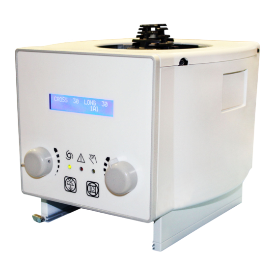
Model R 221 ACS - R 221 ACS DHHS RONT Characteristics MTR 221 ACS - MTR 221 ACS DHHS LECTRONIC YSTEM MANUALE ISTRUZIONI / INSTRUCTION MANUAL... - Page 52 Model R 221 ACS - R 221 ACS DHHS • Supply +5V from the GC007 board. • CAN Bus line with a termination jumper • Display LCD 20x2 Large letters • 2 encoders per each front panel to control knobs •...
- Page 53 Model R 221 ACS - R 221 ACS DHHS Front side not used Filter push button (default) Light push button (default) not used Left shutter, Cross (default) Right shutter, Long (default) LED1 Customed LED, controlled by system LED3 Green, collimator R in automatic mode EADY LED4...
- Page 54 Model R 221 ACS - R 221 ACS DHHS Back Side LED2 Supply + 5V present Contrast adjustment of LCD abilita la terminazione a 120 Ohm su CAN Bus To be defined To be defined Enables pull-up on IN-1 Enables pull-up on IN-2 Programming connector through E1 Renesas Programmer J3 - Serial RS232, Standard...
-
Page 55: Gc-Led-4A
Model R 221 ACS - R 221 ACS DHHS J4 - External NTC Inputs 1. - input 2. - GND J5 - Open Collector Outputs 1. - +5V 2. - output 1 (closes GND) 3. - +5V 4. - output 2 (closes GND) J6 - Supply and CAN Bus 1. - Page 56 Model R 221 ACS - R 221 ACS DHHS ONNECTORS 1. 24 V AC/DC or 12 V DC 2. 24 V AC/DC or 12 V DC 3. +5 V Fan 4. GND Fan J2 - S UPPLY AND UTPUTS 5. +5 V Laser 6.
- Page 57 Model R 221 ACS - R 221 ACS DHHS JP14 - A DDITIONAL RESISTANCE OFF: standard input ON: used to power a retro-reflective photocell JP8, JP9, JP10, JP11, JP12, JP13 - Operation mode selection OFF: Standard ON: the timer operates in the time renew mode. When the button is JP8 - T pressed the time is renewed without the LED OFF (if the LED is already IME RENEW MODE...
- Page 58 Model R 221 ACS - R 221 ACS DHHS LED 1 Power supply + 5 V REEN Indicates software version: 1 blink = standard sw 2 blinks = 3.01 sw LED 2 ELLOW 3 blinks = 5.00 sw 4 blinks = 4.00 LED 2 will stop blinking if LED 3 is ON.
- Page 59 Model R 221 ACS - R 221 ACS DHHS The timer identifies anomalies/errors/malfunctions. The outgoing messages from J7 are managed and interpreted by “intelligent board” bit = 10 ms byte: 1 bit sync (1) 8 bit data - transmission bit L..H 1 bit stop (0) Output status: 0 = output disabled...
-
Page 60: Gc 24 V Power Supply Converter
Model R 221 ACS - R 221 ACS DHHS GC 24 V Power Supply Converter Characteristics: • Input voltage Vin: 24-35 V AC +/-10%, 28-45 V DC +/-10% • Fusible: 3.15 A T standard 5x20mm Outputs: • +24Vdc / 2A •... -
Page 61: System Start-Up
Model R 221 ACS - R 221 ACS DHHS SYSTEM START-UP On system power-up, the GC007 board software performs a series of tests aimed at self- assessment. Depending on the position of the key at the back of the collimator, the automatic or manual control phase will initiate on receipt of CanBus controls. -
Page 62: Description Ofc
Model R 221 ACS - R 221 ACS DHHS BOARD CONFIGURATION Can Speed 500 kBits/s NOTE PEED SHOWN ON THE DISPLAY HAS BEEN CONFIGURED ACCORDING TO THE DIPSWITCH SETTING GC007 PCB ON THE followed by: W a i t C o m m a n d..It is possible to perform the collimator configuration by sending the CAN Bus string, or by setting it manually. -
Page 63: Updating Of Firmware
The Loader_2.1 is a Hardware + Software tool used to directly connect the USB Serial Converter to the X-Ray collimator and to con- figure X-Ray Collimator parameters accord- ing to RALCO CAN communication protocol. Bill of Material The Loader_2.1 tool requires the following items: •... -
Page 64: Installation
Loader_2.1 Application Program In order to install the Loader_2.1 Application Program, simply unzip the .rar archive provided by RALCO into the selected folder. Workflow Following the detailed workflow. MTR 221 ACS - MTR 221 ACS DHHS... -
Page 65: Hw Setup
Such file contains the Firmware to upgrade into the X-Ray Collimator. Important note: Use only.COD firmware files provided and approved by RALCO S.r.l. Any other file different from these ones can be responsible of a malfunctioning of the collimator. MTR 221 ACS - MTR 221 ACS DHHS... -
Page 66: Install
Model R 221 ACS - R 221 ACS DHHS Install Firmware Upload Complete Open the Loader_2.1.exe file and power ON the collimator. If the configuration stage has been correctly completed, the upload procedure shall start automatically. When the X-Ray Collimator upload is completed, the tool retrieves the proper status message. -
Page 67: Configuration Via Serial
ONFIGURATION VIA ERIAL NTERFACE Configuration of the collimator via serial interface is performed in Ralco with updated software; the customer will be required to load the software as described in the preceding paragraph. OTENTIOMETER OSITIONING... -
Page 68: Essage List Overview
Model R 221 ACS - R 221 ACS DHHS CAN BUS MESSAGES ESSAGE VERVIEW Message Type Description Tx_Config 0x600 Message sent to the collimator in order to set its configuration parameters. The collimator shall be in Configuration Mode. Tx_Config 0x601 Message sent to the collimator in order to read the actual value of its configuration parameters. -
Page 69: Ollimator Onfiguration
Model R 221 ACS - R 221 ACS DHHS Message Type Description Rx_Status 0x7F5 Status Message retrieved from the Collimator. Rx_Status 0x7F7 Status Message retrieved from the Collimator. Rx_Acknowledge 0x7F8 Acknowledge Message retrieved from the Collimator. Rx_Status 0x7F9 Status Message retrieved from the Collimator. Rx_Status 0x7FC Status Message retrieved from the Collimator. - Page 70 Model R 221 ACS - R 221 ACS DHHS Type DLC RTR Description sion Configure the X-Ray Collimator spectral filter wheel with the provided setting value. Tx_Con SFW_Installed : 0x00 = The X-Ray Collimator does not have the 0x600 0x05 SFW_Installed 0x00 0x00...
- Page 71 Model R 221 ACS - R 221 ACS DHHS Type DLC RTR Description sion Configure the X-Ray Collimator such that the left receptor is set according to the provided setting value. LeftReceptorType : 0x00 = The X-Ray Collimator left receptor is not installed.
- Page 72 Model R 221 ACS - R 221 ACS DHHS Type DLC RTR Description sion Configure the X-Ray Collimator fixed SID (Source Image Distance) with the provided setting value defined with bytes Tx_Con MSB_FixedSI 0x600 0x0F LSB_FixedSIDValue 0x00 0x00 0x00 0x00 0x00 [MSB_FixedSIDValue;...
- Page 73 Model R 221 ACS - R 221 ACS DHHS Type DLC RTR Description sion Configure the X-Ray Collimator such that it will automatically Tx_Con LSB_XAx MSB_YA LSB_YAxi 0x600 0x18 0x01 MSB_XAxis 0x00 0x00 retrieve offset inclinometer data values for the selected side. 1.00 (the side is the same as the lexan one) Configure the X-Ray Collimator Cross shutter manual regulation...
- Page 74 Model R 221 ACS - R 221 ACS DHHS Type DLC RTR Description sion Configure the X-Ray Collimator encoders inversion sensitivity with the provided setting value. Tx_Con 0x600 0x21 EncodersInversionSensitivity 0x00 0x00 0x00 0x00 0x00 0x00 EncodersInversionSensitivity : 25ms. (default) 1.00 EncodersInversionSensitivity eligible range of values : [0;250]ms...
- Page 75 Model R 221 ACS - R 221 ACS DHHS Type DLC RTR Description sion Configure the X-Ray Collimator analog input with the provided setting value. Tx_Con 0x600 0x29 AnalogInputUsage 0x00 0x00 0x00 0x00 0x00 0x00 AnalogInputUsage = 0x01 : the GC007 Analog Input is used for 1.00 the proximity sensor.
- Page 76 Model R 221 ACS - R 221 ACS DHHS Type DLC RTR Description sion Configure the X-Ray Collimator potentiometers with shutters Tx_Con totally closed. 0x600 0x32 SettingsPotClosed 0x00 0x00 0x00 0x00 0x00 0x00 1.00 SettingsPotOpened = 0x01 : start potentiometers configuration with totally closed shutters.
- Page 77 0x00 0x00 0x00 0x00 1.00 retreves the string "RALCO" SetFirmNameOnLCD = 0x01 : At the power on, the LCD screen retreves the string set with the 0x3B Configuration message. Configure the X-Ray Collimator message that appears on the Tx_Con LCD at the power on with the provided characters.
- Page 78 Model R 221 ACS - R 221 ACS DHHS Type DLC RTR Description sion Configure the X-Ray Collimator manual movement speed type with the provided setting value. ManMovSpeedType = 0x01 : Shutters are manually moved at a Tx_Con 0x600 0x44 ManMovSpeedType 0x00 0x00...
- Page 79 Model R 221 ACS - R 221 ACS DHHS Type DLC RTR Description sion Configure the X-Ray Collimator manual collimation with the provided setting value. Tx_Con EnableManCollimation = 0x00 : the X-Ray Collimator manual 0x600 0x4B EnableManCollimation 0x00 0x00 0x00 0x00 0x00 0x00...
- Page 80 Model R 221 ACS - R 221 ACS DHHS Type DLC RTR Description sion Configure the name of the spectral filter selected. filterNr : number of the filter for which to configure the name. Ch1…Ch6 : first bundle of Characters for setting the name of the spectral filter.
- Page 81 Model R 221 ACS - R 221 ACS DHHS Type DLC RTR Description sion Message retrieved from the collimator as response to the 0x601 Rx_Con 0x602 Data Data Data Data Data Data Data Configuration Message with the actual Value for the 1.00 configuration parameter specified by Mux.
- Page 82 Model R 221 ACS - R 221 ACS DHHS Type DLC RTR Description sion Cross Shutter Tx_Co Long Shutter Incline Value 0x7A0 Incline Command Message. 1.00 mmand [0;70°] Value [0;70°] LSB_R LSB_Left MSB_Rig LSB_Rig MSB_Rig Tx_Co MSB_LeftCr MSB_LeftLon ightLo Command message used in order to set lateral side formats for 0x7A1 LSB_LeftCrossValue LongValu...
- Page 83 Model R 221 ACS - R 221 ACS DHHS Type DLC RTR Description sion Command message used to set the shutters moving type when moevements are performed with message 0x7A0 sub D1. Tx_Co ShuttersMovingType = 0x01 : shutters are moved with constant 0x7A3 0x0B ShuttersMovingType...
- Page 84 Model R 221 ACS - R 221 ACS DHHS Type DLC RTR Description sion Command message used to set the actual optical fork step test Tx_Co status. 0x7A3 0xF1 OptForkStepTest 0x00 0x00 0x00 0x00 0x00 0x00 1.13 mmand OptForkStepTest = 0x00 : optical fork test step disabled. OptForkStepTest = 0x01 : optical fork test step enabled.
- Page 85 Model R 221 ACS - R 221 ACS DHHS Type DLC RTR Description sion Command message used to set the output frequency status messages (in msec). (default value : 0ms) MSB_MaxCross, LSB_MaxCross : Maximum Cross Opening Value. (default : 430mm) MSB_MaxLong, LSB_MaxLong : Minimum Long Opening Value.
- Page 86 Model R 221 ACS - R 221 ACS DHHS Type DLC RTR Description sion b0 : Not Used. b1 : 1 = b0 : 1 = Spectral b1 : 1 = Filter Wheel in Lateral b0 : = not posiiton SID to b0 : = used.
- Page 87 Model R 221 ACS - R 221 ACS DHHS Type DLC RTR Description sion Command message used from the ASR003 External Board in order to set the actual potentiometers voltage value. MSB_VPotStat,LSB_VPotStat = actual stative potentiometer LSB_V voltage value. MSB_VP LSB_VPo MSB_VP Tx_Co...
- Page 88 Model R 221 ACS - R 221 ACS DHHS Type DLC RTR Description sion If D0 b7 = If Format Correctio n Type (0x600 sub 0x42) set is in respect to b0 : 1 = Set the actual English Language. If D0 b7 = 0 value.
- Page 89 Model R 221 ACS - R 221 ACS DHHS Type DLC RTR Description sion Tx_Co Command message used to get the actual ARS003 External 0x7AE 0x00 0x00 0x00 0x00 0x00 0x00 0x00 0x00 1.00 mmand Board FW Version. Command message used exactly as the 0x600 Configuration message in order to set X-Ray Collimator Configuration Parameters without entering in Configuration mode.
- Page 90 Model R 221 ACS - R 221 ACS DHHS Type DLC RTR Description sion Status Message that retrieves the actual X-Ray Collimator Serial Rx_Stat LSB_S 0x7F2 0x53 0x2F 0x4E MSB_SN CSB_SN CSB_SN CSB_SN Number Set. 1.00 Note : the first 3 digits are constant (0x53 0x2F 0x43 = S/N) 0x00 = GC- LED Not Connected...
- Page 91 Model R 221 ACS - R 221 ACS DHHS Type DLC RTR Description sion EV_DSC_STOPPED : Event message retrieved from the Rx_Eve 0x7F4 0x05 StepperMotorNr 0x00 0x00 0x00 0x00 0x00 0x00 collimator when both the selected motor and the corresponding 1.13 knob stop their movement.
- Page 92 Model R 221 ACS - R 221 ACS DHHS Type DLC RTR Description sion EV_POTENZIOMETRO : Event message retrieved from the LSB_A collimator that contains the actual analogic value of the MSB_An CSB_Ana CSB_Ana Rx_Eve nalogic potentiometer connected to the indicated stepper motor. 0x7F4 0x0F StepperMotorNr...
- Page 93 Model R 221 ACS - R 221 ACS DHHS Type DLC RTR Description sion EV_ERROR : Error message retrieved from the collimator that contains the difference between the actual value retrieved by the potentiometer connected to the selected stepper motor and its MSB_Del CSB_Delt CSB_Delt...
- Page 94 Model R 221 ACS - R 221 ACS DHHS Type DLC RTR Description sion EV_ERROR : Error message retrieved from the collimator that contains the error code generated by the indicated CAN FiFo LSB_C while it is in OverRun status. MSB_CA CSB_CA CSB_CA...
- Page 95 Model R 221 ACS - R 221 ACS DHHS Type DLC RTR Description sion b0 : 1 = b0 : 1 = Error Filter while Width updating b0 : 1 = Selected. the Flash LIGHT b0 : 1 = b1 : 1 = Memory switched Differenti...
- Page 96 Model R 221 ACS - R 221 ACS DHHS Type DLC RTR Description sion b0 : 1 = Optical Fork Obscured while Cross Shutter is totally closed. b1 : 1 = Optical Fork Obscured while Long Shutter is totally closed. b2 : 1 = Spectral Filter...
- Page 97 Model R 221 ACS - R 221 ACS DHHS Type DLC RTR Description sion D0 = 0x01 - LCD Display Visualizatio n Type Standard D0 = 0x01 - Tx_Disp LCD Display Configuration Message to set-up the LCD Display Visualization layConfi 0x7C0 Not Used Not Used...
- Page 98 Model R 221 ACS - R 221 ACS DHHS Type DLC RTR Description sion b0 : 1 = Ready relay Output activation required b1 : 1 = ExpHold relay Output activation required b2 : 1 = Manual relay Output activation required.
- Page 99 Model R 221 ACS - R 221 ACS DHHS Type DLC RTR Description sion b0 : 1 = b0 : 1 = lsb_Number Ready relay Output Consecutive activation Spectral Filter required Positioning b1 : 1 = Attempts. ExpHold b1 : 1 = relay Output msb_Number activation...
- Page 100 Model R 221 ACS - R 221 ACS DHHS Type DLC RTR Description sion b0 : 1 = Ready relay Output activation required b1 : 1 = ExpHold relay Output activation required b2 : 1 = Manual relay Output activation required.
-
Page 101: Start Guide
Model R 221 ACS - R 221 ACS DHHS QUICK START GUIDE GC 007 OARD Description This collimator features an open communication CanBus connected to board GC007. CanBus messages used by the collimator are described in this Chapter C ESSAGES ;... - Page 102 Model R 221 ACS - R 221 ACS DHHS X-Ray Communicatio Scenario Collimator Messages Message Description n Protocol Description Model 0x7A3 8 0x01 0x00 0x00 0x00 0x00 0x00 0x00 Rotates the Pediatric Filter to 0x00 position 0 [Adim]. The Collimator replies with the 0x7F1 8 0x-- 0x-- 0x-- 0x00 0x-- 0x-- 0x-- 0x-- Pediatric Filter Actual Position.
-
Page 103: Inimum Filtration Requirement
Model R 221 ACS - R 221 ACS DHHS COMPLIANCE VERIFICATION INIMUM ILTRATION EQUIREMENT To indicate compliance with 21 CFR, sub-chapter J, part 1020 of Performance Standard it is necessary for the assembler to perform a series of tests. Description of test methods are illustrated in this chapter but factors, such as experience, availability of equipment and tolerance on compliance are referred directly to the Safety Standards covering Electro-medical equipment. -
Page 104: Visual Determination Of Half-Value Layer (Hvl)
Model R 221 ACS - R 221 ACS DHHS All X-ray systems, except dental X-ray systems designed for use with intraoral image receptors subjected to this section and manufactured on or after June 10, 2006. The information contained in the above table was extracted from the Code of Federal Regulations FDA 21 1020.30 (m). -
Page 105: Isual Definition Of X- Rayv
Model R 221 ACS - R 221 ACS DHHS in millimetres of aluminium obtained during the test must be greater or equal than the values listed in the above mentioned table. a) Direct the central X-ray beam perpendicular and in the center of a RAD-Check instrument. Determine the exact distance from the X-ray tube focal spot to the window of the collimator (273 mm - 10.75"). -
Page 106: Rosshair Lignment
Model R 221 ACS - R 221 ACS DHHS ROSSHAIR LIGNMENT HAPTER DJUSTMENTS PARAGRAPH ROSSHAIR LIGNMENT IGHT IELD LLUMINATION NTENSITY a) When a light field simulating the X-Ray field is used the illumination provided at 100 cm. cannot be less than: 160 lux [(21 CFR 1020.31 (d) (2) (ii)]. b) Place the Focus of the X-Ray tube at 100 cm. -
Page 107: Electromagnetic Emissions
Model R 221 ACS - R 221 ACS DHHS Electromagnetic Emissions The R 221 ACS - R 221 ACS DHHS colimator is suitable for use in the specified electromagnetic environment. The purchaser or user of the R 221 ACS - R 221 ACS DHHS should assure that it is used in an electromagnetic environment as described below: Emissions Test Compliance... -
Page 108: Electromagnetic Immunity For All Equipment And Systems
Model R 221 ACS - R 221 ACS DHHS Electromagnetic Immunity for All Equipment and Systems Collimator R 221 ACS - R 221 ACS DHHS is intended for use in the electromagnetic environmenmt specified below. The customer or the user should assure that it is used in such an environment. Immunity IEC 60601 Test Electromagnetic Environment... - Page 109 Model R 221 ACS - R 221 ACS DHHS Frequency Range and Level: RF wireless communication EQUIPMENT **Pulse Modulation: 217 Hz **Pulse Modulation: 18 Hz 1720 **Pulse Modulation: 217 Hz 1845 1970 2450 **Pulse Modulation: 217 Hz 5240 **Pulse Modulation: 217 Hz 5500 5785 MTR 221 ACS - MTR 221 ACS DHHS...
- Page 110 Model R 221 ACS - R 221 ACS DHHS COVER REMOVAL EMOVE THE SNAP FIT FRONT PANEL BY PRISING IT OFF AS SHOW IN THE PHOTOGRAPH ETACH THE FRONT PANEL CONNECTOR URN THE COLLIMATOR OVER AND REMOVE THE GUIDE SPACER FIXING SCREWS MTR 221 ACS - MTR 221 ACS DHHS OVER...
- Page 111 Model R 221 ACS - R 221 ACS DHHS GENTLY EASE THE TAPE INTO THE COLLIMATOR REMOVE THE SCREW FROM THE SNAP FIT PLATE REMOVE THE REAR PLATE EMOVE THE SNAP FIT LATERAL PANEL BY PRISING IT OFF AS SHOW IN THE PHOTOGRAPH MTR 221 ACS - MTR 221 ACS DHHS OVER...
- Page 112 Model R 221 ACS - R 221 ACS DHHS REMOVE THE COVER BY LIFTING IT OFF THE COLLIMATOR MTR 221 ACS - MTR 221 ACS DHHS OVER EMOVAL MANUALE ISTRUZIONI / INSTRUCTION MANUAL...
-
Page 113: Removal
SHOULD ANY PROBLEM ARISE REQUIRING THE NEED TO RECALIBRATE PLEASE CONTACT RALCO FOR ASSISTANCE BEFORE PROCEEDING WITH THE ADJUSTMENT ROSSHAIR DJUSTMENT • Activate the light field. • Adjust the light field to a narrow line for each pair of shutters by turning the two knobs alternately. -
Page 114: Otor Djustment
Model R 221 ACS - R 221 ACS DHHS • Tilt the base until the laser beam falls over the perpendicular bisector line on the anti-dust panel, see Fig. Laser Alignment. • Tighten the two B screws. ARNING O NOT APPLY EXCESSIVE FORCE TO THE SCREW HE LASER SHELL Fig. - Page 115 Model R 221 ACS - R 221 ACS DHHS Fig. Photocell Adjustment MTR 221 ACS - MTR 221 ACS DHHS DJUSTMENTS MANUALE ISTRUZIONI / INSTRUCTION MANUAL...
-
Page 116: Roubleshooting
The use of a faulty collimator might impair the safety of the operator and patient. Before returning the collimator to Ralco for repair, please make sure that the fault is not caused by one of the problems listed below. If the indications provided fail to solve your fault, please... - Page 117 Model R 221 ACS - R 221 ACS DHHS Green +3.3 V present In case LD3 is OFF: • check if system power supply is OK • is still NOK, check if system cable is connected correctly • if still NOK, replace GC007 (see chapter S UBSTITUTIONS •...
- Page 118 Color Function Fault Indication Action LED4 LED CONFIG Green Very slow • Incorrect or not existing blink speed • Used by Ralco Configuration data (0.05 sec) message received Medium blink speed (0.3 • Temporary correct data • Used by Ralco...
- Page 119 Model R 221 ACS - R 221 ACS DHHS LED3 Alarms 1 blink: Disconnected LED or Driver failure • check if LED is connected correctly • if still NOK, replace LED • if still NOK, replace GC-LED-4A (see chapter S UBSTITUTIONS •...
-
Page 120: Ubstitutions
The LED Substitution Kit is composed of the following components: the LED (A), and an extension cable (B), pictured in Fig. LED Substitution Kit. This Kit is designed to substitute any LED Ralco provides. Fig. LED kit Prior to replacing the LED, confirm which version of LED is installed on your collimator which will ensure the substitution is performed correctly. -
Page 121: Replacing The Previous Version Led
Model R 221 ACS - R 221 ACS DHHS • The previous version LED is connected to the board via 2 cables (red and black), see Fig. Previous Version LED below. Fig. Previous Version LED • The new LED is connected to the board via the connector, see Fig. New Version LED below. -
Page 122: Replacing The New Version Led
Model R 221 ACS - R 221 ACS DHHS Replacing the New Version LED To replace the new version LED, only part A of the Kit must be used. To substitute the LED, proceed as follows: • Disconnect supply. • Remove the cover, see Chapter C OVER EMOVAL •... -
Page 123: Led
Model R 221 ACS - R 221 ACS DHHS UBSTITUTION OF THE LECTRONIC OARD FOR The PCB Substitution Kit is composed of the following components: the board (A), an extension cable (B)* and 8 jumpers (C), pictured in opposite Fig. PCB Substitution Kit. -
Page 124: Ubstitution Of The Lectronic
Model R 221 ACS - R 221 ACS DHHS Fig. Extension Cable Connection Fig. Connector Removal UBSTITUTION OF THE LECTRONIC GC 007 OARD • Disconnect Supply. • Remove the cover to access the component, see Chapter- C OVER EMOVAL • Remove the GC LED 4A and CAN Step 4 boards by unscrewing the screws F and G. -
Page 125: Ubstitution Of Etractable Easure
Model R 221 ACS - R 221 ACS DHHS Substitution of the Electronic Board GC • Disconnect Supply. • Remove part of the cover to access the component, see Chapter- C OVER EMOVAL • Remove the 4 screws holding the electronic board. -
Page 126: Ubstitution Of The Aser
Model R 221 ACS - R 221 ACS DHHS Fig. Substitution of Retractable Tape Measure UBSTITUTION OF THE ASER • Disconnect power supply. • Remove a part of the cover, see Chap- ter- C OVER EMOVAL • Unscrew the fixing Allen screws on the upper part of the support. -
Page 127: Ubstitution Of The Irror
Model R 221 ACS - R 221 ACS DHHS UBSTITUTION OF THE IRROR • Remove the collimator cover, see Chapter - C OVER EMOVAL • Disconnect power supply. • Remove the 4 screws holding the electronic board. • Identify the cables and their position on the board, see Chapter I NSTALLATION... -
Page 128: Hotocell Substitutions
Model R 221 ACS - R 221 ACS DHHS HOTOCELL UBSTITUTIONS Cross photocell • Disconnect supply. • Remove the cover, see Chapter - C OVER EMOVAL • Close the shutters completely. • Detach the photocell connector. • Remove the photocell by unscrewing the 2 screws K. -
Page 129: Abels
Model R 221 ACS - R 221 ACS DHHS SPARE PARTS HEN ORDERING SPARE PARTS THE CUSTOMER IS REQUESTED TO SPECIFY THE COLLIMATOR MODEL AND SERIAL NUMBER HE SPARE PARTS LISTED BELOW REFER TO THE STANDARD MODEL ONLY LEASE CONSULT YOUR PERSONALIZATION PAGE TO VERIFY WHICH SPARE PARTS MAKE UP YOUR CUSTOMIZED MODEL ABELS ABEL... - Page 130 Model R 221 ACS - R 221 ACS DHHS ABEL ABEL ABEL ABEL ABEL Fig. DHHS Labels Fig. Standard Label MTR 221 ACS - MTR 221 ACS DHHS PARE ARTS MANUALE ISTRUZIONI / INSTRUCTION MANUAL...
- Page 131 Model R 221 ACS - R 221 ACS DHHS Fig. Standard and DHHS Model Labels, LED and Laser (Red Laser Line, Class 1) MTR 221 ACS - MTR 221 ACS DHHS PARE ARTS MANUALE ISTRUZIONI / INSTRUCTION MANUAL...
- Page 132 Model R 221 ACS - R 221 ACS DHHS R 221 ACS - R 221 ACS DHHS ESCRIPTION RS 596 Screw, TC M3x25mm RS 754 Right accessory guide RS 755 Left accessory guide RS 781 Key switch RS 907 RS 1012 Mounting flange RS 1120 Knob...
-
Page 133: Parts Breakdown
Model R 221 ACS - R 221 ACS DHHS Parts Breakdown MTR 221 ACS - MTR 221 ACS DHHS PARE ARTS MANUALE ISTRUZIONI / INSTRUCTION MANUAL... -
Page 134: 002 Iron Mounting Flange Spacer
Model R 221 ACS - R 221 ACS DHHS OPTIONAL ITEMS This collimator may have the following optional items; a detailed description is provided in this chapter. RO 002 Iron Mounting Flange Spacer This accessory is used for the mounting flange;... -
Page 135: 054 Square Iron Mounting Flange Spacer
• Edge contrast (if applicable), • Operation and electronic check up. RO 074 External housing and guide rails in customized color The customer can specify a collimator cover color. Ralco’s standard color is RAL9003. MTR 221 ACS - MTR 221 ACS DHHS PTIONAL... -
Page 136: 082 Glass Mirror
Model R 221 ACS - R 221 ACS DHHS RO 082 Glass Mirror Glass mirror, 0.8 mm thickness, inherent filtration 1 mm Al equivalent. With this mirror, the collimator equivalent filtration value of 2 mm Al is reduced to 1 mm Al. RO 096 Wiring Customization Customized electrical wiring. - Page 137 Model R 221 ACS - R 221 ACS DHHS ALCO RECOMMENDS FOLLOWING THE BELOW PROCEDURE DURING THE INSTALLATION OF THE COLLI MATOR EQUIPPED WITH THE SIEMENS TOP COVER TO THE X RAY TUBE HE CORRECTLY PERFORMED PROCEDURE ALLOWS THE COLLIMATOR TO ROTATE FREELY ROCEDURE 1.
-
Page 138: 210 Aluminium Acessory Guides
Model R 221 ACS - R 221 ACS DHHS RO 210 Aluminium Acessory Guides Aluminium accessory guides in RAL 9003 used to input filters or ionization chamber. RO 240 Focal-spot to skin spacer This accessory ensures a minimum safety distance (309.5 mm) between the X-ray focus and the patient. -
Page 139: 242/1 Single Laser Line To Align Collimator And Detector Center: Class 2
Model R 221 ACS - R 221 ACS DHHS RO 242/1 Single laser line to align collimator and detector center: Class 2 The collimator laser is classified as Class 2 (1 m W Fig. Laser Line - wavelength = 645 mm, +/- 10 nm); used for collimator/image receptor center alignment, see Fig. - Page 140 Model R 221 ACS - R 221 ACS DHHS • Tighten the screws. • Check the laser alignment, see Chapter- A DJUSTMENTS • Remount the cover, see Chapter- C OVER EMOVAL Classification EN 60825-1 par. 1 -5: Class 2 laser product => Red laser line. ABEL ABEL ABEL...
-
Page 141: 242/2 Two Lasers
Model R 221 ACS - R 221 ACS DHHS Fig. DHHS Model Labels, LED and Laser (Red Laser Line - optional RO 242/1) RO 242/2 Two lasers (one mounted externally) forming a crosshair to center the patient to the collimator: Class 2 Second laser which serves to center the patient using the cross projection. - Page 142 Model R 221 ACS - R 221 ACS DHHS ALIBRATION ONTROL • Draw a cross (two lines at 90°) on a sheet of paper and use this as reference. • Switch the light ON and set the sheet of paper at 1 m from the focus.
- Page 143 Model R 221 ACS - R 221 ACS DHHS • Tighten the Allen screw. • Check the laser alignment, see paragraph A DJUSTMENT • Remount the laser cover. Fig. Vertical laser Fig. Horizontal Laser Classification EN 60825-1 par. 1 -5: Class 2 laser product => Red laser line. ABEL ABEL ABEL...
- Page 144 Model R 221 ACS - R 221 ACS DHHS Fig. Standard Model Labels, LED and Laser (Red Laser Line - optional RO 242/2) Fig. DHHS Model Labels, LED and Laser (Two Red Laser Lines - optional RO 242/2) MTR 221 ACS - MTR 221 ACS DHHS PTIONAL TEMS MANUALE ISTRUZIONI / INSTRUCTION MANUAL...
-
Page 145: 253 Accessory Guide Rail Spacers In Standard Housing Color
Model R 221 ACS - R 221 ACS DHHS RO 253 Accessory guide rail spacers in standard housing color A pair of plastic rail guides complete (RAL 9003) with support (unless RO 074 is selected) designed to accommodate the ionization chamber and ensure its lateral protection. -
Page 146: 305 Additional Variable Filtration - Automatic Selection
Model R 221 ACS - R 221 ACS DHHS RO 305 Additional Variable Filtration - Automatic Selection Additional variable filtration may be added to the minimum collimator filtration in the form of an aluminium disk, 1 mm thickness, with automatic control via the electronic PCB. -
Page 147: 305/1 Additional Variable Filtration
• Board ASR003 is an extension of the radiological system, providing an interface for the col- limator to other system devices with analogical signals. • It operates via CAN BUS with a Ralco proprietary protocol. • The user end features 32 digital inputs, 8 analogue inputs and 10 relay outputs. - Page 148 • Digital inputs are optoisolated to allow connection to devices that supply output control volt- ages (typical range 12-32 V DC). • Supply: 24V DC. • Fuse: n.a. (not supplied by Ralco). Digital and Analogue Inputs Digital Input Since the input signal sometimes comes from a voltage-free contact, the board features a number of pins to which an external supply may be connected.
- Page 149 Model R 221 ACS - R 221 ACS DHHS The 10 output relays each have an NO/NC contact and may consequently be adapted to a number of different configurations. Their use depends on the software applied. This board also supplies the go-ahead to program some of the system parameters. Mechanical Installation of the External Interface Unit The external box is to be...
- Page 150 Model R 221 ACS - R 221 ACS DHHS • The other end of the cable, with the DB9 connector and 3 wires, must be connected to the CanBus interface and power supply, see Fig. 1. • Consult the electric drawing to perform a correct connection of inputs. Fig.
- Page 151 Model R 221 ACS - R 221 ACS DHHS HE WIRING DIAGRAM INCLUDED IN THIS DOCUMENT REFERS TO THE STANDARD PRODUCT T IS THE RESPONSIBILITY OF THE CUSTOMER WHO HAS REQUESTED AN ELECTRIC CUSTOMIZATION TO ENSURE THAT AN ELECTRIC DIAGRAM RELATING TO THE CUSTOMIZATION HAS BEEN PROVIDED WITH THE DOCUMENTATION HE DEVICE IS PROJECTED TO OPERATE WITH A PERMANENT POWER SUPPLY PRESENT SO THE PROCEDURE OF SWITCHING OFF THE COLLIMATOR IS NOT FORESEEN...
- Page 152 Model R 221 ACS - R 221 ACS DHHS fixed lateral SID, vertical Bucky, lateral Bucky, etc.) are to be connected to the connectors of the external board. Correct operation of the system is guaranteed if the return signals from the Bucky (if mounted) and SID Potentiometers are clean and devoid of electrical disturbances.
- Page 153 Model R 221 ACS - R 221 ACS DHHS Fig. ASR003 Board MTR 221 ACS - MTR 221 ACS DHHS PTIONAL TEMS MANUALE ISTRUZIONI / INSTRUCTION MANUAL...
- Page 154 Model R 221 ACS - R 221 ACS DHHS MTR 221 ACS - MTR 221 ACS DHHS PTIONAL TEMS MANUALE ISTRUZIONI / INSTRUCTION MANUAL...
- Page 155 Model R 221 ACS - R 221 ACS DHHS OUTPUTS All outputs are simple relay contacts (1 A 24 V DC) configured as normally open.Output relays can switch 1 A to 110 V AC or 30 V DC; do not exceed these values and provide fuses on load supply circuits.
- Page 156 Model R 221 ACS - R 221 ACS DHHS Signal Contact Description Common +V DC Filter selection 3 Filter selection 4 Common +V DC Collimator Light ON Exclusion of collimator tilt device Common +V DC Manual Mode selection Tomography Mode selection Common contacts selection (+V DC) Contact for the fixed lateral full size SID - 1 Contact for the fixed lateral full size SID - 2...
- Page 157 Model R 221 ACS - R 221 ACS DHHS Signal Contact Description IN-AN Cable shielding of potentiometer SID/ table IN-AN Potentiometer SID/Table terminal (high-level 5 V DC) IN-AN Potentiometer SID/Table slider IN-AN Potentiometer SID/Table terminal (low-level 0 V DC) IN-AN Cable shielding of potentiometer SID/Table IN-AN Cross potentiometer/table Bucky terminal (high-level 5 V DC)
- Page 158 Model R 221 ACS - R 221 ACS DHHS • The analogue signal (V DC) from the table translator potentiometer slider must increase with the decrease of the SID (as the table rises). Use a voltmeter to check this condition between contacts M91 (+) and M92 (-).
- Page 159 Model R 221 ACS - R 221 ACS DHHS Fig. Radiology System. MTR 221 ACS - MTR 221 ACS DHHS PTIONAL TEMS MANUALE ISTRUZIONI / INSTRUCTION MANUAL...
- Page 160 Model R 221 ACS - R 221 ACS DHHS Calibration Start-Up It is possible to start calibration in two manners: Fig. 1 • Press the LIGHT (C) push button and keep pressed while switching the collimator ON, see Fig. 1. •...
- Page 161 Model R 221 ACS - R 221 ACS DHHS 2. Measuring Unit - Centimetres The Encoder Cross (A) will allow to switch from CENTIMETRES to INCHES. Measuring Units centimetres Press LIGHT to confirm the setting; the next selection will be displayed: 3.
- Page 162 Model R 221 ACS - R 221 ACS DHHS 3.3. Offset Inclinometer - 90° CW WARNING 90° (CW) AKE SURE THAT THE COLLIMATOR IS ROTATED TOWARD LEFT WHILE ACQUIRING DATA OTHERWISE THE CALIBRATION WILL NOT BE VALID Inclinometer Offset 90 L X: xx Y: xx value read...
- Page 163 Model R 221 ACS - R 221 ACS DHHS 4.1. Potentiometer Input Potentiometer Input Stand Pot/Table Pot Indicate the potentiometer to be calibrated (table or stand) Press LIGHT (C) to confirm the setting. 4.1.1. Calibration of Vertical SID - Table Down Indications displayed for the calibration of the table analogue signal require the table to be lowered: Move Table Down...
- Page 164 Model R 221 ACS - R 221 ACS DHHS 4.1.2. Calibration of Vertical SID - Stand All Up Move Stand Full Up xxx pts The display will provide calibration indications for the stand analogue signal, requiring the stand be raised to a higher position. The second line of the display shows the digitized voltage value generated by the stand potentiometer.
- Page 165 Model R 221 ACS - R 221 ACS DHHS 5. Right Lateral SID Measure The Encoder Cross (A) will allow to switch between DISCRETE SID, CAN or POTENTIOMETER. Press LIGHT (C) to confirm the setting; the next selection will be displayed: Right Lateral SID DISCRETE/CAN/POTENTIOMETER •...
- Page 166 Model R 221 ACS - R 221 ACS DHHS • M . SID Minimum distance from a surface of image receptor to the film is to be set up. Min.Left Pot. SID: nnn ... cm nnn - (value read by potentiometer). •...
- Page 167 Model R 221 ACS - R 221 ACS DHHS • FIXED FORMATS: 5 fixed formats are selected. • D IGITAL ORMAT The display will read indications to enter the fixed measures of lateral SID. It is possible to connect, to the external board ASR003, the inputs (max 5) that allow to enter the fixed formats in the automatic mode.
- Page 168 Model R 221 ACS - R 221 ACS DHHS 9. Left Lateral Receptor The type of lateral receptor (left) installed with the system must be selected. The Encoder Cross (A) will allow to switch between BUCKY, CAN, NO. Left Lateral Receptor NO/BUCKY/CAN •...
- Page 169 Model R 221 ACS - R 221 ACS DHHS 13. Setting of SID Horizontal # 4 Horiz. SID Meas. # 4 xxx cm The Encoder Cross (A) will allow to enter the measurements from 25 min to 300 cm max. Press LIGHT (C) to confirm the setting.
- Page 170 Model R 221 ACS - R 221 ACS DHHS 18. Calibration of Vertical SID Limits - maximum The display will show indications of the maximum Vertical SID value accepted by the collimator. Vertical SID Max. xxx cm The Encoder Cross (A) will allow to enter the measurements from 50 cm min to 300 cm max. Press LIGHT (C) to confirm the setting;...
- Page 171 Model R 221 ACS - R 221 ACS DHHS 21. Vertical Bucky Cassettes, Calibration Table Bucky Cal. Quick system starts with calibration type. The Encoder Cross (A) will allow to switch from Quick to Full calibration. Press LIGHT (C) to confirm the setting. To cancel the procedure press FILTER (D).
- Page 172 Model R 221 ACS - R 221 ACS DHHS 22. Calibration of Left Lateral Bucky Cassette Left Bucky Cal. Quick system starts with calibration type. The Encoder Cross (A) will allow to switch from Quick to Full calibration. Press LIGHT (C) to confirm the setting. To cancel the procedure press FILTER (D).
- Page 173 Model R 221 ACS - R 221 ACS DHHS 23. Calibration of Right Lateral Bucky Cassette Right Bucky Cal. Quick system starts with calibration type. The Encoder Cross (A) will allow to switch from Quick to Full calibration. Press LIGHT to confirm the setting. To cancel the procedure press FILTER (D).
-
Page 174: 329 Internal Proximity Sensor
Model R 221 ACS - R 221 ACS DHHS RO 329 Internal Proximity Sensor A proximity sensor is a sensor able to detect the minimum distance to a patient without any physical contact, thereby avoiding the risk of collision. The proximity sensor emits an inferred beam and register a return signal if utilized correctly. The minimum distance that this sensor detects is 30 cm. - Page 175 Model R 221 ACS - R 221 ACS DHHS Calibration The two switches on the sensor front serve as reference Sensor Calibration • Rotate the Light/Dark switch to LIGHT ON to activate the sensor when the object is in measuring range. •...
-
Page 176: 330 Connecting Cable Extension
Model R 221 ACS - R 221 ACS DHHS RO 330 Connecting cable extension Connecting cable extension; Longer cable is provided for your system. MTR 221 ACS - MTR 221 ACS DHHS PTIONAL TEMS MANUALE ISTRUZIONI / INSTRUCTION MANUAL... -
Page 177: 332/A Resin Rotating Mounting Flange
Model R 221 ACS - R 221 ACS DHHS RO 332/A Resin Rotating Mounting Flange Resin rotating mounting flange with fixing screws: • 15 mm thickness • +/- 90° detent • 140 mm diameter Please refer to the chapter INSTALLATION in this Instruction Manual for the correct flange/collimator mounting instructions. -
Page 178: 344 Accessory Guide Rail Spacers With Reinforced Support
Model R 221 ACS - R 221 ACS DHHS RO 344 Accessory guide rail spacers with reinforced support Pair of plastic rail guides (RAL 9003) on metal support designed to accommodate the ionization chamber and allow the insertion of relative filter (153 mm +/- 0.5). RO 356 Shutter position verified by potentiometer Supplementary safety device to ensure correct positioning of shutters. -
Page 179: 409 Resin Rotating Mounting Flange
Model R 221 ACS - R 221 ACS DHHS RO 409 Resin Rotating Mounting Flange Resin rotating mounting flange milled to form a square: • 20 mm thickness • +/- 0° detent • 140 mm diameter Option includes three (3) iron mounting flange spacers also milled to form a square: 1.5 mm thickness. -
Page 180: 442 Resin Rotating Mounting Flange
Model R 221 ACS - R 221 ACS DHHS RO 442 Resin Rotating Mounting Flange Resin rotating mounting flange: • 20 mm thickness • +/- 90° detent • 140 mm diameter Please refer to the chapter INSTALLATION in this Instruction Manual for the correct flange/collimator mounting instructions. -
Page 181: 445 Metal Rotating Mounting Flange
Model R 221 ACS - R 221 ACS DHHS RO 445 Metal Rotating Mounting Flange Metal rotating mounting flange: • 20 mm thickness • +/- 90° mechanical stop • 140 mm diameter Please refer to the chapter INSTALLATION in this Instruction Manual for the correct flange/ collimator mounting instructions. -
Page 182: 456 Metal Rotating Mounting Flange
Model R 221 ACS - R 221 ACS DHHS RO 456 Metal Rotating Mounting Flange Metal rotating mounting flange: • 20 mm thickness • +/- 90° with mechanical stop • 136 mm diameter Please refer to section RO 492 Adjustable Top-Cover Bracket in this chapter of the Instruction Manual for the correct flange/collimator mounting instructions.. - Page 183 Model R 221 ACS - R 221 ACS DHHS • Remove the rear cover by unscrewing the four screws A. • The locking screws are marked by a red label. • Unscrew the four locking screws B to release the shutter movement. •...
-
Page 184: 484 Infrared Remote Control Box
• Release the format push button on the remote control.The new format is automatically stored in permanent memory. CAN Bus messages: The controls are standard commands of Ralco’s protocol: 0x7A0 controls the 4 shutters simultaneously in 1/10 mm. 0x7A4 controls one shutter at a time (1-4), or the filter motor (5), etc. -
Page 185: 489 Resin Rotating Mounting Flange
Model R 221 ACS - R 221 ACS DHHS id=7AE dlc=8 D0=0x02 D1 powers up laser D1 = 0x00 switches the laser OFF D1 = 0x01 switches the laser ON (maximum 60 seconds) RO 489 Resin Rotating Mounting Flange Resin rotating mounting flange: •... -
Page 186: 490 Metal Rotating Mounting Flange
Model R 221 ACS - R 221 ACS DHHS RO 490 Metal Rotating Mounting Flange Metal rotating mounting flange with countersunk mounts: • 18 mm thickness • +/- 90° with mechanical stop • 140 mm diameter Please refer to section RO 492 Adjustable Top-Cover Bracket in this chapter of the Instruction Manual for the correct flange/ collimator mounting instructions. - Page 187 Model R 221 ACS - R 221 ACS DHHS Installation UBE COMPATIBILITY 1. Using the dimensions in Fig. Tube Compatibility below, ensure the near port shutters of the collimator are placed in the X-Ray tube port without interference. 2. The distance between the X-Ray tube focus and the flange mounting plane (collimator upper plate) must be: 80 mm (3.14"), tolerance +/- 1 mm (0.04 “).
- Page 188 Model R 221 ACS - R 221 ACS DHHS 3. Carefully remove the collimator and the mounting flange (if purchased) from their packaging. 4. Use the X-Ray tube housing datasheet to determine the distance (A) from the focal spot to the X-Ray tube port, see Fig. Collimator Installation.
- Page 189 X-Ray tube manufacturer. When in doubt please contact X-ray tube manufacturer and/or Ralco. Fig. Flange Installation *illustrative purpose only Fig. Mounting Flange *illustrative purpose only...
-
Page 190: Alignment Device
X-Ray beam. All Ralco collimators are aligned on our test bench utilizing specific references/values for our X-Ray tube focus, detector and Source to Image Detector Distance (SID). The customer must know and verify all known variables which may influence the X-Ray tube focus and collimator alignment. -
Page 191: Mounting The Collimator To The Flange
Model R 221 ACS - R 221 ACS DHHS Mounting the Collimator to the Flange HE MOUNTING FLANGE PROVIDED IF PURCHASED WITH THE COLLIMATOR IS SUBJECTED TO TESTING PURSUANT TO ALL APPLICABLE STANDARDS EN60601. OUNTING RACKET ABS CONFORM TO ARNINGS URSUANT TO APPLICABLE STANDARDS ALCO HAS TESTED THE COLLIMATOR AND FLANGE APPLYING STATIC LOADS... - Page 192 *illustrative purpose only 7. The collimator should be coupled to the flange firmly. If the collimator is loose, please repeat the above mounting instructions, and if issues persist, please contact Ralco. MTR 221 ACS - MTR 221 ACS DHHS PTIONAL...
-
Page 193: 493 Dual Energy Additional Variable Filtration
4. Once the collimator is mounted, if not already, return the collimator/tube head to the intended use position. Rotate and/or gently pull the collimator to ensure correct coupling. 5. If the collimator is loose, something is incorrect. Repeat above mounting instructions, and if issues persist, please contact Ralco. Fig. Correct Overlap Fig. Incorrect Overlap RO 493 Dual Energy Additional Variable Filtration This accessory allows extremely fast filter switching (200 ms) per 90°... -
Page 194: 494 Customized Additional Variable Filtration
Model R 221 ACS - R 221 ACS DHHS RO 494 Customized Additional Variable Filtration This option allows our customer to specify a type of filtration. It is possible to assembled up to 3 different filters. RO 495 Camera assembled internally for patient monitoring An IP ethernet interface is a type of digital camera commonly employed for surveillance, and which, unlike analog closed circuit television (CCTV) cameras, can send and receive data via a computer network and the Internet. - Page 195 Model R 221 ACS - R 221 ACS DHHS • Unscrew the 4 screws placed on the rails. MTR 221 ACS - MTR 221 ACS DHHS PTIONAL TEMS MANUALE ISTRUZIONI / INSTRUCTION MANUAL...
- Page 196 Model R 221 ACS - R 221 ACS DHHS • Remove carefully the snap-on front panel and detach the connectors: A for the push button B for the front panel LED (if present). MTR 221 ACS - MTR 221 ACS DHHS PTIONAL TEMS MANUALE ISTRUZIONI / INSTRUCTION MANUAL...
- Page 197 Model R 221 ACS - R 221 ACS DHHS • Remove the lower cover. • Remove the 2 lateral covers, if necessary. • Remove the video camera with its support by unscrewing the fixing screws (C). • Detach the connectors from the video cam- era, as shown in the photos.
- Page 198 Model R 221 ACS - R 221 ACS DHHS • Remount the video camera with its support by connecting the connectors and then fixing the support to the collimator housing. • The video camera can be adjusted vertically (C.1) or be tilted (C.2) whenever it is neces- sary.
- Page 199 Model R 221 ACS - R 221 ACS DHHS HE VIDEO CAMERA IS ALREADY WELL FOCUSED IN THE FACTORY LEASE FOLLOW THE BELOW PROCEDURE TO READJUST THE FOCUS • If necessary, loosen the 2 screws (D) and rotate the whole video camera to calibrate it. •...
-
Page 200: 496 Software Customization
Model R 221 ACS - R 221 ACS DHHS • Loosen the screw F and adjust the video camera inclination, if necessary. • Tighten the screws E and F. • Remount the collimator cover in reverse order. RO 496 Software Customization Software that is developed according to the customer particular preferences, expectations and needs. -
Page 201: 525 Customized Knob Design
Model R 221 ACS - R 221 ACS DHHS RO 525 Customized Knob design The customer can specify the knob design. RO 526 Semiautomatic mode (front panel with push buttons included) This option allows the customer to control the collimator in the semi-automatic mode through customized software and the front panel. -
Page 202: Configuration Procedure
Model R 221 ACS - R 221 ACS DHHS • Choose the menu which must be configured. • Turn the right knob clockwise to switch from NO to YES. • Confirm with LIGHT (C) push button to get into the submenu. •... - Page 203 Model R 221 ACS - R 221 ACS DHHS Lamp Button Enable Enable/Disable Knob Lamp Time 10 sec *from 10 to 120 sec 0x7F0 Sending Time 200 ms *from 0 to 2000 ms Unit measure cm/inch Show SID Yes/No Filter Type 1 mm Al/2 mm Al/0.3 mm Cu/ 0.5 mm Ag Inclinometer Yes/No...
- Page 204 Model R 221 ACS - R 221 ACS DHHS Vertical SID CAN/Fixed/Differential/Single Vert. SID Poten. Input Stand/Table/No DFT Sx 0 cm *from 0 to 15 cm DFT Dx 0 cm *from 0 to 15 cm Vertical Receptor CAN/Bucky/No/ATS/Fixed Fixed SID 100 cm *from 25 to 300 cm Min SID...
- Page 205 Model R 221 ACS - R 221 ACS DHHS Correction type % on APERT/CM on SID Cross Correction +0.0 % *from -10.0% to +10.0% Long Correction +0.0 % *from -10.0% to +10.0% Display Selection CARESTREAM/FREE/SEDECAL/STANDARD CAN Protocol GMM/CARESTREAM/SEDECAL/STANDARD Command Address 0x7A0 Potent.
- Page 206 Model R 221 ACS - R 221 ACS DHHS Potentiometer open LAMP = START Potentiometer close LAMP = START Display ASR003 val. LAMP = START Analog Calibration Confirm? --> NO • Turn the right knob clockwise to switch from NO to YES. •...
- Page 207 Model R 221 ACS - R 221 ACS DHHS Lower 50 cm POT. Value Error! Set stand to 100 cm Focus-Table xxx pts Min. Right Pot SID: 80 cm *from 25 to 300 cm Max. Right Pot SID: 250 cm *from 25 to 300 cm Min.
- Page 208 Model R 221 ACS - R 221 ACS DHHS Set Number of Right cassette xxx Cross 1D Cm 13: Long 1D Cm 13: End of Calibration Press LAMP to RESET Shutter Calibration Confirm? --> NO • Turn the right knob clockwise to switch from NO to YES. •...
- Page 209 Model R 221 ACS - R 221 ACS DHHS HE POTENTIOMETER VALUE DIFFERENCE MUST BE AT LEAST STEPS OTHERWISE THE SOFTWARE GIVES ERROR MESSAGE CROSS 300 mm P: xxx CROSS 240 mm P: xxx CROSS 130 mm P: xxx CROSS 000 mm P: xxx LONG Manual Calibr.
- Page 210 Model R 221 ACS - R 221 ACS DHHS Serial Number Confirm? --> NO • Turn the right knob clockwise to switch from NO to YES. • Confirm with LIGHT (C) push button to get into the submenu. Serial Number 45555 •...
-
Page 211: 530 Resin Rotating Mounting Flange
Model R 221 ACS - R 221 ACS DHHS RO 530 Resin Rotating Mounting Flange Resin rotating mounting flange: • 17 mm thickness • 0° detent • 140 mm diameter Please refer to the chapter INSTALLATION in this Instruction Manual for the correct flange/collimator mounting instructions. - Page 212 Model R 221 ACS - R 221 ACS DHHS Functionality All touch screen applications for a normal use are included in a single page.The display, however, has been designed to add additional pages for future requests.The icon view on the display adapts accordingly to the collimator inclination (vertical/lateral).
- Page 213 Model R 221 ACS - R 221 ACS DHHS Electrical connection MTR 221 ACS - MTR 221 ACS DHHS PTIONAL TEMS MANUALE ISTRUZIONI / INSTRUCTION MANUAL...
- Page 214 Model R 221 ACS - R 221 ACS DHHS MTR 221 ACS - MTR 221 ACS DHHS PTIONAL TEMS MANUALE ISTRUZIONI / INSTRUCTION MANUAL...
- Page 215 Model R 221 ACS - R 221 ACS DHHS MTR 221 ACS - MTR 221 ACS DHHS PTIONAL TEMS MANUALE ISTRUZIONI / INSTRUCTION MANUAL...
- Page 216 Model R 221 ACS - R 221 ACS DHHS MTR 221 ACS - MTR 221 ACS DHHS PTIONAL TEMS MANUALE ISTRUZIONI / INSTRUCTION MANUAL...
- Page 217 Model R 221 ACS - R 221 ACS DHHS MTR 221 ACS - MTR 221 ACS DHHS PTIONAL TEMS MANUALE ISTRUZIONI / INSTRUCTION MANUAL...
- Page 218 Model R 221 ACS - R 221 ACS DHHS EMC C OMPLIANCE Electromagnetic Emissions The R 221 ACS - R 221 ACS DHHS colimator is suitable for use in the specified electromagnetic environment. The purchaser or user of the R 221 ACS - R 221 ACS DHHS should assure that it is used in an electromagnetic environment as described below: Emissions Test Compliance...
- Page 219 Model R 221 ACS - R 221 ACS DHHS Electromagnetic Immunity The R 221 ACS - R 221 ACS DHHS collimator is intended for use in the electromagnetic environment specified below. The customer or the user of the collimator should assure that it is used in such an environment. Immunity Test IEC 60601 Test Complian...
-
Page 220: 556 Measuring Tape Removal
Model R 221 ACS - R 221 ACS DHHS Recommended Separation Distances for Non-Life Supporting Equipment Collimator R 221 ACS - R 221 ACS DHHS is intended for use in an electromagnetic environment in which radiated RF disturbances are controlled. The customer or the user of the collimator can help prevent electromagnetic interference by maintaining a minimum distance between portable and mobile RF communications equipment (transmitters) and the collimator as recommended below, according to the maximum output power of the communications equipment. -
Page 221: 582 Metal Fixed Mounting Flange
Model R 221 ACS - R 221 ACS DHHS RO 582 Metal Fixed Mounting Flange Metal fixed mounting flange: • 16 mm thickness • 136 mm diameter Please refer to section RO 492 Adjustable Top-Cover Bracket in this chapter of the Instruction Manual for the correct flange/ collimator mounting instructions. -
Page 222: 587/1 Two Lasers Forming A Single Line At 1- Meter Sid: Class 1
Model R 221 ACS - R 221 ACS DHHS RO 587/1 Two lasers forming a single line at 1-meter SID: Class 1 The collimator has two lasers which serve for the optical definition of the prefixed SID. The lasers are mounted behind the front panel and they are classified as Class 1 (1 m W - wavelength = 645 mm, +/- 10 nm). - Page 223 Model R 221 ACS - R 221 ACS DHHS • Shift the laser system by loosening the two C screws holding the laser system base to the beam limiting device front plate. • Move the base until the laser beam falls over the perpendicular bisector line on the anti-dust panel, see Fig.
-
Page 224: 587/2 Two Lasers
Model R 221 ACS - R 221 ACS DHHS RO 587/2 Two lasers (one mounted externally) forming a crosshair to center the patient to the collimator: Class 1 Second laser which serves to center the patient using the cross projection. The collimator lasers are classified as Class 1 (1 m W - wavelength = 645 mm, +/- 10 nm) and are used for... - Page 225 The Laser Substitution Kit is composed of the following components: the lase (A), the extension cable (B) and the laser label (C) pictured below in Fig. Laser Substitution Kit. This Kit is designed to substitute any laser Ralco provides. Fig. Laser Substitution Kit Prior to replacing the laser, confirm which version of laser is installed on your collimator which will ensure the substitution is performed correctly.
- Page 226 Model R 221 ACS - R 221 ACS DHHS • The new laser is connected to the board via the connector, see Fig. New Laser Version below. Fig. New Laser Version Replacing the Previous Laser Version To replace the previous version of laser, all components of the Laser Substitution Kit (RS 2589) (A, B and C) must be used.
-
Page 227: 597 Asymmetric Longitudinal And Transversal Shutters
Model R 221 ACS - R 221 ACS DHHS Classification EN 60825-1 par. 1 -5: Class 1 laser product => Red laser line. ABEL ABEL ABEL ABEL Fig. Standard Model Labels, LED and Laser (Red Laser Line, class 1) RO 597 Asymmetric longitudinal and transversal shutters This option has been designed to control the shutters independently (Stitching mode). - Page 228 Model R 221 ACS - R 221 ACS DHHS Installation ARNINGS HE COLLIMATOR MUST BE INSTALLED TO THE RAY TUBE THROUGH A MOUNTING FLANGE ALCO PROVIDES VARIOUS FLANGE OPTIONS WHICH MAY NOT BE INTER CHANGEABLE NLY FLANGES PROVIDED WITH THE COLLIMATOR MAY BE UTILIZED HE END USER MAY INSTALL THEIR OWN FLANGE HOWEVER...
- Page 229 Model R 221 ACS - R 221 ACS DHHS 3. Carefully remove the collimator and the mounting flange from their packaging. 4. Use the X-Ray tube housing datasheet to determine the distance (A) from the focal spot to the X-Ray tube port, see Fig. Collimator Installation.
- Page 230 X-Ray tube manufacturer. When in doubt please contact X-Ray tube manufacturer and/or Ralco. Fig. Flange Installation *illustrative purpose only Fig. Mounting Flange *illustrative purpose only...
- Page 231 X-Ray beam. All Ralco collimators are aligned on our test bench utilizing specific references/values for our X-Ray tube focus, detector and Source to Image Detector Distance (SID). The customer must know and verify all known variables which may influence the X-Ray tube focus and collimator alignment.
- Page 232 Model R 221 ACS - R 221 ACS DHHS Mounting the Collimator to the Resin Flange (RO 610 or RO 619) HE MOUNTING FLANGE PROVIDED IF PURCHASED WITH THE COLLIMATOR IS SUBJECTED TO TESTING PURSUANT TO ALL APPLICABLE STANDARDS EN60601. OUNTING RACKET ABS CONFORM TO...
- Page 233 Model R 221 ACS - R 221 ACS DHHS 1. Prepare the collimator to be installed by unscrewing the 4 hexagonal socket screws until the four tabs are completely withdrawn form the collimator top mounting plane, see Fig. 4 Mounting Screws. 2.
- Page 234 Bracket. 5. If you are not able to respect the turns some- thing is incorrect, repeat above instructions, if issues persist, please contact Ralco. 6. Ensure the microswitch is completely engaged by tightening the set screw, see Fig. Microswitch.
- Page 235 Model R 221 ACS - R 221 ACS DHHS ARNINGS T IS THE RESPONSIBILITY OF THE SYSTEM MANUFACTURER TO ENSURE AND MITIGATE ANY DANGEROUS CONDITIONS WHICH MAY OCCUR DUE TO THE DYNAMIC FORCES CREATED BY THE SYSTEM HE END USER MUST PERFORM A SYSTEMATIC AND STRUCTURAL ANALYSIS DURING THE INSTALLATION AND USUAL MAINTENANCE HOULD ANY DAMAGE TO THE COLLIMATOR OR FLANGE OCCUR A RISK ANALYSIS AND DAMAGE ASSESSMENT NEEDS TO BE CONDUCTED IMMEDIATELY...
- Page 236 *illustrative purpose only 7. The collimator should be coupled to the flange firmly. If the collimator is loose, please repeat the above mounting instructions, and if issues persist, please contact Ralco. Verification of Correct Installation ARNING T IS THE DUTY OF THE INSTALLER TO ENSURE NO RISK OF THE COLLIMATOR...
-
Page 237: 619 Resin Rotating Mounting Flange With Position Indicator
Model R 221 ACS - R 221 ACS DHHS Fig. Incorrect Overlap Fig. Correct Overlap RO 619 Resin Rotating Mounting Flange with Position Indicator This accessory is a part of the position control system designed to indicate the collimator 0° position (+/- 3°) through a microswitch. -
Page 238: Maintenance
ECOMMENDED AINTENANCE ROGRAM Ralco suggests a yearly servicing program, however shorter intervals are advisable when the collimator is subject to heavy workloads. • Re-calibration of the collimator will be necessary whenever the X-ray tube is changed or at each substitution of the source light (lamp or LED, if assembled) used to simulate the light field. - Page 239 Model R 221 ACS - R 221 ACS DHHS • Calibration procedures (if provided) must be performed as described in this manual. • Check once a week that the screws and tabs which serve to secure the collimator to the flange/tube adapter are correctly tightened.
-
Page 240: General Warranty
In the event the collimator needs to be repaired at Ralco, you will be provided with a RMA (Return Merchandise Authorization) number as your consent to the return. If a product is returned to Ralco without a RMA or without a description of the problem, the customer will incur a €100 processing fee. -
Page 241: End Of Life Disposal
Should this prove impossible, return the collimator to Ralco at the purchaser's expense and Ralco will undertake its correct disposal. If you are replacing the unit with new equipment, you may return the old collimator to Ralco. Please contact us if you require further information. -
Page 242: Safety /Responsibility
Directive 2007/47/CE para.10 -Legislative Decree n° 46 para.10 Ralco shall not be held responsible when instructions provided in the present manual are not complied with. Ralco shall not be held responsible if the collimator relates to one or several of the following instances: •... -
Page 243: Residual Risks
Model R 221 ACS - R 221 ACS DHHS ARNINGS NFORMATION REGARDING ACCIDENTS THAT HAVE OCCURRED WHILE USING THE RADIOLOGICAL COLLIMATOR MUST BE REPORTED IMMEDIATELY TO ALCO SRL ESIDUAL ISKS The collimator has been constructed to current standards to meet the safety requisites of directive 2007/47/CE . - Page 244 Directive 2007/47/CE states that accidents (such as death or grievous injury to a patient) that involve the collimator described herein, must be reported to the Ministry of Health and to the Manufacturer. The present form is provided to report to Ralco srl post-free. Date:...
Need help?
Do you have a question about the R 221/A DHHS and is the answer not in the manual?
Questions and answers