Table of Contents
Advertisement
®
™
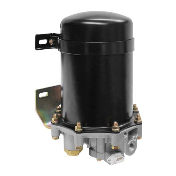
Bendix
AD-9
Air Dryer
END COVER
CHECK
VALVE
DELIVERY PORT
ASSEMBLY
EXTENDED PURGE AD-9
FIGURE 1 - AD-9
™
AIR DRYER MODELS
DESCRIPTION
The function of the AD-9
air system contaminants in solid, liquid and vapor form before
they enter the brake system. It provides clean, dry air to the
components of the brake system which increases the life of
the system and reduces maintenance costs. Daily manual
draining of the reservoirs is eliminated.
™
The AD-9
air dryer consists of a desiccant cartridge and a
die cast aluminum end cover secured to a cylindrical steel
outer shell with eight cap screws and nuts. The end cover
contains a check valve assembly, a safety valve, three
threaded air connections and the purge valve housing
assembly. The removable purge valve housing assembly
incorporates a purge valve mechanism and a turbo charger
cut-off feature that is designed to prevent loss of engine
"turbo" boost pressure during the purge cycle of the AD-9
SUPPLY
PORT
WIRING HARNESS
CONNECTION
™
AIR DRYER
™
air dryer is to collect and remove
OUTER
SHELL
END COVER
CONTROL
PORT
CHECK
VALVE
ASSEMBLY
DELIVERY PORT
air dryer. For ease of serviceability, the desiccant cartridge
and discharge check valve assembly are screw in type. The
purge valve housing assembly, which includes the heater
and thermostat assembly, and the discharge check valve
assembly, is serviceable from the exterior of the air dryer,
while servicing the screw-in desiccant cartridge requires
removal of the air dryer assembly from the vehicle.
The AD-9
™
connections and each is identified as follows:
Port l.D.
CON 4 ............... Control Port
SUP 11 ............. Supply Port (air in).
DEL 2 ............... Delivery Port (air out).
™
WIRING HARNESS
CONNECTION
™
STANDARD AD-9
AIR DRYER
air dryer has three female pipe thread air
Function/Connection
(purge valve control and turbo cut-off).
OUTER
SHELL
CONTROL
PORT
SUPPLY
PORT
1
Advertisement
Table of Contents

Related Manuals for BENDIX AD-9 AIR DRYER


Summary of Contents for BENDIX AD-9 AIR DRYER
- Page 1 ® ™ Bendix AD-9 Air Dryer OUTER OUTER SHELL SHELL END COVER END COVER CONTROL PORT CONTROL PORT CHECK VALVE SUPPLY ASSEMBLY SUPPLY PORT PORT CHECK DELIVERY PORT WIRING HARNESS VALVE WIRING HARNESS CONNECTION DELIVERY PORT ASSEMBLY CONNECTION ™ ™...
-
Page 2: Air Dryer Charge Cycle
CHECK ORIFICE VALVE DESICCANT CARTRIDGE DESICCANT PURGE VOLUME SEPARATOR CONTROL PORT GOVERNOR COMPRESSOR ← ← ← ← ← CHECK ENGINE SUPPLY VALVE TURBO PORT ASSEMBLY RESERVOIR DELIVERY PORT SUMP PURGE HEATER VALVE EXHAUST ELEMENT ™ FIGURE 2 - AD-9 AIR DRYER CHARGE CYCLE ™... -
Page 3: Turbo Cut-Off Feature
CHECK VALVE ORIFICE DESICCANT CARTRIDGE DESICCANT PURGE VOLUME SEPARATOR CONTROL PORT GOVERNOR COMPRESSOR ENGINE CHECK SUPPLY TURBO VALVE PORT ASSEMBLY RESERVOIR DELIVERY PORT TURBO SUMP PURGE CUTOFF HEATER VALVE PISTON EXHAUST ELEMENT ™ FIGURE 3 - AD-9 AIR DRYER PURGE CYCLE ™... -
Page 4: Preventive Maintenance
UPPER UPPER BRACKET BRACKET STRAP DESICCANT CARTRIDGE DESICCANT HOUSING LOWER SEPARATOR BRACKET SUPPLY PORT CONTROL PORT PURGE TURBO SUPPLY VALVE CUTOFF PORT CHECK PISTON DISCHARGE VALVE EXHAUST LINE ASSEMBLY CHECK VALVE ASSEMBLY TURBO ™ FIGURE 4 - AD-9 AIR DRYER TURBO CUTOFF CUTOFF PURGE VALVE PISTON... -
Page 5: Operation & Leakage Tests
and should not be considered as an indication that the dryer is not performing properly. Note: A small amount of oil in the system may be normal LOWER and should not, in itself, be considered a reason to ™ AD-9 MOUNTING AIR DRYER replace the desiccant;... - Page 6 When rebuilding or replacing components of the air dryer Always wear safety glasses. use only genuine Bendix parts. For ease in servicing the 2. Stop the engine and remove ignition key when AD-9 ™...
-
Page 7: Air Dryer Assembly & Parts List
COVER ITEM DESCRIPTION O-RING PURGE VALVE GUIDE 1/4" TAPPING SCREW SHOULDER BOLT O-RING O-RING - (NOT USED ON DLU MODELS) O-RING PURGE VALVE ASSEMBLY (COMPLETE) PURGE VALVE HOUSING HARD SEAT PURGE PISTON PURGE VALVE SAFETY VALVE SPRING QUAD-RING DELIVERY CHECK VALVE ASSEMBLY 3/8"... -
Page 8: Disassembly
™ Caution: While performing service on the AD-9 8. Use only genuine Bendix ® replacement parts, dryer, it is not recommended that a clamping device components and kits. Replacement hardware, (vise, C-clamp, etc.) be used to hold any die cast... -
Page 9: Cleaning And Inspection
4. Remove the remaining six 3/8" cap screws (16), lock the bore of the purge valve housing. Insert the purge nuts (19) and twelve special washers (17) that secure piston (10) into the I.D. of the return spring. Place the end cover to the housing (24). Separate the end cover the purge valve guide (2) onto the shoulder bolt (4) and desiccant cartridge (22) from the housing (24). -
Page 10: Installation
“bypass” the air accessory responsible for 2. Tighten the 5/16" X 4-1/2" hex cap screw (25) and nut the high air usage. Consult your local authorized Bendix (28) on the upper mounting bracket saddle (27) and strap parts outlet or sales representative for additional (26). -
Page 11: Vehicle Preparation
(supply) a compressor which has a rated displacement exceeding reservoir as possible. 17 CFM that an authorized Bendix parts outlet or Bendix ™ 3. Do not locate the AD-9 air dryer near heat producing marketing representative be contacted for assistance. -
Page 12: Discharge Line
CONTROL (HIDDEN) SUPPLY GOVERNOR UNLOADER PORT DELIVERY COMPRESSOR RESERVOIR SAFETY VALVE TO RESERVOIR 10 AMP - 12V 5 AMP - 24V FUSE 14 GA WIRE TO IGNITION & GROUND FIGURE 11 - AD-9 ™ AIR DRYER CHARGE CYCLE CONNECTING THE AIR LINES position the unit for ease of installation. - Page 13 AD-9 ™ air dryer will not cycle excessively. (A) Total air system leakage (See Bendix publication BW-5057 “Air Brake Handbook”). (B) Compressor unloader mechanism. (C) Governor. (D) Drain cock and safety valve in first (supply) reservoir.
-
Page 14: Troubleshooting
AD-9 ™ AIR DRYER TROUBLESHOOTING CHART REMEDY SYMPTOMS CAUSE A. Excessive system 1. Dryer is constantly A. If leakage IS SHOWN on gauges test for leakage. IMPORTANT: “cycling” or purging. excessive service brake system leakage. Note whether air Dryer purges frequently Allowable leakage: pressure loss is shown (every 4 minutes or less... - Page 15 ™ AD-9 AIR DRYER TROUBLESHOOTING CHART REMEDY SYMPTOMS CAUSE 1. Test fittings, hoses, lines and connections. Apply soap solution to detect excessive leakage. Tighten or replace as needed then repeat the air dryer charge-purge cycle and observe the gauge installed in the supply reservoir.
- Page 16 Check Valve Feed Back Line Typical Drop-In Air Dryer End Cover When installing a Bendix Drop-In air dryer in a system equipped with a Holset E or QE compressor, remove the Holset ECON valve along with its feed back and governor control line.
- Page 17 Consult your local authorized Bendix parts outlet or sales representative for additional information. leakage from fittings, connections, lines, chambers or valves, etc.
- Page 18 If the purge time is consistently less than the minimum, an accessory by-pass system must be installed. Consult your local authorized Bendix parts outlet or sales representative for additional information. European Air Brake Systems - Brake systems...
- Page 19 Test the compressor using the BASIC cup method as described in the Bendix compressor service manual and referred to in Appendix A, Table A, column 5.
- Page 20 ™ AD-9 AIR DRYER TROUBLESHOOTING CHART REMEDY SYMPTOMS CAUSE J. Desiccant requires J. Replace desiccant cartridge assembly. Refer to replacement. Appendix A, Table A columns 3 & 4 for recommended intervals. 3. Oil present at air dryer A. Air brake charging A.
- Page 21 ™ AD-9 AIR DRYER TROUBLESHOOTING CHART (Continued) REMEDY SYMPTOMS CAUSE C. Purge control line C. Purge control line must be connected to connected to reservoir or unloader port of governor. exhaust port of governor. D. Purge valve frozen open - D.
- Page 22 ™ AD-9 AIR DRYER TROUBLESHOOTING CHART (Continued) REMEDY SYMPTOMS CAUSE E. Desiccant cartridge not E. Check the torque on the desiccant cartridge to assembled properly to end cover attachment. Refer to assembly end cover. (Loose section of this service data sheet. attachment) 9.
- Page 23 250,000 miles. Note: To help prevent discharge line freeze-ups, shorter discharge line lengths or insulation may be required in cold climates. (See Bendix Bulletins TCH-08-21 and TCH-08-22.) 5 For certain vehicles/applications, where turbo-charged inlet air is used, a smaller size compressor...
-
Page 24: Additional Troubleshooting Information
SINGLE CHECK - SPECIAL PROTECTION VALVE SINGLE CHECK (USED W/SYSTEM SINGLE CHECK VALVE (USED ("CHOKE" IN INLET) PURGE AIR DRYERS) W/INTEGRAL PURGE AIR DRYERS) BW1627 © 2007 Bendix Commercial Vehicle Systems LLC • All Rights Reserved • 6/2007 • Printed in U.S.A.
Need help?
Do you have a question about the AD-9 AIR DRYER and is the answer not in the manual?
Questions and answers
A-9 Haldex dryer was installed new But still pops off about every 30 seconds
A BENDIX AD-9 air dryer that pops off every 30 seconds after installation could be caused by excessive system leakage. This leads to the dryer constantly cycling or purging.
This answer is automatically generated
at the bottom of the dryer there is an electrical connection. Which side of the quick connector is 12v + and which side is neg.
@Leo Prefontaine still waiting for a reply on which terminal is NEGATIVE & which TERMINAL IS POSITIVE on the bottom of the dryer Please
New dryer installed and pops off about every 30 seconds It’s Haldex 09685x