Table of Contents
Advertisement
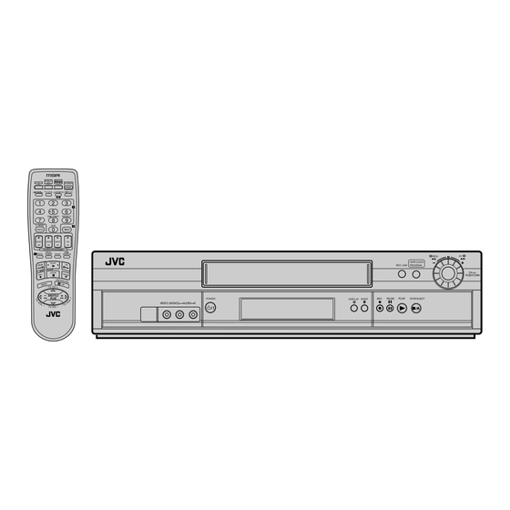
SERVICE MANUAL
VIDEO CASSETTE RECORDER
HR-S2901U, HR-S2911U(C),
HR-S3901U,
HR-S3911U, HR-S3911U(C)
Regarding service information other than these sections, refer to the HR-S5901U service manual (No.82911).
Also, be sure to note important safety precautions provided in the service manual.
SPECIFICATIONS
GENERAL
Power requirement
: AC 120 V
Power consumption
Power on
: 17 W
Power off
: 1.5 W
Temperature
Operating
: 5°C to 40°C (41°F to 104°F)
Storage
: –20°C to 60°C (–4°F to140°F)
Operating position
: Horizontal only
Dimensions (W x H x D) : 435 mm x 94 mm x 247 mm
(17-3/16" x 3-3/4" x 9-3/4")
Weight
: 2.8 kg (6.2 lbs)
Format
: S-VHS/VHS NTSC standard
Maximum recording time
SP
: 210 min. with ST-210 video cassette
EP
: 630 min. with ST-210 video cassette
VIDEO/AUDIO
Signal system
: NTSC-type color signal and EIA
monochrome signal, 525 lines/
60 fields
Recording/Playback
: DA-4 (Double Azimuth) head helical
system
scan system
Signal-to-noise ratio
: 45 dB
Horizontal resolution
VHS
: 230 lines
S-VHS
: 400 lines
Frequency range
Normal audio
: 70 Hz to 10,000 Hz
Hi-Fi audio
: 20 Hz to 20,000 Hz
Input/Output
: RCA connectors (IN x 2, OUT x 1)
S-video connectors (IN x 1, OUT x 1)
POWER
(The specifications shown pertain specifically to the model HR-S3901U.)
, 60 Hz
d
This service manual is printed on 100% recycled paper.
COPYRIGHT © 2002 VICTOR COMPANY OF JAPAN, LTD
REW
FF
24HR QUICK
REC LINK
PROGRAM
DISPLAY SP/EP
TUNER
Tuning system
: Frequency-synthesized tuner
Channel coverage
VHF
: Channels 2–13
UHF
: Channels 14–69
CATV
: 113 Channels
RF output
: Channel 3 or 4 (switchable; preset to
Channel 3 when shipped) 75 ohms,
unbalanced
TIMER
Clock reference
: Quartz
Program capacity
: 1-year programable timer/8 programs
Memory backup for timer is not supported.
ACCESSORIES
Provided accessories
: Infrared remote control unit,
"AA" battery x 2,
S-video cable (4-pin),
RF cable (F-type)
Specifications shown are for SP mode unless specified otherwise.
E. & O.E. Design and specifications subject to change without
notice.
V15S0/S1
No.82912
March 2002
Advertisement
Table of Contents

Related Manuals for JVC HR-S3911U


Summarization of Contents
SPECIFICATIONS
GENERAL
General specifications including power, temperature, dimensions, weight, and format.
TUNER
Tuner system, channel coverage, and RF output details.
TIMER
Timer functions including clock reference and program capacity.
ACCESSORIES
List of provided accessories with the unit.
Important Safety Precautions
Precautions during Servicing
Safety measures and guidelines to follow when servicing the unit.
SECTION 1 DISASSEMBLY
1.1 Manually removing the cassette tape
Procedure for manually removing a loaded cassette tape due to mechanical failure.
1.2 Removing the major parts
Steps for removing major external parts and board assemblies from the unit.
1.3 Emergency display function
Details on accessing and interpreting emergency display (EMG) information.
1.4 Service position
Procedure for setting the unit to a service position for diagnostics and repair.
1.5 Jig RCU mode
Modes for receiving remote control codes, including User and Jig RCU modes.
1.6 Mechanism service mode
Function to enter the mechanism into operation modes without a cassette.
1.7 Maintenance and inspection
Guidelines for regular maintenance, cleaning, and lubrication of unit parts.
SECTION 2 MECHANISM
2.1 Before disassembling
Notes and checks before disassembling the mechanism assembly.
2.2 Replacement of the main mechanism parts
Procedures for removing and installing main mechanism parts like cassette holder and heads.
2.3 Mechanism timing chart
Timing chart illustrating the sequence of operations for different mechanism modes.
SECTION 3 ADJUSTMENT
3.1 Before adjustment
Precautions, test equipment, and tools required for unit adjustments.
3.2 Mechanism compatibility adjustment
Adjustments for mechanism compatibility, particularly after parts replacement.
3.3 Electrical adjustment
Procedures for electrical adjustments, including servo, video, and audio circuits.
SECTION 4 CHARTS AND DIAGRAMS
NOTES OF SCHEMATIC DIAGRAM
Important safety notes and conventions for schematic diagrams.
SCHEMATIC DIAGRAM CONVENTIONS
Conventions for interpreting schematic diagrams, including units and symbols.
4.1 BOARD INTERCONNECTIONS
Diagram showing interconnections between various boards of the unit.
4.2 MAIN (VIDEO/N.AUDIO) SCHEMATIC DIAGRAM
Schematic diagram for the main board's video and N.Audio sections.
4.3 MAIN (S-SUB) SCHEMATIC DIAGRAM
Schematic diagram for the main board's S-SUB section.
4.4 MAIN (SYSCON) SCHEMATIC DIAGRAM
Schematic diagram for the main SYSCON (System Control) board.
4.5 MAIN (SW.REG) SCHEMATIC DIAGRAM
Schematic diagram for the main switching regulator (SW.REG) section.
4.6 MAIN (TUNER) SCHEMATIC DIAGRAM
Schematic diagram for the main tuner section.
4.7 MAIN (FMA/DEMOD) SCHEMATIC DIAGRAM
Schematic diagram for the main FMA/DEMOD section.
4.8 MAIN (FRONT) SCHEMATIC DIAGRAM
Schematic diagram for the main front panel section.
4.9 MAIN (TERMINAL) SCHEMATIC DIAGRAM
Schematic diagram for the main terminal connections.
4.10 2D DIGITAL SCHEMATIC DIAGRAM
Schematic diagram for the 2D digital processing section.
4.11 2D DIGITAL CIRCUIT BOARD
Component location guide for the 2D Digital Circuit Board.
4.13 REMOTE CONTROLLER SCHEMATIC DIAGRAM
Schematic diagram of the remote controller unit.
4.14 WAVEFORMS
Illustrations of various waveforms measured at different test points.
4.15 VOLTAGE CHARTS
Charts indicating voltage measurements for different modes and sections.
4.16 FDP GRID ASSIGNMENT AND ANODE CONNECTION
Assignment of FDP grid digits and anode connections.
4.17 CPU PIN FUNCTION
Detailed functions of each pin on the System Control Microcomputer (IC3001).
4.18 SYSTEM CONTROL BLOCK DIAGRAM
Block diagram illustrating the system control architecture and signal flow.
4.19 VIDEO BLOCK DIAGRAM
Block diagram showing the video signal processing path.
4.20 AUDIO BLOCK DIAGRAM
Block diagram illustrating the audio signal processing path.
SECTION 5 PARTS LIST
SAFETY PRECAUTION
Safety precautions for replacing parts, identifying critical components.
PACKING AND ACCESSORY ASSEMBLY
Parts list for packing and accessory items.
FINAL ASSEMBLY
Parts list for the final assembly of the unit.
MECHANISM ASSEMBLY
Detailed parts list for the mechanism assembly.
ELECTRICAL PARTS LIST
List of electrical components used in various assemblies.
2D DIGITAL BOARD ASSEMBLY <05>
Parts list for the 2D Digital Board Assembly.
A/C HEAD BOARD ASSEMBLY <12>
Parts list for the A/C Head Board Assembly.
REAR S JACK BOARD ASSEMBLY <29>
Parts list for the Rear S Jack Board Assembly.
FRONT S JACK BOARD ASSEMBLY <36>
Parts list for the Front S Jack Board Assembly.
ADV.JOG / SW BOARD ASSEMBLY <38>
Parts list for the Adv. Jog/SW Board Assembly.
LOADING MOTOR BOARD ASSEMBLY <55>
Parts list for the Loading Motor Board Assembly.
R.PAUSE BOARD ASSEMBLY <99>
Parts list for the R. Pause Board Assembly.
Need help?
Do you have a question about the HR-S3911U and is the answer not in the manual?
Questions and answers