
Related Manuals for Potter intelligen INS-2000

Summary of Contents for Potter intelligen INS-2000
- Page 1 INS-1500/2000 (EU) Nitrogen Generators Installation, Operation, and Instruction Manual St. Louis, MO Manual #5403653 - F 800-325-3936 5/23 www.pottersignal.com...
- Page 2 Many States, Localities and Countries have codes and regulations governing sales, construction, installation, and/or use of products for certain purposes, which may vary from those in neighboring areas. While Potter attempts to assure that its products comply with such codes, it cannot guarantee compliance, and cannot be responsible for how the product is installed or used. Before purchase and use of a product, please review the product application, and national and local codes and regulations, and be sure that the product, installation, and use will comply with them.
-
Page 3: Table Of Contents
Nitrogen Functionality Test ....................................22 Filling the Sprinkler System and Purging ................................23 ® Purging with IntelliPurge Nitrogen Purge Valve (INS-PV) ..........................24 Purging with Potter Nitrogen Purge Valve (NGP-SPV) ............................ 25 ™ IntelliView Dashboard Internet Connectivity ..............................26 ®... -
Page 4: Safety Guidelines
This manual contains safety information that is important to know and understand. This information is provided for the safety of installers, operators, and users of the Potter Nitrogen Generator as well as equipment. To help recognize this information, observe the following symbols. - Page 5 The warnings in this manual cover most known potential hazards, but by definition cannot be all-inclusive. If the user employs an operating procedure, item of equipment, or a method of working that is not specifically recommended by Potter Electric Signal Company, the user must ensure that the equipment will not be damaged or become hazardous to persons or property.
-
Page 6: System Overview
™ The Potter IntelliGen Nitrogen Series operates using membrane technology. The smaller oxygen and water vapor molecules can pass through (permeate) the membrane quickly. The larger nitrogen molecules are less likely to diffuse through the separator tubes;... -
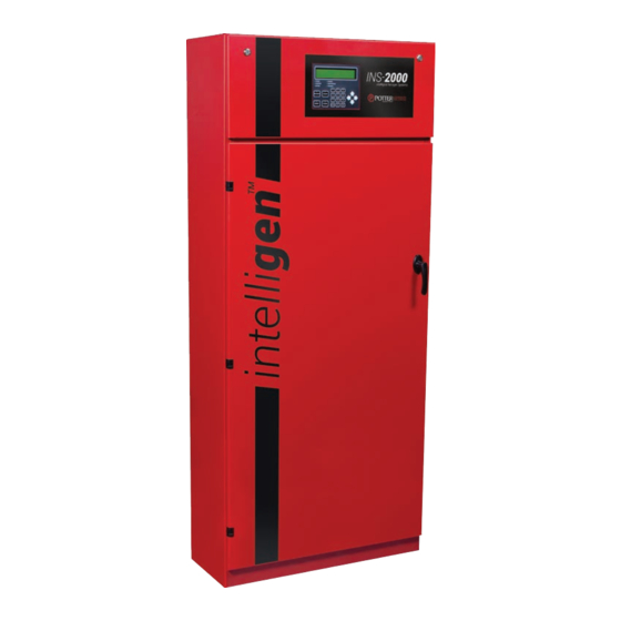
Page 7: Ins-1500/2000 (Eu) Exterior View
INS-1500/INS-2000 (EU) • 5403653 • REV F • 5/23 INS-1500/2000 (EU) Exterior Cabinet View Fig. 1 1. Upper Cabinet Latches (Qty. 2) 5. Locking Door Handle ™ 2. IntelliGen Display 6. Nitrogen Tank Connection (1/2" Female BSPT) 3. Control Power Only Switch 7. -
Page 8: Ins-1500/2000 (Eu) Interior View
INS-1500/INS-2000 (EU) • 5403653 • REV F • 5/23 INS-1500/2000 (EU) Interior View Fig. 2 1. Nitrogen Membrane (M01) 13. N Bleed Valve (V04) 2. Flow Control Valve (FCV01) 14. Bypass Solenoid Valve (XV03) 3. Back Pressure Regulator (PRV02) 15. Water Separator (WS01) 4. -
Page 9: Ins-1500/2000 (Eu) Nitrogen Tank View
INS-1500/INS-2000 (EU) • 5403653 • REV F • 5/23 INS-1500/2000 (EU) Nitrogen Tank View Fig. 3 1808mm [71 1/4"] 1304mm [51 3/8"] 82mm [3 1/4"] HOW LABEL) PERSPECTIVE VIEW (DONT SHOW LABEL) 1. 1/2" Female BSPT N Tank Inlet Valve (V02) 4. -
Page 10: Ins-1500/2000 (Eu) Air Compressor View
INS-1500/INS-2000 (EU) • 5403653 • REV F • 5/23 INS-1500/2000 (EU) Air Compressor View Fig. 4 1. Air Compressor Pressure Switch 6. Air Compressor Air Filter 2. Compressor Sensor Wire (20 ft. Provided) 7. 1/2" BSPT Air Tank Outlet Valve (V01) 3. -
Page 11: Intelligen Display
INS-1500/INS-2000 (EU) • 5403653 • REV F • 5/23 ™ IntelliGen Display: ™ ™ The IntelliGen Display is the interface to the IntelliGen Nitrogen Generator. This display shows the generator’s history, parameters, and troubles; as well as devices networked to the unit. Fig. -
Page 12: Installation Of The Nitrogen Generator
ITS SPECIFICATIONS AND VENDOR WILL BE RESPONSIBLE FOR ANY REWORK COST WHERE SPECIFICATIONS HAVE NOT BEEN MET. PROPRIETARY DATA DATA CONTAINED HEREIN SHALL NOT BE USED, DUPLICATED OR DISCLOSED IN WHOLE OR PART OUTSIDE POTTER ELECTRIC, INC. WITHOUT WRITTEN PERMISSION OF SAME. POTTER ELECTRIC SIGNAL CO. TITLE CAD GENERATED DRAWING,... - Page 13 ITS SPECIFICATIONS AND VENDOR WILL BE RESPONSIBLE FOR ANY REWORK COST WHERE SPECIFICATIONS HAVE NOT BEEN MET. PROPRIETARY DATA DATA CONTAINED HEREIN SHALL NOT BE USED, DUPLICATED OR DISCLOSED IN WHOLE OR PART OUTSIDE POTTER ELECTRIC, INC. WITHOUT WRITTEN PERMISSION OF SAME. Air Tank POTTER ELECTRIC SIGNAL CO. TITLE...
- Page 14 PROPRIETARY DATA DATA CONTAINED HEREIN SHALL NOT BE USED, DUPLICATED OR DISCLOSED IN WHOLE OR PART OUTSIDE POTTER ELECTRIC, INC. WITHOUT WRITTEN PERMISSION OF SAME. POTTER ELECTRIC SIGNAL CO. 13. Pipe the provided 3,05m (10') of 6,35mm (¼”) drain tubing on the tank mounted air compressor to the floor drain in the...
- Page 15 INS-1500/INS-2000 (EU) • 5403653 • REV F • 5/23 14. Pipe the provided 3,05m (10') of 9,5mm (3/8”) drain tubing on the nitrogen cabinet to the floor drain in the sprinkler room. Do not pipe the drain tubing upward. See Fig 15. Fig.
-
Page 16: Wiring Of The Nitrogen Generator
INS-1500/INS-2000 (EU) • 5403653 • REV F • 5/23 Wiring of the Nitrogen Generator Four items must be wired on the INS-1500 (EU) or INS-2000 (EU) models: • Air compressor (380-415V VAC - Three Phase) • Air tank blow-down located on the bottom of the tank mounted air compressor (220 VAC) •... -
Page 17: Compressor Sensor Wire
INS-1500/INS-2000 (EU) • 5403653 • REV F • 5/23 Compressor Sensor Wire 1. Locate the Compressor Sensor Wire on the tank mounted air compressor. See Fig 19. Fig. 19 Compressor Sensor Wire 2. Run the wire to the nitrogen cabinet through the cord grip provided on the right side of the nitrogen cabinet, labeled Compressor Sensor Wire 3. -
Page 18: Air Tank Blow-Down Located On The Bottom Of The Tank Mounted Air Compressor (220 Vac)
INS-1500/INS-2000 (EU) • 5403653 • REV F • 5/23 Air Tank Blow-Down Located on the Bottom of the Tank Mounted Air Compressor (230V) Locate the air tank blow-down on the bottom of the air tank. See Fig 21. Fig. 21 Air Tank Blow-down Using the provided 3,05m (10') of 220VAC cord, plug the blow-down into a dedicated wall outlet. -
Page 19: Internet Connectivity, Plink, And Bms (Optional)
INS-1500/INS-2000 (EU) • 5403653 • REV F • 5/23 Internet Connectivity, PLINK, and BMS (Optional) ™ 1. For internet connectivity (see the IntelliView section on page 26 for more details), wire a CAT-5 Ethernet cable using a M16 (1/2") knockout on the cabinet to the Ethernet Port on the IntelliGen ™... -
Page 20: Nitrogen Generator Operation
INS-1500/INS-2000 (EU) • 5403653 • REV F • 5/23 Nitrogen Generator Operation Initial Set Up: 1. Before beginning, make sure the water supply to the sprinkler system is turned off. 2. Make sure all piping connections have been made in accordance with the installation instructions. 3. - Page 21 INS-1500/INS-2000 (EU) • 5403653 • REV F • 5/23 The amber LED labeled "BYPASS" will activate if the pressure is less than 3,79 bar (379 kPa) (55 psi) in the nitrogen tank. Turn power ON to the air compressor using the customer supplied electrical disconnect. 10.
-
Page 22: Nitrogen Functionality Test
INS-1500/INS-2000 (EU) • 5403653 • REV F • 5/23 Nitrogen Functionality Test: To ensure the nitrogen generator is operating correctly and that the correct nitrogen purity is being produced a functional test must be performed. On the inside of the nitrogen cabinet locate the blue N Bleed Valve (V04). -
Page 23: Filling The Sprinkler System And Purging
INS-1500/INS-2000 (EU) • 5403653 • REV F • 5/23 Filling the Sprinkler System and Purging: 1. To fill the sprinkler system, open the N Tank Outlet Valve (V03) on the nitrogen tank and open the bypass valve on the Nitrogen Air Maintenance Device. See Fig. 30. Fig. -
Page 24: Purging With Intellipurge Nitrogen Purge Valve (Ins-Pv)
INS-1500/INS-2000 (EU) • 5403653 • REV F • 5/23 ® Purging with IntelliPurge Nitrogen Purge Valve (INS-PV): Fig. 31 Slotted Cam Latch Level % Display S2 Toggle Switch S1 Toggle Switch Power LED Purge LED Trouble LED Purge Time Display Purge Exhaust Port See Manual #5401532 for full details on installing, programming, purging and wiring of the INS-PV. -
Page 25: Purging With Potter Nitrogen Purge Valve (Ngp-Spv)
INS-1500/INS-2000 (EU) • 5403653 • REV F • 5/23 Purging with Potter Nitrogen Purge Valve (NGP-SPV): Fig. 32 1. See Bulletin #5401520 for full details on installing and purging of the NGP-SPV. 2. Go to the end of the sprinkler system(s) where the NGP-SPV(s) is installed. Each riser should have one NGP-SPV purge valve. -
Page 26: Intelliview Dashboard Internet Connectivity
A window will appear indicating that you have successfully added the nitrogen generator. Click save. The page will refresh with information on the new nitrogen generator. ™ For more information on the Potter IntelliView Dashboard, watch a tutorial at www.potterintelliview.com... -
Page 27: Intellipurge Wiring And Networking
IntelliPurge Wiring and Networking 1. The PLINK network is Potter’s propriety networking connection. It is a RS-485 network for serial communication between the Nitrogen Generator (INS Series) and its Purge Valves (INS-PV). 2. PLINK requires 3 signal lines to allow communication to and from the Nitrogen Generator and the Purge Valves. -
Page 28: Maintenance And Part Replacements
Nitrogen Generator should be performed by qualified personnel using reasonable care. Before servicing, isolate all risers by closing all Nitrogen Air Maintenance Device valves and relieving all system pressure from the Potter Nitrogen Generator. Failure to do so could result in serious injury or death. Ensure power is turned off at the electrical disconnect. -
Page 29: Standard Maintenance
ITS SPECIFICATIONS AND VENDOR WILL BE RESPONSIBLE FOR ANY REWORK COST WHERE SPECIFICATIONS HAVE NOT BEEN MET. PROPRIETARY DATA DATA CONTAINED HEREIN SHALL NOT BE USED, DUPLICATED OR DISCLOSED IN WHOLE OR PART OUTSIDE POTTER ELECTRIC, INC. WITHOUT WRITTEN PERMISSION OF SAME. -
Page 30: Compressor Air Intake Filters
INS-1500/INS-2000 (EU) • 5403653 • REV F • 5/23 Compressor Air Intake Filters: When the pressure has been drained from the nitrogen generator replace the air intake filter element. Remove air filter cover from compressor. See Fig. 39 Fig. 39 Remove air filter element. -
Page 31: Air Tank Blow-Down Strainer
INS-1500/INS-2000 (EU) • 5403653 • REV F • 5/23 Air Tank Blow-Down Strainer Screen: 11. Locate the inline blow-down strainer on the bottom of the air tank. Using a channel lock loosen the strainer screen cap. See Fig. 40. Fig. 40 Blow-down strainer 12. -
Page 32: Filter Elements
INS-1500/INS-2000 (EU) • 5403653 • REV F • 5/23 Filter Elements: 20. Locate the four (4) filters on the inside of the nitrogen generator cabinet. See Fig. 42. The Water Separator labeled WS01 does not have a replaceable element. Note: Fig. - Page 33 INS-1500/INS-2000 (EU) • 5403653 • REV F • 5/23 22. Using an adjustable wrench loosen the filter bowl from the filter body. See Fig. 44. Fig. 44 CAREFULLY WRENCH HERE DO NOT PLACE ONLY WRENCH HERE CAUTION Fig. 45 It is extremely important that you only unscrew the drain bowl from the filter body. The float adjustments at the bottom must remain in auto.
-
Page 34: Resetting Maintenance Alert And Checking For Leaks
INS-1500/INS-2000 (EU) • 5403653 • REV F • 5/23 25. Remove old O-rings and replace with the O-rings in the filter element kit. 26. Clean filter bowls of debris. 27. Screw the filter bowl back into the filter body. Use an adjustable wrench to tighten the correct wrenching flats. Be careful to not over tighten or you may crack the filter body. -
Page 35: Air Compressor Replacement
INS-1500/INS-2000 (EU) • 5403653 • REV F • 5/23 Air Compressor Replacement 1. See Ingersoll Rand Air Compressor Manual #7348130000. Nitrogen Membrane Replacement 1. Isolate the nitrogen generator from the sprinkler system. 2. Disconnect power to the nitrogen generator using lockout-tagout procedure. 3. -
Page 36: Maintenance Alerts And Actions
INS-1500/INS-2000 (EU) • 5403653 • REV F • 5/23 Maintenance Alerts and Actions A maintenance alert is noncritical to the operation of the nitrogen generator. The maintenance light will turn on and a maintenance ™ ™ alert will appear on the IntelliGen Display and IntelliView website, and an e-mail will also be sent. -
Page 37: Trouble Alerts And Probable Causes
INS-1500/INS-2000 (EU) • 5403653 • REV F • 5/23 Trouble Alerts and Probable Causes A trouble alert is a critical alert to the operation of the nitrogen generator. The trouble light will turn on and a trouble alert will ™ ™... - Page 38 INS-1500/INS-2000 (EU) • 5403653 • REV F • 5/23 Trouble Alert #5 - Excessive Membrane Cycling Issue: Nitrogen valves turn ON 16 (INS-1500) or 24 (INS-2000) times in 4 hours. Probable Cause: Leak on sprinkler system. Leak on nitrogen tank. Pressure settings need to be adjusted or pressure transducer replaced.
-
Page 39: Troubleshooting
INS-1500/INS-2000 (EU) • 5403653 • REV F • 5/23 Troubleshooting Leak on Sprinkler System or Nitrogen Generator ™ 1. View the Leak Rate (LR) by exiting to the main menu of the IntelliGen Display. It will be displayed as LR: # bar/24HR. 2. -
Page 40: Normal Operating Parameters Of The Ins-1500/2000 (Eu)
Normal Operating Parameters of the INS-1500 (EU) and the INS-2000 (EU) Nitrogen Generators use a two tank system design to deliver high purity nitrogen to the fire protection The Potter IntelliGen ™ system. The pressure switch on the air tank controls the air compressor by turning it on and off at the desired pressure set points. -
Page 41: Nitrogen Generator Leak Detection System
™ The Leak Rate Warning Set Point in the Potter IntelliGen Nitrogen Generator is a user adjustable set point for when a maintenance or trouble alert is activated. It will give a preemptive warning that the system Leak Rates have increased above the acceptable level. -
Page 42: To Change The Leak Rate Warning Set Point
Using the directional arrows, adjust the leak rate limit number "--" bar per 24 hours. NFPA allows 0,103 bar (10,3 kPa) (1.5 psi) per 24 hours on new systems. Potter Nitrogen Generators are designed for 0,41 bar (41 kPa) (6 psi) per 24 hours. Press "ENTER" to confirm. -
Page 43: Ins-1500/2000 (Eu) Cabinet Dimensional Drawings
INS-1500/INS-2000 (EU) • 5403653 • REV F • 5/23 INS-1500/2000 (EU) Cabinet Dimensional Drawings Fig. 48 CONNECTION CONNECTION DRAIN CONNECTION... - Page 44 LOCATED 120° ON A SPECIFICATIONS HAVE NOT BEE [20"] Ø570mm (22 1/2") BOLT DATA CONTAINED HEREIN SHAL CIRCLE (3 PLCS) OR PART OUTSIDE POTTER ELECT POTTER EL CAD GENERATED DRAWING, 825mm DO NOT MANUALLY UPDATE [32 1/2"] DO NOT SCALE DRAWING...
-
Page 45: Ins-1500/2000 (Eu) Compressor Dimensional Drawings
INS-1500/INS-2000 (EU) • 5403653 • REV F • 5/23 INS-1500/2000 (EU) Compressor Dimensional Drawings Fig. 50 6.1m (20’) -
Page 46: Ins-1500/2000 (Eu) Piping Instrumentation Diagram
INS-1500/INS-2000 (EU) • 5403653 • REV F • 5/23... -
Page 47: Wiring Diagrams
INS-1500/INS-2000 (EU) • 5403653 • REV F • 5/23... -
Page 48: Menu Trees
INS-1500/INS-2000 (EU) • 5403653 • REV F • 5/23 Menu Trees 1. Menu Tree 1 Title Screen Model Number Status: ## Mode: ## N2 Tank: ## Leak Rate (LR): ## 5) Settings 1) System Status 2) View History 3) Maintenance 4) Purge Menu Tree 2 Menu Tree 3... -
Page 49: Menu Tree 2
INS-1500/INS-2000 (EU) • 5403653 • REV F • 5/23 2. Menu Tree 2 Main Menu 1) System Status Screen 2) Purge Status 1) Generator Status Device Number: ## N2 Level: ## Days Remaining: ## Compressor: Total Run Time: ## Average Cycle Time: ## Purge Mode: ## Purge Status: ## Press [ENTER] for Viewable Parameters... -
Page 50: Menu Tree 3
INS-1500/INS-2000 (EU) • 5403653 • REV F • 5/23 3. Menu Tree 3 Main Menu 2) View History History 1) Generator History 2) INS-PV History Generator INS-PV History: History: Scrollable list of Scrollable list of connected all history from INS-PV devices N2 generator INS-PV: Scrollable list of... -
Page 51: Menu Tree 4
INS-1500/INS-2000 (EU) • 5403653 • REV F • 5/23 4. Menu Tree 4 Main Menu 3) Maintenance 1) Standard 2) Excessive Nitrogen Nitrogen Demand Maintenance Maintenance Timer: ## Excessive Nitrogen Demand: Reset Maintenance Timer Clear Maintenance Alert [ENTER] [ENTER] Reset Maintenance Timer Press Enter to Clear Maintenance Alert... -
Page 52: Menu Tree 5
INS-1500/INS-2000 (EU) • 5403653 • REV F • 5/23 5. Menu Tree 5 Main Menu 4) Purge 1) Start Purge 3) Settings 2) Cancel Purge Purge Start Cancel Purge Settings 1) All Devices 1) All Units 1) Purge Settings 2) Specify INS-PV 2) Specify INS-PV 2) Manual Purge 3) Refresh N2 Lvl %... -
Page 53: Menu Tree 6
INS-1500/INS-2000 (EU) • 5403653 • REV F • 5/23 6. Menu Tree 6 1) Purge Settings Purge Settings Restore Factory Default 1) Set All Units 2) Set Individual INS-PV 1) All Units 3) Purge Scheduling 2) Individual INS-PV 4) Restore Factory Default Set All Units Purge Scheduling Settings Set Individual INS-PV... -
Page 54: Menu Tree 7
INS-1500/INS-2000 (EU) • 5403653 • REV F • 5/23 7. Menu Tree 7 5) Settings Main Menu 1) Network 2) Date/Time 3) Leak Rate 4) Blow Down 5) BMS Test 6) Admin. Leak Rate Screen Air Tank Blow Down Date/Time Network Leak Rate: ## BMS Test...
Need help?
Do you have a question about the intelligen INS-2000 and is the answer not in the manual?
Questions and answers