Table of Contents
Advertisement
Quick Links
Advertisement
Table of Contents

Related Manuals for MISUMI MTCTS

Summary of Contents for MISUMI MTCTS
- Page 1 DIGITAL TEMPERATURE CONTROLLER...
-
Page 2: Operating Environment
SPECIFICATIONS MTCTR:Relay contact MTCTS:SSR drive voltage... -
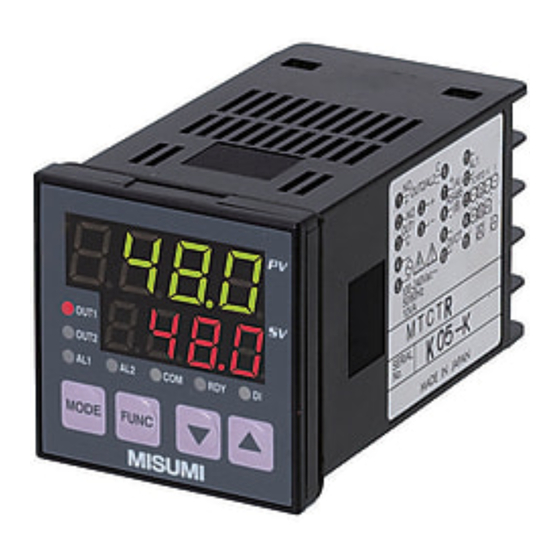
Page 3: Parts Indication
CAUTION BEFORE CONTROL ・Set-up program is stored operation, as non-volatile memory, is equipped with the controllers. ・Either thermocouple or R.T.D.(Pt 100/JPt100) is selectable input type, but Current/Voltage input needs to be selected individually. - Page 4 3)Wiring EV2 (For alarm) EV1 (For alarm) ① ⑥ ⑪ Relay output Relay output 250V AC 2.4A(Load resistance) 250V AC, 2.4A ⑫ (Load resistance) ① ⑥ ⑪ ② ...
- Page 5 SET-UP PARAMETERS BEFORE USAGE ・Follow the instructions below to set-up parameters *If advanced set-up is required, refer to “Operation Flow and Setting” screen. ...
- Page 6 ALARM OPERATING RANGE Deviation AL1L AL1H Absolute value AL1H high and low high and low AL1L limit limit...
-
Page 7: Mode Key
OPERATION FLOW AND SETTING MENU ●Power ON Shows for 4 seconds (Warming up) ●Operate mode display Primary displays Process value PV Set the temperature... - Page 8 ●Setting mode (The numerical value of display is an initial value. ) <SET1:Initial Setting> <SET2:Control Setting> <SET3:Event Output 1> 1.Initial Setting display ▲ key 9.Initial Setting display ▲ key 37.Event output 1 Setting SET SET SET Initial setting mode Control setting mode EV 1 setting mode Calling display 1 2 3 Calling display ▼ key Calling display ▼ key MODE key MODE key MODE key 2.Input type setting 10.High limit setting in SV limiter 38.Function setting for EV 1 Display of high limit setting of ̲SLH ̲E1F PV Select input type setting value. Select below functions. 00 1200 00 SV Refer to Table 1.
- Page 9 <SET4:Event Output 2> <SET7:Timer> <SET0:Priority Displays> ▲ key 47.Event output 2 Setting ▲ key 67.Timer setting ▲ key 74.Priority displays setting SET SET SET SET SET SET SET SET Timer setting mode EV 2 setting mode Calling Select priority displays display Calling display (Refer to Ex.1.) 4 1 7 1 0 ▼ key ▼ key ▼ key Calling display MODE key MODE key MODE key 48.Function setting for EV 2 68.Timer output setting 75.Setting for 1st priority displays ̲E2F ̲tMn Pr1 1 Select 1st display on Select below functions.
- Page 10 (Display) (Description) (Trouble Shooting) Shown whenever input value exceeds Check the snapping of thermocouple − − − − the high limit of display range. Also and R.T.D. input. display when the wire thermocouple, ABb-terminal of R.T.D is snapped off. Check short circuit of input lines Shown whenever input value exceeds _...
- Page 11 〜MEMO〜 - 10 -...
- Page 12 Please contact your local MISUMI office or below MISUMI Corporation Phone : (81)120-343-603 - 11 -...
Need help?
Do you have a question about the MTCTS and is the answer not in the manual?
Questions and answers