
Related Manuals for Eaton Crouse-Hinds MTL5553


Summary of Contents for Eaton Crouse-Hinds MTL5553
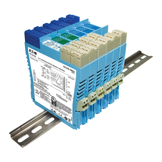
- Page 1 Instruction manual July 2019 MTL intrinsic safety solutions INM 5500 Rev 11 MTL5500 range Isolating interface units...
-
Page 2: Declaration Of Conformity
DECLARATION OF CONFORMITY A printed version of the Declaration of Conformity has been provided separately within the original shipment of goods. However, you can find a copy of the latest version at: http://www.mtl-inst.com/certificates INM 5500 Rev 11... -
Page 3: Table Of Contents
CONTENTS DECLARATION OF CONFORMITY . . . . . . . . . . . . . . . . . . . . . . . . . . . . . . . . . . . . . . . . . . . . . . . . . . . . . . II IMPORTANT NOTE . - Page 4 Table C - Maximum cable parameters - IIB gas group . . . . . . . . . . . . . . . . . . . . . . . . . . . . . . . . . . . . . . . . . 77 © 2019 Eaton Electric Limited. All rights reserved.
-
Page 5: Important Note
IMPORTANT NOTE WARNING This manual has content describing the use and installation of safety equipment . This equipment must be installed, operated and maintained only by trained competent personnel and in accordance with all appropriate international, national and local standard codes of practice and site regulations for intrinsically safe apparatus and in accordance with the instructions contained here . -
Page 6: Atex Safety Instructions
ATEX SAFETY INSTRUCTIONS The following information is in accordance with the Essential Health and Safety Requirements (Annex II) of the EU Directive 2014/34/EU [the ATEX Directive - safety of apparatus] and is provided for those locations where the ATEX Directive is applicable. General a) This equipment must only be installed, operated and maintained by competent personnel. - Page 7 Inspection and maintenance a) Inspection and maintenance should be carried out in accordance with European, national and local regulations which may refer to the IEC standard IEC 60079-17. In addition specific industries or end users may have specific requirements which should also be met. b) Access to the internal circuitry must not be made during operation.
- Page 8 This page is left intentionally blank viii INM 5500 Rev 11...
-
Page 9: Introduction
INTRODUCTION This instruction manual describes the procedures for installing, connecting, checking and maintaining MTL5500 range of isolating interfaces and accessories. The MTL5500 products provide a DIN-rail mounted, intrinsically safe interface to hazardous areas of a process plant. The individual sections of this manual cover the following topics •... - Page 10 The table below lists the modules in the MTL5500 range. Refer also to the individual MTL5500 range of data sheets. Digital Input Channels Function MTL5501-SR fail-safe, solid-state output + LFD alarm MTL5510 switch/prox input, solid-state output MTL5510B multi-function, switch/prox input, solid-state output MTL5511 switch/prox input, c/o relay output MTL5513...
-
Page 11: Installation
• If in doubt, refer to the certificate/catalogue for clarification of any aspects of intrinsic safety or contact Eaton’s MTL product line or your local representative for assistance. • Make sure the correct hazardous-area connector (field-wiring plug) is plugged into the corresponding isolator. -
Page 12: Modules - Pre-Installation
3 .1 Modules – pre-installation 3 .1 .1 Switch settings for operating conditions Some modules have operating conditions, such as Line-Fault Detection (LFD), Phase Reversal, etc., that can be established by the setting of switches on the unit. The subminiature switches are accessible through an aperture on the side of the module (see Figure 3.2) and can be set in the required positions with, for example, the blade of a small screwdriver. - Page 13 3 .2 .2 Wiring up isolators Each unit is supplied with the appropriate number and type of safe- and hazardous-area connectors (see Figure 3.4), as dictated by the terminals used and the type of power supply. with ferrule Power Plugs Grey: dc supplies (PWR5000) 12mm trim...
-
Page 14: Accessories
3 .2 .2 .3 Finishing Wire up individual isolators in accordance with wiring schedules. Daisy-chain power supply connections between individual power plugs or use the power bus (see section 4.1). Segregate hazardous- and safe-area wiring into separate trunking or looms wherever possible to avoid errors and maintain a tidy installation. -
Page 15: Mpa5500 Ac Power Adaptor
4 .2 MPA5500 AC power adaptor When only one or two MTL5500 modules are required for a particular application, it may be desirable to power the units from the AC mains supply directly, rather than use a separate DC supply unit. The MPA5500 is an adaptor that plugs into the DC power socket on the side edge of an MTL5500 module and clips securely onto the module housing. -
Page 16: Earth Rail And Tagging Accessories
4 .3 Earth rail and tagging accessories This section explains how to specify and assemble earth rail and tagging strip accessories for the MTL5500 range. The accessories consist of mounting brackets, earth rails, tagging strips and associated parts. They provide facilities for earthing, terminating cable screens and tagging (identifying) the positions of individual units. - Page 17 TGL57 THR2 TAG57 Snap off extension ERB57S IMB57 PWR5000 when using IMB57 as central support ERB57 10mm Earth 14mm clamp Earth-rail clamp ETM7 Push ERL7 ERB57S fastener in upper position ERB570 ERB57S SAF10-12 in lower ERL7 SAF7-9 position IMB57 TH5000 ETM7 TGL57 HAZ1-3...
- Page 18 Figure 4 . 1 0: Fitting IMB57 Slide a straight earth-rail bracket ERB57S into the upper slot in each mounting block. Push two plastic push fasteners into each bracket to locate the brackets in the mounting blocks. Cut earth rail ERL7 to the length needed. Slide the required number of ETM7 earth terminals (5mm or 7mm wide) onto the rail.
- Page 19 110mm 110mm Figure 4 . 1 1: MTL5500 complete assembly Colour Module no . Function Yellow MTL5501-SR Digital Inputs White MTL551x MTL552x Digital Outputs Blue MTL5531/33 Vibration Purple MTL5532 Pulse MTL5541x Blue Analogue Inputs MTL5544x MTL5546x Green Analogue Outputs MTL5549x Blue MTL556x Fire &...
-
Page 20: Dx Enclosures
DX ENCLOSURES Enclosures are usually selected on the basis of the number of units they will accommodate and Table 5.1 shows the capacity of each of the enclosures. Figure 5.2 shows each type of enclosure containing MTL5500 modules. Table 5 .1: DX range of enclosures - module capacities Enclosure Number of MTL5500 isolators 16mm mounting pitch... - Page 21 Figure 5 .3: Optimum orientation for wall mounted enclosure DX070 DX170 MTL5500 4.03 1.88 Table 5 .2: Dissipation constant k for enclosures (°C/watt) Orientation of the enclosures is also important - the optimum position being on a vertical surface with the internal DIN-rail horizontal as shown in Figure 5.3.
- Page 22 Ø 5.2 DX070 113.5 153.5 Ø 7.2 DX170 Top of DIN rail n .b . DX430 no longer available Ø 7.2 DX430 Top of DIN rail Figure 5 .2: DX range of enclosures INM 5500 Rev 11...
- Page 23 5 .1 .5 Corrosion resistance The effect of corrosion on DX enclosures is negligible. 5 .1 .6 Flammability rating The flammable properties of the materials used in the construction of the enclosures are well understood by manufacturers and ratings have been established to a number of standards. One of the better known standards is the Underwriter's Laboratory standard UL 94 and the ratings for the enclosure materials are given as: Materials...
-
Page 24: Mounting
5 .2 .2 .2 Orientation As noted earlier (see section 5.1.1), for optimum temperature performance the enclosures should be mounted on a vertical surface with the internal DIN rail horizontal. 5 .2 .3 Mounting details See Figure 5.2 for the dimensions and mounting hole distances, etc., of the three DX enclosures. The recommended method of mounting-described here-uses the four wall-mounting lugs supplied with each enclosure. -
Page 25: Accessories In Enclosures
5 .3 Accessories in enclosures Apart from mounting, there are some other installation details which should be considered before adding the appropriate interface modules and making the necessary cabling connections. A range of accessories is available to accompany the MTL5500 units (see section 4) and the following points should be observed. -
Page 26: Unit Descriptions, Setting-Up And Connections
UNIT DESCRIPTIONS, SETTING-UP AND CONNECTIONS This section describes the function (briefly), the setting-up procedure and the wiring connections for each MTL5500 unit. For a fuller functional description and a detailed technical specification, refer to the individual datasheets, which can be found on our website at http://www.mtl-inst.com or in the current MTL IS catalogue. -
Page 27: Digital Input Modules
6 .1 Digital Input modules The Digital Input (DI) module range offers solid state or relay output switches in a safe area that respond to input switches located in a hazardous area. Single or multiple channel (2 or 4) options are available, as well as Line-Fault Detection (LFD). -
Page 28: Mtl5501-Sr - Fail-Safe Switch/Proximity Detector Interface
6 .1 .3 MTL5501-SR - Fail-safe Switch/Proximity detector interface Single channel, fail-safe module with line-fault detection The MTL5501-SR enables a fail-safe switch/proximity detector located in the hazardous area to control an isolated fail-safe electronic output. It provides line-fault detection (LFD) alarm contacts and is designed for use with approved fail-safe sensors in loops that require operation up to SIL3 according to the functional safety standard IEC 61508. -
Page 29: Mtl5510 & Mtl5510B - Switch/Proximity Detector Interface
6 .1 .4 MTL5510 & MTL5510B - Switch/Proximity detector interface 4-channel, digital input and multifunction modules These digital modules provide solid state output switches in a safe area that respond to switches (inputs) located in a hazardous area. The way they respond - their “mode” - can be configured using a bank of four DIL selector switches accessible through the side of the module - see Figure 6.4. - Page 30 1 2 3 4 OFF position ON position Figure 6 .4: DIL switches for setting mode Tables 6.1 and 6.2 show details of the modes available and the switch settings required to obtain them. For ease of access, it is recommended that switches are set to the required mode before installation. Table 6.1 indicates whether the output follows the input, or the output is the reverse or antiphase of the input.
- Page 31 MTL5510B modes The following logic and timing diagrams are provided to assist the user in understanding the behaviour of the MTL5510B module when a specific mode is chosen. The open switch ( ) and closed switch ( ) symbols are used to represent both the input conditions of Ch A, Ch B, Ch C or Ch D and then the output conditions of o/p 1, 2, 3 or 4.
- Page 32 MTL5510B modes - continued Mode 9: 2 ch with line fault output Mode 10: As mode 9 with line fault c/o i/p - Ch A i/p - Ch A Line Line Line Line fault fault fault fault fault fault fault fault o/p 1 o/p 1...
-
Page 33: Mtl5511 - Switch/Proximity Detector Interface
6 .1 .5 MTL5511 - Switch/Proximity detector interface Single channel, with line-fault detection The MTL5511 contains a changeover relay, which enables a safe-area load to be controlled by a switch or proximity detector located in a hazardous-area. When selected, the line-fault detect (LFD) facility detects open or short circuit conditions in the field wiring and also indicates this on the top of the module. -
Page 34: Mtl5513 - Switch/Proximity Detector Interface
6 .1 .6 MTL5513 - Switch/Proximity detector interface Two-channel, with line-fault detection and phase reversal The MTL5513 enables two solid-state outputs in the safe area to be controlled by two switches or proximity detectors located in the hazardous area. The Ch1/Ch2 output transistors share a common terminal and can switch +ve or -ve polarity signals. -
Page 35: Mtl5514/ Mtl5514D/Mtl5514-T - Switch/Proximity Detector Interface
6 .1 .7 MTL5514(-T)/MTL5514D - Switch/Proximity detector interface Single channel, with line-fault detection and phase reversal The MTL5514(-T) enables a safe-area load to be controlled, through a relay, by a proximity detector or switch located in a hazardous area. Line faults are signalled through a separate relay and indicated on the top of the module. -
Page 36: Mtl5516C - Switch/Proximity Detector Interface
6 .1 .8 MTL5516C - Switch/Proximity detector interface Two channel, with line-fault detection The MTL5516C contains two changeover relays, which enable two safe-area loads to be controlled by switches or proximity detectors located in a hazardous-area. When selected, the line-fault detect (LFD) facility detects open or short circuit conditions in the field wiring and also indicates this on the top of the module. -
Page 37: Mtl5517 - Switch/Proximity Detector Interface
6 .1 .9 MTL5517 - Switch/Proximity detector interface Two channel, with line-fault detection and phase reversal The MTL5517 enables two safe-area loads to be controlled, through a relay, by switches or proximity detectors located in a hazardous-area. When selected, the line-fault detect (LFD) is signalled through a separate relay and indicated on the top of the module. -
Page 38: Digital Output Modules
6 .2 Digital Output modules The single channel Digital Output (DO) module range enables on/off devices in a hazardous area to be controlled from the safe area. Some units are loop powered while others enable solid-state switching by providing independent power supplies. 6 .2 .1 MTL5521(-T) - Solenoid Alarm driver Single channel, loop powered, IIC... -
Page 39: Mtl5522 - Solenoid Alarm Driver
6 .2 .2 MTL5522 - Solenoid Alarm driver Single channel, loop powered, IIB The MTL5522 is a loop-powered module which enables a device located in the hazardous area (IIB gas group) to be controlled from the safe area. The MTL5522 can drive a certified intrinsically safe, low-power load as well as non-energy-storing simple apparatus such as an LED. -
Page 40: Mtl5523 - Solenoid Alarm Driver
6 .2 .3 MTL5523 - Solenoid Alarm driver Single channel, with line-fault detection, IIC The MTL5523 interface controls an on/off device in a hazardous area using a volt-free contact or logic signal in the safe area, and is suitable for driving loads such as solenoids. Line-Fault Detection (LFD) operates independently of the output state and is signalled by a safe-area, solid-state switch output which, when a field line is open or short-circuited, becomes de- energised. -
Page 41: Mtl5523V/Mtl5523Vl - Solenoid Alarm Driver
6 .2 .4 MTL5523V/MTL5523VL - Solenoid Alarm driver Single channel, voltage controlled with line-fault detection, IIC With the MTL5523V or MTL5523VL interface, an on/off device in a hazardous area can be controlled by a voltage signal in the safe area. It is suitable for driving loads such as solenoids. Line fault detection (LFD), which operates irrespective of the output state, is signalled by a safe- area, solid-state switch which energises if a field line is open or short–circuited. -
Page 42: Mtl5524 - Solenoid Alarm Driver
6 .2 .5 MTL5524 - Solenoid Alarm driver Single channel, powered, logic drive with phase reversal The MTL5524 enables an on/off device in a hazardous area to be controlled by a volt-free contact or logic signal in the safe area. It can drive loads such as solenoids, alarms, LEDs and other low power devices that are certified as intrinsically safe or are classified as non-energy- storing simple apparatus. -
Page 43: Mtl5525 - Solenoid Alarm Driver
6 .2 .6 MTL5525 - Solenoid Alarm driver Single channel, low current, loop powered, IIC The MTL5525 enables an on/off device in a hazardous area (IIC gas group) to be controlled by a switch or voltage change in the safe area. It can drive loads such as solenoids, alarms, LEDs and other low power devices that are certified as intrinsically safe or are classified as non-energy-storing simple apparatus. -
Page 44: Mtl5526 - Switch Operated Relay
6 .2 .7 MTL5526 - Switch Operated Relay Two channel, output The MTL5526 enables two separate IS circuits in a hazardous area to be relay-contact controlled by two on-off switches or logic signals in a safe area. Applications include the calibration of strain–gauge bridges;... -
Page 45: Pulse, Vibration And Foundation Fieldbus Modules
• Close packed = 45°C • Minimum of 10mm spacing = 55°C Eaton produce the MS010 DIN rail module spacer for this purpose (packs of 5 - see Section 4 .3) *Revision status is the 2 digits after the +++ in the barcode number... -
Page 46: Mtl5532 - Pulse Isolator
6 .3 .2 MTL5532 - Pulse Isolator Pulse & 4/20mA current outputs The MTL5532 isolates pulses from a switch, proximity detector, current pulse transmitter or voltage pulse transmitter located in a hazardous area. It is ideal for applications involving high pulse rates and fast response times, by repeating the pulses into the safe area, and the transistors used on the pulse output will switch +ve or –ve polarity signals. - Page 47 Switch input operation If switch contacts are used for this Pulse Input (terminals 1 & 2), then and parallel resistors must be fitted - see Section 6.1.2 for recommended values. Simple or Legacy mode - SW4 - OFF If simple “pulse-in/pulse-out” operation is required or, if a replacement for the earlier MTL5032 pulse isolator is required, then SW4 should be set to OFF .
-
Page 48: Mtl5533 - Vibration Transducer Interface
DIN rail with a 10mm space between adjacent units . Eaton produce the MS010 DIN rail module spacer for this purpose (packs of 5 - see Section 4 .3), and these then enable operation in ambient temperatures of up to 50°C in vertical or horizontal orientation . -
Page 49: Mtl5553- Isolator/Power Supply For 31.25Kbits/S Fieldbuses
6 .3 .4 MTL MTL5553 isolator/power supply for 31 .25kbit/s fieldbuses The MTL5553 has been specifically developed to extend 31.25kbit/s (H1) fieldbus networks into hazardous areas. It provides power, communication and IS isolation to devices powered through the signal conductors. The MTL5553 complies with the requirements of Fieldbus Foundation™ specified power supply Type 133 (IS power supply). -
Page 50: Analogue Input Modules
6 .4 Analogue Input modules The analogue input (AI) modules support 2-wire or 3-wire 4/20mA or HART transmitters located in a hazardous area; repeating the current in other circuits to drive safe-area loads. 6 .4 .1 MTL5541/MTL5541S (-T) - Repeater Power Supply Single channel, for 4/20mA HART®... -
Page 51: Mtl5541A/Mtl5541As - Repeater Power Supply
6 .4 .2 MTL5541A/MTL5541AS - Repeater Power Supply Single channel, for 4/20mA, HART® for 2- or 3-wire transmitters The MTL5541A provides an input for separately powered 4/20mA transmitters and also allows bi–directional transmission of HART communication signals superimposed on the 4/20mA loop current. -
Page 52: Mtl5544/Mtl5544S - Repeater Power Supply
6 .4 .3 MTL5544/MTL5544S - Repeater Power Supply Two channel, for 4/20mA HART® for 2- or 3-wire transmitters The MTL5544 provides fully-floating dc supplies for energising two conventional 2-wire or 3-wire 4/20mA or HART transmitters located in a hazardous area, and repeats the current in other circuits to drive two safe-area loads. -
Page 53: Mtl5544A/Mtl5544As - Current Repeater
6 .4 .4 MTL5544A/MTL5544AS - Current Repeater Two channel, for 4/20mA passive input for HART® transmitters The MTL5544A provides an input for separately powered 4/20mA transmitters and also allows bi–directional transmission of HART communication signals superimposed on the 4/20mA loop current. -
Page 54: Mtl5544D - Repeater Power Supply
6 .4 .5 MTL5544D - Repeater Power Supply Two channel, for 4/20mA HART® for 2- or 3-wire transmitters, two outputs The MTL5544D provides a fully-floating dc supply for energising a conventional 2- or 3-wire 4/20mA transmitter located in a hazardous area, and repeats the current in other circuits to drive two safe-area loads. -
Page 55: Analogue Output Modules
6 .5 Analogue Output modules The analogue output (AO) modules accept 4/20mA floating signals from safe-area controllers to drive current/pressure converters (or any other load up to 800Ω) in a hazardous area. 6 .5 .1 MTL5546/MTL5546Y(-T) - Isolating Driver Single channel, for 4/20mA HART® valve positioners with line-fault detection The MTL5546 accepts a 4/20mA floating signal from a safe-area controller to drive a current/ pressure converter (or any other load up to 800Ω) in a hazardous area. -
Page 56: Mtl5549/ Mtl5549Y - Isolating Driver
6 .5 .2 MTL5549/ MTL5549Y - Isolating Driver Two channel, for 4/20mA HART® valve positioners with line-fault detection The MTL5549 accepts 4/20mA floating signals from safe-area controllers to drive 2 current/ pressure converters (or any other load up to 800Ω) in a hazardous area. For HART valve positioners, the module also permits bi-directional transmission of digital communication signals so that the device can be interrogated either from the operator station or by a hand-held communicator. -
Page 57: Fire And Smoke Interface Modules
6 .6 Fire and Smoke Interface modules Interfaces for use with conventional fire and smoke detectors located in hazardous areas. 6 .6 .1 MTL5561 - Fire and Smoke Detector Interface Two channel The MTL5561 is a loop-powered 2–channel interface for use with conventional fire and smoke detectors located in hazardous areas. -
Page 58: Temperature Input Module
6 .7 Temperature Input module These modules accept inputs from low-level dc sources such as thermocouples or RTDs in hazardous areas and converts them into 4/20mA signals to drive safe area loads. Thermocouples Early burnout detection (EBD) When EBD is selected, the resistance of the thermocouple circuit is monitored and an alarm is raised when there is an increase of more than 50W. -
Page 59: Mtl5573 - Temperature Converter
6 .7 .1 MTL5573 - Temperature Converter Single channel, THC or RTD input The MTL5573 converts a low-level dc signal from a temperature sensor mounted in a hazardous area into a 4/20mA current for driving a safe-area load. Software selectable features include linearisation, ranging, monitoring, testing and tagging for all thermocouple types and 2-, 3- or 4-wire RTDs. -
Page 60: Mtl5575 - Temperature Converter
6 .7 .2 MTL5575 - Temperature Converter Single channel, THC or RTD input with alarm The MTL5575 converts a low-level dc signal from a temperature sensor mounted in a hazardous area into a 4/20mA current for driving a safe-area load. Software selectable features include linearisation, ranging, monitoring, testing and tagging for all thermocouple types and 2, 3 or 4-wire RTDs. -
Page 61: Mtl5576-Rtd - Temperature Converter
6 .7 .3 MTL5576-RTD - Temperature Converter Two channel, RTD/potentiometer input The MTL5576-RTD converts signals from resistance temperature detectors (RTDs) mounted in a hazardous area, into 4/20mA currents for driving safe-area loads. The MTL5576-RTD is compatible with 2- and 3-wire RTD inputs. Performance features, including input type and characterisation, ranging, monitoring, testing and tagging are selected using PCS45 software, which is loaded onto a personal computer and connected via the PCL45USB serial link - see Section 6.9. -
Page 62: Mtl5576-Thc - Temperature Converter
6 .7 .4 MTL5576-THC - Temperature Converter Two channel, mV/THC input The MTL5576-THC converts low-level dc signals from temperature sensors mounted in a hazardous area, into 4/20mA currents for driving safe-area loads. The hazardous area connections include cold-junction compensation and do not need to be ordered separately. Performance features, including linearisation for standard thermocouple types, ranging, monitoring, testing and tagging are selected using PCS45 software, which is loaded onto a personal computer and connected via the PCL45USB serial link - see Section 6.9. -
Page 63: Mtl5581 - Mv/Thermocouple Isolator
6 .7 .5 MTL5581 - mV/Thermocouple Isolator Single channel, mV/THC input for low power signals The MTL5581 takes a low-level dc signal from a voltage source in a hazardous area, isolates it, and passes it to a receiving instrument located in the safe area. The module is intended for use with thermocouples utilising external cold-junction compensation. -
Page 64: Mtl5582/Mtl5582B - Mv/Resistance Isolator
6 .7 .6 MTL5582/MTL5582B - Resistance Isolator Single channel, to repeat RTD signals The MTL5582 or MTL5582B connect to a 2-, 3-, or 4-wire resistance temperature device (RTD) or other resistance located in a hazardous area, isolates it and repeats the resistance to a monitoring system in the safe area. -
Page 65: General Modules
6 .8 General modules These are general purpose modules that have applications associated with the MTL5500 range of modules. 6 .8 .1 MTL5599 - Dummy Isolator The primary function of the MTL5599, is to provide termination and earthing facilities for unused cable cores from hazardous areas, that can occur, for example, if any MTL5500 module has been removed for maintenance purposes. -
Page 66: Pcs45/Pcl45Usb Configurator For Mtl Temperature Converters
ROM drive and an available USB port. A local or network printer may also be an advantage. Safety It is not permitted to connect the PCL45USB to any device other than one approved by Eaton. Authorisation is valid provided that the converter type is named on the PCL45USB certificate or if the PCL45USB is specified on the converter certificate. -
Page 67: Fault Finding And Routine Maintenance
(described here) should be undertaken by users. If a module is faulty, DO NOT attempt to make repairs or modifications as these may affect the intrinsic safety of the module. All faulty units should be returned to the Eaton’s MTL product line or representative from which they were purchased, for repair or replacement. -
Page 68: Bench Testing Modules
Field units that do not perform as described below, or modules that have ‘unusual’ operating behaviour, should be replaced and returned to Eaton. Consult individual module wiring diagrams for terminal connections. -
Page 69: Digital Output (Do) Modules
8 .2 Digital Output (DO) modules Apply tests per channel. 8 .2 .1 Loop powered: - MTL5521(-T), MTL5522 & MTL5525 Figure 8 .2: Loop powered DO test circuit Vs– – Connect a voltmeter between the + & – output terminals of the module, observing polarity. 2. -
Page 70: Analogue Input (Ai) Modules
8 .3 Analogue Input (AI) Modules All of these tests compare the output current with the input current (A1) over the normal range of operation, and measure the “error current” i.e. the difference - as indicated on A2. Apply these tests per channel, as appropriate. - Page 71 8 .3 .3 Modules: MTL5541A & MTL5544A – 10kW lin. – 250W – – Figure 8 .7: AI test circuit #3 “active i/p” Output Measurements Adjust RV1 to vary the current (A1) through the range 4 to 20mA. 2. The measured current imbalance (A2) over this range should not exceed ± 20mA 8 .3 .4 Modules: MTL5541AS &...
- Page 72 8 .3 .5 Module: MTL5581 – – LINK 100W – 39kW Figure 8 .9: AI test circuit #5 “mV input” Note: V1 should be capable of measurement to within 1mV. Output Measurements With the LINK connected, vary output V2 between 0 and 50mV using RV1. V1 should show <50mV variation.
-
Page 73: Analogue Output (Ao) Modules
Simple tests to verify their basic operation can be devised for other modules (e.g. temperature, pulse, vibration, etc). If any assistance is required for the testing of a particular module, please contact the technical support department at Eaton for advice. 8 .5 .1 Testing Make the safe- and hazardous-area connection shown in figure 8.12. -
Page 74: Applications Involving Zone 2 And/Or Zone 22 Hazardous Areas
8 .5 .2 Testing MTL5553 - Isolator/power supply for 31 .25kbits/s fieldbuses Make the safe and hazardous-area connections shown in figure 10.2 and, substituting appropriate resistors at Rtest, carry out the following checks. Voltage across terminals 2 and 1 (V test Open-circuit 17 .8 <... -
Page 75: Enclosure
ATEX directive. However, Eaton often has its products approved by other national bodies, such as FM and CSA and, because national, European, and international standards are converging, it is generally possible to use other national approvals as supporting evidence for the ATEX Technical File. -
Page 76: 10 .1 Mtl5000
Mount all MTL5000 isolators on low-profile (7mm) or high-profile (15mm) type T35 (top-hat) DIN-rail to EN50022, BS5584, DIN46277. This is available from Eaton, in 1 metre lengths (THR2 - DIN rail). Install isolators within the safe area unless they are enclosed in approved flameproof, pressurised or purged enclosures and ensure that the local environment is clean and free of dirt and dust. -
Page 77: Mtl5018Ac - Switch/Proximity Detector
10 .2 MTL5018AC single-pole, changeover relay, two-channel, switch/proximity detector with line fault detection and phase reversal The MTL5018AC modules enable each of two safe-area loads to be relay-controlled by switches or proximity detectors in a hazardous area. Line fault detection (LFD) and output phase reversal facilities are included (see section 6.1). 10 .2 .1 Wiring connections See figure 10.1 for wiring connections. - Page 78 10 .2 .3 Testing Make the safe- and hazardous-area connections shown in figure 10.2, and check the status of the output contacts for each channel in turn (with a 22kΩ resistor connected to the other channel) as shown in the table 10.1. Figure 10 .2: Test circuit for MTL5018AC Table 10 .1 Phase...
-
Page 79: 10 .3 Mtl5051 Serial Data Comms Isolator
10 .3 MTL5051 serial data comms isolator The MTL5051provides either bi-directional serial data communications from a computer system in a safe area to instrumentation in a hazardous area or data communications across a hazardous area. It is used to provide a fully floating dc supply for, and serial data communications to MTL640 text displays and MTL650 text and graphics terminals or to other IS and non-IS instrumentation and keyboards. - Page 80 10 .3 .2 Hazardous-area interfacing Displays/terminals: For details of interfacing with MTL640 and MTL650 displays/terminals (as an alternative to the MTL696 communications interface) see the appropriate product instruction manual. Table 10 .2 MTL5051 MTL640 MTL650 Comms Other IS Terminals mode mode mode devices...
- Page 81 10 .3 .3 Testing Remove all safe- and hazardous-area connections and apply 24V dc to terminals 13 and 14 as shown in figure 10.6. Check that the green power LED (on top of the unit) is on. Put all switches in the On position. With no load, check for nominal current of 60mA ±5mA at terminal 14.
-
Page 82: 10 .4 Mtl5314 Trip Amplifier For 2- Or 3- Wire Transmitters
10 .4 MTL5314 trip amplifier for 2– or 3– wire transmitters The MTL5314 connects to a 2– or 3– wire 4 to 2mA transmitter or current source located in the hazardous area. It supplies one or two configurable alarm signals to the safe area via changeover relays. - Page 83 Terminal Function Current input Transmitter supply +ve Common Trip B (NC) Trip B (COM) Trip B (NO) Trip A (NC) Trip A (COM Trip A (NO) Supply –ve Supply +ve 10 .4 .2 Trip calibration Switches and multiturn potentiometers for setting the trip points are located on top of the unit (see figure 10.7).
- Page 84 10 .4 .3 Testing Make the safe- and hazardous-area connections shown in figure 10.7 and carry out the following procedure: Set the current source or sink to 12mA Adjust each trip potentiometer until the associated LED just extinguishes. With sources of 11.5mA and 12.5mA carry out the following checks: Table 10 .5 Current...
- Page 85 APPENDIX 2: Table A - Safety descriptions Table B - Maximum cable parameters - IIC gas group Group/Groupe/Gruppe/Grupo IIC Terminals/ Terminals/ Bornes/ Bornes/Klemme/ Klemme/ Model No . Terminales (mA) (mW) (µF) (mH) (µH/Ω) Model No . Terminales ±9.7 MTL5501-SR MTL5501-SR MTL5510 10.5 MTL5510...
- Page 86 This page left intentionally blank INM 5500 Rev 11...
- Page 87 This page left intentionally blank INM 5500 Rev 11...
- Page 88 AUSTRALIA NORWAY Eaton Electrical (Australia) Pty Ltd, Norex AS 10 Kent Road, Mascot, Fekjan 7c, Postboks 147 , New South Wales, 2020, Australia N-1378 Nesbru, Norway Tel: +61 1300 308 374 Fax: +61 1300 308 463 Tel: +47 66 77 43 80 Fax: +47 66 84 55 33 E-mail: mtlsalesanz@eaton.com...
Need help?
Do you have a question about the Crouse-Hinds MTL5553 and is the answer not in the manual?
Questions and answers