Table of Contents
Advertisement
Advertisement
Table of Contents

Related Manuals for Bio-Well GDV Camera 3.0

Summary of Contents for Bio-Well GDV Camera 3.0
- Page 1 Bio-Well GDV Camera 1.0, 2.0 & 3.0 and Software Manual Ver. 06-2023...
-
Page 2: Table Of Contents
Technical Information about Bio-Well GDV Camera device ....... 5 Important Remarks and Safety Measures ............. 6 Standard set of the Bio-Well GDV Camera 1.0 ............. 7 Standard set of the Bio-Well GDV Camera 2.0 ............. 7 Standard set of the Bio-Well GDV Camera 3.0 ............. 8 Getting started ...................... - Page 3 Bio-Well Account– an account (Login and Password) created on website that allows User to work with the Bio-Well Software database. Bio-Well GDV Camera device – is a USB digital camera that is able to extract electro-photonic emission from the conductive object placed on its electrode,...
- Page 4 EPI technology. Glow Images (GI) – digital images created by the Bio-Well Software after processing the Glow from the object placed on the glass electrode of the Bio-Well device. Gas Discharge Visualization (GDV) – same as EPI (synonym).
-
Page 5: Purpose
Bio-Well Server. The Bio-Well GDV Camera device can be used for the purpose of capturing and analyzing the electro-photonic glow of human fingertips and other conductive objects placed on its electrode. -
Page 6: Important Remarks And Safety Measures
• During the scanning process keep the Bio-Well GDV Camera device at least 50cm from the computer. • Always keep the glass electrode of the Bio-Well GDV Camera device in clean condition (using alcohol or wet tissues with alcohol – best option; if not possible –... -
Page 7: Standard Set Of The Bio-Well Gdv Camera 1.0
Standard set of the Bio-Well GDV Camera 1.0 Together with any Bio-Well 1.0 device you should get the following items: • Standard finger insert • Big finger insert • Calibration cylinder insert • Calibration wire with “banana” plugs on both ends •... -
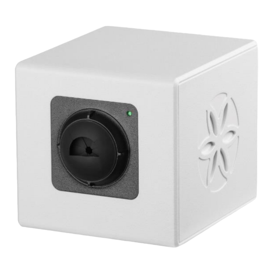
Page 8: Standard Set Of The Bio-Well Gdv Camera 3.0
Bio-Well 1.0 device front and back view: Bio-Well 2.0 device front and back view: The only difference between 2.0 and 1.0 Bio-Well device external design is presence of the ventilator button at the back of the 2.0 device. Bio-Well Company... - Page 9 ON, but device is not recognized by the operating system of your computer. Check the drivers installation or reinstall the software while deactivating antivirus and firewall. Turn off the Bluetooth on your computer – it may conflict with the Bio-Well device. Bio-Well Company www.bio-well.com...
- Page 10 – contact local Bio-Well representative. 2. Place for the finger insert or calibration cylinder insert. 3. USB cable socket: USB-B for Bio-Well 1.0 and 2.0 devices, USB-C for Bio-Well 3.0 device. 4. “Ground” or “Earth” socket. Used for connection of the calibration cable during calibration of 1.0 and 2.0 devices.
-
Page 11: Getting Started
Once the installation process is completed, and a subscription has been purchased (www.bwacc.com), connect one end of the included USB cable to the rear of the Bio-Well GDV Camera device, and the other end to the computer. - Page 12 NB! If you need to change the language of the interface in the Bio-Well software, click “Account” and select “Log out”, and you will get back to the login window (pic. 1) to select another language. Each Bio-Well GDV Camera device requires a subscription account (Login/Password) by default.
-
Page 13: Software Interface
Pic. 2. Main screen of the Bio-Well Software. In the top bar of the window you can find the version of the Bio-Well Software that you are logged in and in brackets you can find the expiry date of your paid subscription. - Page 14 Pic. 3. Recent scans interface. - opens a list of all Scans received by the User from other Bio-Well Software Users organized according to the time sequence. Each line shows: name of the Card, login name of the User who have sent the Scan, icon of the type of the Scan, and date + time of the Scan.
- Page 15 If you don’t want to upload some of the Scans (Experiments) click the “X” sign on the right side of the Scan line. To start the upload please click the green “Upload” button. Experiments will be uploaded to your database on the server. Bio-Well Company www.bio-well.com...
- Page 16 Camera device and retrieving general technical information about the Bio-Well GDV Camera device and it’s functioning. Pic. 6. Calibration interface. For calibration you need a Calibration Pack (it is supplied with every Bio-Well device). Prepare the device for the calibration and click “Start”. Detailed instructions are given at the end of this manual.
- Page 17 Click the “i” button in the top right corner to see the technical information about the connected Bio-Well GDV Camera device: Pic. 9. Technical information window. When the calibration procedure is finished you will see the pop-up window with notification “Calibration complete” where you should click “OK”, and you will be automatically redirected to the Database screen.
- Page 18 Software log is intended for the technical support by the Authorized Distributors of the Bio-Well company and is password protected. NB! If you need to change the language of the Bio-Well Software interface you have to log out from the account, select a language, input password and log in again.
-
Page 19: Cards List
Pic. 10. Main screen of the Bio-Well Software. In the right side of the control panel you can find buttons for creating new scans. First you need to select the needed Card in the Cards list and then click one of the scans that you want to make: “Full scan”, “Stress scan”, “One Finger”... - Page 20 Card. Name of the Card will become colored according to the color of the label. To erase previously assigned label from the Card: select a Card, click on the button and select “Empty label”. To create new labels select “Edit labels...” line. New window will be displayed (pic. 13). Bio-Well Company www.bio-well.com...
- Page 21 (label names) – your list of Cards will be filtered accordingly to your selection. In example, if you select label “1st group” then you will see only Cards with this label in the list. Bio-Well Company www.bio-well.com...
-
Page 22: Scans List
Selecting scans and experiments here you can send them to Comparison by clicking button. Also, you can send any scan or experiment to other Bio-Well User if you know his/her Login by selecting the Scan and clicking button. A pop-up window will be displayed: Pic. - Page 23 If you have made a mistake in the Login name – you will see error window: Pic. 19. Error sending a Scan to another Bio-Well User. If this scan was already previously sent to the specified User – you will also see the error window.
-
Page 24: Creating A New Scan/Experiment
Scan was made. Creating a new Scan/Experiment Right part of the Main screen of the Bio-Well Software is devoted to the representation of the results and creating new Scans. In the right top corner you can click “Full Scan”, “Stress Scan”, “One Finger” or “Environment”... -
Page 25: Rules Of Capturing Fingers
If the fingers are hot or sweaty, or the humidity is high in the place where you work with your Bio-Well 3.0 device – turn the ventilator ON. You don’t need to turn it OFF – it will be turned off automatically after 1 minute. Ventilator of BW 3.0 device can be turned ON before the start of any Scan –... - Page 26 Pic. 23. 3 – finger is skewed; 4 – nail is touching the electrode. Pic. 24. 5 – too high pressure (inscribed ellipse is too big [depends on the size of the actual finger]); 6 – finger is rotated (program can't correctly derive where is the top of the finger). Bio-Well Company www.bio-well.com...
- Page 27 If you see any external light on the GI or you want to correct the position of the blue line – double click on any place of the image or click the sign in the top right corner of a GI. A new pop-up window will be displayed (pic. 27). Bio-Well Company www.bio-well.com...
- Page 28 “Edit ellipse” button in the top right corner. Design of the window will be changed and you will see ellipse, blue line and 4 yellow dots for rotation of the ellipse together with the blue line (see picture below). Pic. 27.1. Editing ellipse of the image. Bio-Well Company www.bio-well.com...
-
Page 29: Conducting A "Full Scan
Bio-Well Software program. If Bio-Well server is not able to define the top of the finger it will not show the blue horizontal line on the GI and red exclamation mark will be displayed (see pic. - Page 30 Do not leave any external noise pixels on the images as they will spoil the calculation of results! For the users of old GDV camera models it is still possible to import images captured not inside the Bio-Well software by clicking the button and specifying the folder with needed BMP files.
-
Page 31: Full Scan" Results
Select any “Full Scan” (marked with sign) from your database. Results of the Scans that you select in the Scans list are automatically downloaded from the Bio-Well Server. When you select multiple Scans at a time by using CTRL or SHIFT buttons on your keyboard –... - Page 32 – look at the bottom part of the screen where the actual sector of the finger and glow parameters are represented. Left-clicking on any sector will open a new window with the finger on which this sector is present (pic. 31). Bio-Well Company www.bio-well.com...
- Page 33 Pic. 31. Selected sector preview in a separate window. If you right click with your mouse on the glow around the human figures — magnifying effect will be applied (pic. 32). Pic. 32. Right-click to use the loupe. Bio-Well Company www.bio-well.com...
- Page 34 2 parameters and name of chakra in the Description field (at the bottom of the screen) (pic. 33). Pic. 33. Chakras tab view. Click on a particular Chakra to see the full standard description (pic. 34). Bio-Well Company www.bio-well.com...
- Page 35 (pic. 35). Pic. 35. Balanced view of chakras. The “Create Music” button generates a unique music file which may be saved to be used with a Bio-Cor device. See Bio-Cor manual for more information. Bio-Well Company www.bio-well.com...
- Page 36 If you want to save the current image of the Yin Yang meridian – click button in the top right corner and specify the folder in which you want to save it. Pic. 36. Yin Yang meridians tab. Bio-Well Company www.bio-well.com...
- Page 37 (click “See optimal area diagram” button to see it (pic. 39)). Not all the organs and systems are represented on this diagram. Actual ratio value for each sector is represented in red colored numbers at the outer border of the diagrams. Bio-Well Company www.bio-well.com...
- Page 38 Borders of green zone are different for different age groups: - Below 20 years upper border is 1.3; - From 20 to 60 years upper border is 1.0; - More than 60 years upper border is 0.6. Bio-Well Company www.bio-well.com...
- Page 39 Intensity of the Glow. To see the relative assessment of the Intensity parameter influence click “Show Area diagram” button and see the gap between the overlaid diagrams (absolute value of the gap has no meaning, only relative comparison can be applied) (pic. 41). Bio-Well Company www.bio-well.com...
- Page 40 Pic. 40. Energy diagram tab view with optimal diapason activated. Pic. 41. Energy diagram and Area diagram overlaid. Bio-Well Company www.bio-well.com...
- Page 41 Y-axis is for Energy value. If you want to save the image of the Balance graph – click button in the top right corner and specify the folder in which you want to save it. Bio-Well Company www.bio-well.com...
- Page 42 If you want to save any image from the Organs Energy tab – select the system and click button in the top right corner and specify the folder in which you want to save it. Pic. 44. Organs and systems list. Bio-Well Company www.bio-well.com...
- Page 43 Here you can see actual intersection of GIs according to the acupuncture points concept and more than 20 years of clinical studies and research. Clicking on any GI will open a separate window with a larger view of the GI and calculated parameters (pic. 47). Bio-Well Company www.bio-well.com...
- Page 44 Pic. 46. Fingers tab view. Pic. 47. Pop-up window with GI of a finger and its parameters. Bio-Well Company www.bio-well.com...
- Page 45 - print the current image; - turn on/off the grey-scale coloring mode (original image); - turn on/off the standard 9-grades coloring mode (selected by default); - turn on/off sectors intersection scheme; - turn on/off inner and outer contour lines. Bio-Well Company www.bio-well.com...
- Page 46 Pic. 49. Grey-scale mode of the image. Grey-scale is the original image that is used for calculation of all the parameters in the Bio-Well Software. On the right side you can see the list of all parameters calculated for each GI of finger and each sector.
- Page 47 Pic. 50. Spectrum of the Glow Image of one finger. Left part of the spectrum is cut as it is related to the background pixels of the CCD matrix of the Bio-Well GDV Camera device. These pixels are visible only on the images while...
- Page 48 “Analyze” button all these pixels are deleted and only the pixels related to the Glow Image are left. Pic. 51. Isoline of the Glow Image. Isoline of the GI is not used for interpretation, it is more technical data. Pic. 52. Parameters of the whole GI and its sectors. Bio-Well Company www.bio-well.com...
- Page 49 In order to see brief description of the parameters click “Description” button in the bottom right corner (pic. 53). Pic. 53. Description of parameters with norms. Only those parameters that have norms are colored in the table according to the standard coloring grid (pic. 52). Bio-Well Company www.bio-well.com...
- Page 50 It is opened in a separate window. You can select the modules that you want to be included in the report by marking them (pic. 54). Pic. 54. Window for selecting the modules in the report. Pic. 55. Automatic report template. Bio-Well Company www.bio-well.com...
- Page 51 Report file is automatically divided into pages. It is possible to customize header and footer of the automatic report, and add page numbers. Click on the button to enter page setup menu (pic. 56-57). Pic. 56. Common settings of the page setup. Bio-Well Company www.bio-well.com...
- Page 52 Both header and footer should be loaded in either JPG or PNG file format (pic. 58). Click “Load” button to select the file. You can always restore the default settings and parameters by clicking “Restore Defaults” button. Bio-Well Company www.bio-well.com...
- Page 53 Pic. 58. Selecting the JPG or PNG file for header or footer in the page setup. If you add your company’s header and footer once – they will be applied to all further automatic reports that you will create in this Bio-Well Account. Export to CSV tab...
-
Page 54: Conducting A "Stress Test" Scan
(pic. 59). Pic. 59. Interface for conducting a “Stress Test” Scan. If your Bio-Well GDV Camera device is already connected to your computer – then you can conduct a Scan. You can cancel the scanning process at any moment by clicking “Cancel”... -
Page 55: Stress Test" Scan Results
Scans that you select in the Scans list are automatically downloaded from the Bio-Well Server. When you select multiple Scans at a time by using CTRL or SHIFT buttons on your keyboard – results of all the selected Scans are going to be downloaded one-by-one. -
Page 56: Conducting A "One Finger" Scan
Select a Card in which you want to make a “One Finger” Scan and click “One Finger” button in the right top corner of the main screen to create a new Scan. Special interface will be displayed (pic. 62). In this mode you can capture one selected finger several times. Bio-Well Company www.bio-well.com... -
Page 57: One Finger" Scan Results
Maximum is 100. If you don’t like any of the images click the black cross at the top of the image to delete it. Click “Analyze” button once you are satisfied with the quality of all captured images. “One Finger” Scan results Select “One Finger” Scan (marked with sign) from your database (pic. 63). Bio-Well Company www.bio-well.com... - Page 58 It is also possible to save images and one of the graphs in one move – click the button and specify the folder in which you want to save them. Bio-Well Company www.bio-well.com...
- Page 59 – just click “Export to CSV” button, specify a name of the file and a folder in which you want to save it. If you want to save any graph – click button in the top right corner and specify the folder in which you want to save it. Bio-Well Company www.bio-well.com...
-
Page 60: Conducting An "Environment" Scan
Special interface will be displayed (pic. 65A). Pic. 65A. Interface for conducting an “Environment” Scan. Place metal cylinder insert on the Bio-Well glass electrode and connect an external electrode wire with “banana” jack to it. Bio-Well Company produces three types of external electrode: Bio-Well Glove, Sputnik Sensor and Water Sensor. - Page 61 00:00 again, and you will be able to add labels by clicking “Add Label” button. Labels may be added during readings. Just assign a name to every Label that you add and click “OK”. Bio-Well Company www.bio-well.com...
- Page 62 Added labels will be displayed on the graphs as red lines. You can switch the “Full screen” mode by clicking such button at the top right corner of the screen (pic. 69). Bio-Well Company www.bio-well.com...
- Page 63 “OK” (see pic.70). Pic. 70. Setting up manually scale of the Y axis on the graph. In the bottom of the screen you can see the “Add a note” field, where you can add any notes about this experiment. Bio-Well Company www.bio-well.com...
-
Page 64: Environment" Scan Results
Clicking “Stop” button and clicking “Yes” in the pop-up window will save the data on the computer if Offline, or on the server if Online. In Online mode Scan will be automatically processed on the Bio-Well Server and downloaded to your computer – you will see the result on your screen. - Page 65 (dots) that you want to cut from the graph (the diapason will be colored in green). - click this button to undo last change that you have made. Bio-Well Company www.bio-well.com...
- Page 66 - Save as CSV: save all the experiment with all 4 parameters calculated to a CSV file format. - click these buttons to maximize or minimize the scale of the X axis. - click these buttons to maximize or minimize the scale of the Y axis. Bio-Well Company www.bio-well.com...
- Page 67 Change any of the available parameters and click “OK” to apply them. As soon as you have made all the preparations to statistical analysis – click “Statistics” button – a new window will be opened (pic. 76). Pic. 76. Statistics window for the “Environment” Scan. Bio-Well Company www.bio-well.com...
- Page 68 4 parameters for the periods between the labels that you have added. The Bio-Well Server will calculate parameters for all labeled intervals and parametric / non-parametric statistical values. Every interval is compared with the previous interval (pic. 77).
-
Page 69: Comparing Scans
Results of the Scans that you select in the Scans list are automatically downloaded from the Bio-Well Server. Select multiple Scans at a time that you want to compare by using “CTRL“ or “SHIFT” buttons on your keyboard – results of all the selected Scans are going to be downloaded one-by-one. - Page 70 Parameters from this tab are present in another way on the “Graphs” tab: “Left”, “Front” and “Right” projection Energy values, and Chakras Alignment parameter are shown (pic. 79). On the “Energy Field” tab you will see the outer contour comparison. Bio-Well Company www.bio-well.com...
- Page 71 “Save as picture” button in order to save the graphs or “Export to CSV” button if you want to analyze the parameters in any program for statistical analysis (Microsoft Excel, LibreOffice Calc, Algorithm, etc.). Bio-Well Company www.bio-well.com...
- Page 72 Third quartile (Q3 / 75th Percentile – the ceiling of the box): is also known as the upper quartile qn(0.75) and is the middle value between the largest number (not the maximum) and the median of the dataset.[ Bio-Well Company www.bio-well.com...
- Page 73 Comparing “Environment” Scans If you are comparing “Environment” Scans then you will be able to compare the data in two variants: Plots (pic. 83) and Charts (pic. 84). Bio-Well Company www.bio-well.com...
- Page 74 Intensity, Energy and Entropy parameters (pic. 84). These values are calculated from the whole time of the experiment. Labels are not taken into consideration during comparison of “Environment” Scans. To return back to the list of Scans selected for comparison click “Back” button. Bio-Well Company www.bio-well.com...
-
Page 75: Offline Mode
Bio- Well Server. Offline Scans are saved as BDF files on the computer’s drive. When next logged in online, an “Upload” button will appear; click it to send the data to the Bio-Well Server to be processed. Bio-Well Company... -
Page 76: Previous Gdv Readings
Software. A Card must first be created to be associated with the data to be imported. Remember that your account is limited to 1 ChipID by default, so Bio-Well Software will not allow you to use images taken by the devices with ChipIDs not associated with your account. -
Page 77: Calibration Guidelines
1. Connect the USB cable to the Bio-Well GDV Camera device and computer. 2. Put the Bio-Well GDV Camera device on the white stand as it is shown on the pic. 85. If you have positioned it correctly – you should easily see the label with the serial number on the bottom surface of the Bio-Well GDV Camera device. - Page 78 7. Connect the other end of the grounding cable to the port («ground/earth») located at the rear of the Bio-Well GDV Camera device (pic. 86). Pic. 86. Bio-Well GDV Camera device 1.0 on the calibration stand.
- Page 79 If parameters of the Glow are not in the normal region (established on the Bio-Well server) — then server will send a command to the Bio-Well GDV Camera device to change the voltage of the impulses accordingly, and restart the calibration cycle again automatically after 30 seconds interval.
- Page 80 6. Connect the other end of the grounding cable to the port («ground/earth») located at the rear of the Bio-Well GDV Camera device (pic. 87). Pic. 87. Bio-Well GDV Camera 2.0 prepared for calibration. 7. Click “Start” button and wait for 20 seconds. Software will calibrate the device automatically.
- Page 81 Bio-Well Company www.bio-well.com...
Need help?
Do you have a question about the GDV Camera 3.0 and is the answer not in the manual?
Questions and answers