Panasonic KX-TGA670B - Cordless Extension Handset Service Manual
Hide thumbs
Also See for KX-TGA670B - Cordless Extension Handset:
- Operating instructions manual (21 pages)
Table of Contents
Advertisement
Telephone Equipment
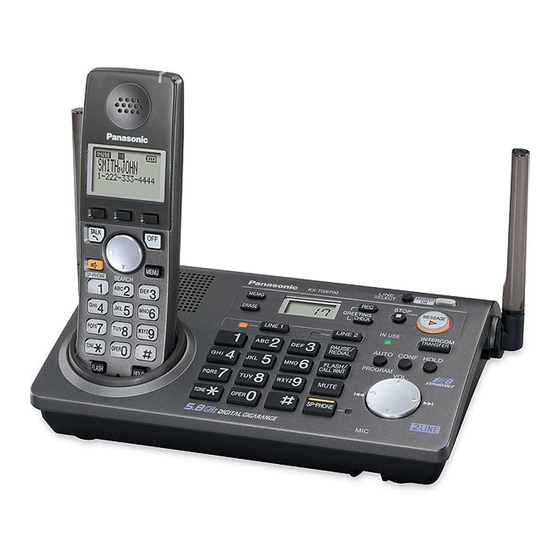
KX-TG6700B
KX-TG6702B
KX-TGA670B
5.8 GHz Expandable Digital Cordless
Answering System
5.8 GHz Expandable Digital Cordless
Answering System with Two Handsets
Black Version
(for U.S.A.)
© 2006 Panasonic Communications Co., Ltd. All
rights reserved. Unauthorized copying and distribu-
tion is a violation of law.
ORDER NO. KM40604038CE
F12
Advertisement
Table of Contents
Troubleshooting

Related Manuals for Panasonic KX-TGA670B - Cordless Extension Handset


Summarization of Contents
Safety Precautions
For Service Technicians
Precautions for service technicians regarding static electricity.
Technical Descriptions
FHSS Description
Explanation of Frequency Hopping Spread Spectrum system.
Base Unit Operation
Explanation of DSP, Flash Memory, and Power Supply circuit operations.
Handset Operation
Explanation of Handset DSP, RF part, EEPROM, Power Supply, Charge.
RF Part Operation
Explanation of RF part functions including power supply and circuits.
Charger Unit Operation
Explanation of the charger unit's circuit operation.
Signal Route
Description of signal paths throughout the system.
Location of Controls and Components
Controls and Displays
Identification of controls and display items for Base Unit and Handset.
Installation Instructions
Setting Up the Base Unit
Connecting the AC adaptor and telephone line cord.
Setting Up the Handset
Battery Installation/ Replacement
Procedure for installing or replacing the handset battery.
Operation Instructions
Symbols and Settings
Explanation of symbols and how to use programmable settings.
Test Mode
Adjustment and Test Mode Flow Chart
Flowcharts for Base Unit test modes like Test Burst and RX-CW.
Service Mode
How to Clear User Setting
Procedure to reset units to factory settings by erasing user data.
Troubleshooting Guide
Troubleshooting Flowchart
Step-by-step guide to diagnose and resolve common unit problems.
Error Message Table
Table listing error messages and their corresponding remedies.
Check the RF part
Steps to identify defective parts within the RF section.
RF Check Flowchart
Flowchart for performing RF checks on the unit.
Disassembly and Assembly Instructions
Disassembly Procedures
Step-by-step instructions for disassembling Base Unit, Handset, and Charger.
Measurements and Adjustments
Things to Do after Replacing IC
Procedures for checking and adjusting ICs after replacement.
Schematic Diagrams
Base Unit Schematics
Schematic diagrams for Base Unit Main, RF Part, and Operation.
Handset Schematics
Schematic diagrams for Handset Main, RF Part.
Charger Unit Schematic
Schematic diagram for the Charger Unit.
Printed Circuit Board Layouts
PCB Layouts
Component and flow solder views for Base Unit, Handset, and Charger PCBs.
Appendix Information
IC Pin Data and Terminal Guides
CPU pin data for Base Unit/Handset and IC terminal guides for RF parts.
Exploded View and Replacement Parts List
Parts Identification and Lists
Exploded views and lists of parts for Base Unit, Handset, Charger, and accessories.
Need help?
Do you have a question about the KX-TGA670B - Cordless Extension Handset and is the answer not in the manual?
Questions and answers