Table of Contents
Advertisement
Quick Links
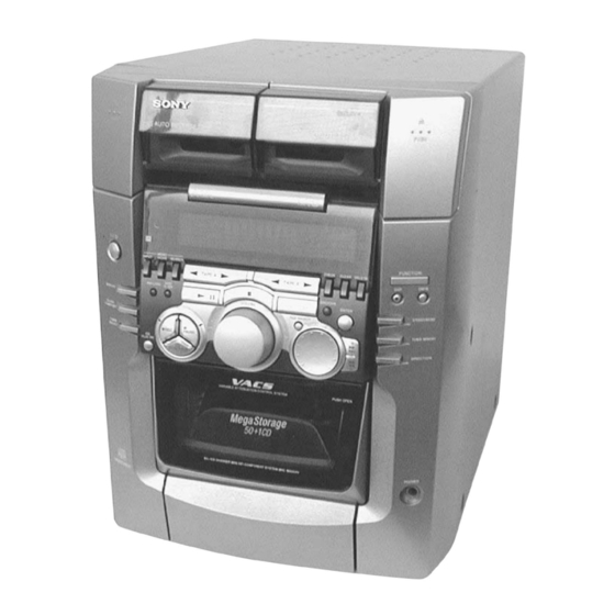
SERVICE MANUAL
• MHC-M500AV is composed of following models.
As for the service manual, it is issued for each component
model, then, please refer to them.
COMPONENT MODEL NAME
COMPACT DISC DECK RECEIVER SYSTEM
FRONT SPEAKER
SPEAKER
SPEAKER
SYSTEM
PACK
SUPER WOOFER
SPECIFICATIONS
General
Power requirements:
120 V AC, 60Hz
Power consumption:
210 watts
Dimensions (w/h/d):
Approx. 280 x 373 x 468 mm
Mass:
Approx. 11.0 kg
Supplied accessories:
AM loop antenna (1)
Remote commander (1)
Batteries (2)
FM lead antenna (1)
Speaker cords (2)
Center speaker pads (4)
Monaural connecting cord (1)
Design and specifications are subject to change without notice.
9-929-284-11
MHC-M500AV
CENTER SPEAKER
SS-RC175D
REAR SPEAKER
Sony Corporation
Audio Entertainment Group
HCD-M500AV
SS-M500AV
SS-CT175D
SS-RS175D
SA-W17
PARTS LIST
Part No.
Description
ACCESSORIES & PACKING MATERIALS
*******************************
1-476-193-11
COMMANDER, STANDARD (RM-SX5)
1-501-374-11
ANTENNA, LOOP
1-501-659-41
ANTENNA (FM)
1-769-433-11
CORD, SPEAKER (10m) (SS-RS175D)
1-751-598-11
MONAURAL CONNECTING CORD ( 2m) (SA-W17)
4-227-898-11
MANUAL, INSTRUCTION (ENGLISH)
4-210-254-01
CUSHION (FOOT)
4-981-643-21
BATTERY COVER (FOR RM-SX5)
COMPACT COMPONENT SYSTEM
US Model
Remark
2000E001613-1D
Printed in Japan ©2000.5
Published by HA Quality Assurance Dept.
Advertisement
Table of Contents

Related Manuals for Sony MHC-M500AV


Summarization of Contents
SPECIFICATIONS
General System Specifications
Details power requirements, consumption, dimensions, and mass of the system.
SERVICING NOTES AND SAFETY
Safety Check-out and Leakage Testing
Outlines safety checks, including AC leakage testing, and general cautions for laser product safety.
Servicing Precautions
Provides precautions for handling optical parts, chip components, and circuit boards during servicing.
SECTION 2 DISASSEMBLY
Case and Front Panel Disassembly
Procedures for removing the outer case and the front panel section, detailing screws and connectors.
Internal Component Disassembly
Steps for disassembling internal components like the door, back panel, main board, and CD mechanism deck.
SECTION 3 TEST MODE
System Test Modes Overview
Details various test modes including cold/hot reset, CD initial, line test, memo clear, GC test, and aging mode.
SECTION 4 MECHANICAL ADJUSTMENTS
Tape Mechanism Torque Measurements
Lists torque specifications for various tape mechanism modes like FWD, REV, FF/REW, and tension adjustments.
CD Mechanism Disc Sensor Alignment
Procedure for aligning the disc sensor in the CD mechanism using an oscilloscope and specific test signals.
SECTION 5 ELECTRICAL ADJUSTMENTS
Deck Section Electrical Adjustments
Procedures for deck section electrical adjustments like azimuth, tape speed, and playback level.
SECTION 6 DIAGRAMS
CD Section Block Diagram
Illustrates the functional blocks and signal paths within the CD section of the system.
BD Section Schematics
Provides the detailed electronic schematic for the BD section, including ICs, transistors, and connections.
BD Board IC Pin Function Description
Details the function of each pin for IC101 on the BD board, crucial for troubleshooting and understanding signals.
SECTION 7 EXPLODED VIEWS
Exploded Views of Major Assemblies
Visual breakdowns of case, front panel, mechanisms, and speakers for part identification.
SECTION 8 ELECTRICAL PARTS LIST
Component Lists for Key Boards
Detailed lists of electronic components for BD, Cassette, Main, and Panel boards.
Need help?
Do you have a question about the MHC-M500AV and is the answer not in the manual?
Questions and answers