
Related Manuals for 1 Sound SUB310

Summary of Contents for 1 Sound SUB310
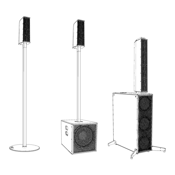
- Page 1 Stacked and Pole-Mounted Deployments of the Tower System 1 SOUND INC – 34 Apple Street, Tinton Falls, NJ 07724 – +1-732-798-9900 – www.1-sound.com...
-
Page 2: Table Of Contents
TOWER LCC44................4 Installing the Tower Tube Mount directly on LCC44..... 35 TOWER LCC44 Specifications..........4 Mounting LCC44 on Active Speaker Tube using the Tower Tube Mount ................... 36 TOWER LCC84................4 Installing the Tower Tube Mount on a Tower Rigging System TOWER LCC84 Specifications..........4... - Page 3 CONTENTS | iii Procedures..................80 Mounting Rigging plate on CSUB610........80 Installing Outriggers on the CSUB610........81 Installing Rigging Plate on LCC44/84........85 Coupling LCC44/84 units to CSUB610 using Tower Rigging System...................86 Coupling Stacked LCC84 or LCC44 units via the Tower Rigging System...................88...
-
Page 4: Chapter 1. Speaker Models
Cardioid Column Line Array Enclosure Figure 1. LCC44 with Tower Rigging System (left), and without. Tower LCC44 is a cardioid line array element featuring designed to be compact, high powered and array-able. The enclosure features Clarity Technology©, a proprietary high frequency technology built around four coaxial transducers each composed of a 4"... -
Page 5: Sub310
This bass enclosure offers the sound of a double 18" subwoofer in omni mode. CSUB610 is designed to accept proprietary Tower Rigging SUB310 Specifications System plates for stacking multiple LCC44 columns directly on the cabinet, as well as a recessed cup for square-section Active Speaker Description Passive line source subwoofer, ultra slim with tetracoil tech... -
Page 6: Csub210
Active Speaker Tube, allowing the deployment of an woofer in the rear. It is capable of operating in cardioid, sub cardioid (end LCC44 unit in a sub/satellite configuration. It is ideal for applications in fire) and omnidirectional modes, and designed for positioning parallel or restaurants and lounges, fitting in tight spaces, as well as for residential perpendicular to walls, or even low-profile horizontal deployment. -
Page 7: Chapter 2. Accessories
Figure 9. Tower Tube Mount The Tower Tube Mount enables a Tower loudspeaker to be coupled with the proprietary Active Speaker Tubes for deployment of LCC44 or LCC84 cardioid column line array enclosures on a free-standing base or atop a SUB310 or CSUB610 subwoofer. -
Page 8: Active Speaker Tube & Base
It is available with a black or white finish. The kit includes: The Sub Pole Cup is made from 4 mm steel and fits in various 1 SOUND • The fully assembled Active Speaker Tube subwoofers in order to mount a satellite speaker enclosure. -
Page 9: Subwoofer Outriggers
| 2 - ACCESSORIES Subwoofer Outriggers Optional stabilizing legs for subwoofer models SUB310 and CSUB610 Figure 13. Subwoofer Outriggers The Subwoofer Outrigger set is designed to be mounted to the SUB310 or SUB610 subwoofer models to improve stability when these are deployed vertically on the floor. -
Page 10: Chapter 3. Deploying Lcc44 On An Active Speaker Tube
Restriction: Do not install a loudspeaker or any accessory near any open flame or heat source. Products/accessories involved To deploy an LCC44 enclosure on an Active Speaker Tube with Base you will need the following: Critical information •... -
Page 11: Installing The Tower Tube Mount Directly On Lcc44
| 3 - DEPLOYING LCC44 ON AN ACTIVE SPEAKER TUBE & BASE Figure 15. The Active Speaker Tube base. Figure 18. The fully Assembled Active Speaker Tube and Base • Place the round base of the Active Speaker Tube on a flat surface so that it rests flat and the M20 threaded nut at the center protrudes above. - Page 12 Figure 20. Removing screws from Tower Tube Mount attachment points. • Invert the LCC44 enclosure and use a 4 mm Allen wrench or hex driver to remove the two M6×16 mm screws from the rigging points indicated above on the bottom side of the cabinet. Put these aside, as they will be used to mount the Tower Tube Mount.
-
Page 13: Mounting Lcc44 On Active Speaker Tube Using The Tower Tube Mount
| 3 - DEPLOYING LCC44 ON AN ACTIVE SPEAKER TUBE & BASE • Make sure that the 95 cm Active Speaker Tube is properly Figure 22. Mounting Tower Tube Mount to bottom of LCC44 installed in the CSUB610 or SUB310 (either model equipped... - Page 14 STACKED AND POLE-MOUNTED DEPLOYMENTS OF THE TOWER SYSTEM • Lower the LCC44 enclosure and allow the Active Speaker Tube to slide into the Tower Tube Mount, making sure that it does not catch or bind as it enters. It should stop firmly when the Tube arrives at the top of the Mount, with the bottom of the Tower Tube Mount coming to 2 cm above the top SpeakOn connector.
-
Page 15: Chapter 4. Deploying Lcc44 On An Active Speaker Tube Atop
Restriction: Do not install a loudspeaker or any accessory near any open flame or heat source. Products, accessories and tools required To deploy an LCC44 enclosure as a satellite on a CSUB610 bass unit using an Active Speaker Tube you will need the following: •... -
Page 16: Procedures
90° outriggers are installed at the rear. Naturally, this configuration can be used with omnidirectional presets on the subwoofer, as well, but only when the LCC44 or LCC84 units are coupled parallel to the CSUB610, with all the forward grilles facing the same direction. - Page 17 | 4 - DEPLOYING LCC44 ON AN ACTIVE SPEAKER TUBE ATOP CSUB610 Figure 29. Raising the leveling feet of the Figure 31. Configuring the outriggers on CSUB610 Outriggers. for parallel deployment of LCC44/84 units (bottom view). • Before installation, on each of the four Outriggers, raise the leveling feet by screwing them in completely.
- Page 18 STACKED AND POLE-MOUNTED DEPLOYMENTS OF THE TOWER SYSTEM Figure 33. Aligning forward Outrigger on CSUB610 Figure 35. Aligning rear Outrigger on CSUB610 (side view) (side view). • Using a 5 mm hex wrench, fully tighten the countersunk M8 screw into the rigging point. •...
- Page 19 | 4 - DEPLOYING LCC44 ON AN ACTIVE SPEAKER TUBE ATOP CSUB610 Figure 38. Leveling CSUB610 side-to-side – CAUTION example. Tipping Hazard The Subwoofer Outriggers can be used to apply minor adjustments to the leveling of the SUB310 or CSUB610 subwoofer units. DO NOT install...
-
Page 20: Installing Active Speaker Tube To Csub610
Figure 41. Active Speaker Tube installed in CSUB610. In order to deploy an LCC44 unit in a sub/satellite configuration atop a CSUB610 or SUB310 unit with the Sub Pole Cup installed, it is only necessary to insert the Active Speaker Tube into Pole Cup with the SpeakOn connectors facing the rear of the subwoofer cabinet and assure that it is firmly seated in the Pole Cup. -
Page 21: Installing The Tower Tube Mount Directly On Lcc44
Mount. A magnetized hex driver can facilitate this. • Invert the LCC44 enclosure and use a 4 mm Allen wrench or hex driver to remove the two M6×16 mm screws from the rigging points indicated above on the bottom side of the cabinet. -
Page 22: Mounting Lcc44 On Active Speaker Tube Using The Tower Tube Mount
Tube Mount above the Active Speaker Tube and align it in the desired direction. Though not obligatory, this will generally be with the rear of the LCC44 towards the rear of the subwoofer, where the connectors are located. Figure 46. Mounting LCC44 equipped with Tower Tube Mount to Active Speaker Tube. -
Page 23: Installing The Tower Tube Mount On A Tower Rigging System Plate
| 4 - DEPLOYING LCC44 ON AN ACTIVE SPEAKER TUBE ATOP CSUB610 • Lower the LCC44 enclosure and allow the Active Speaker Tube Figure 49. Tower Tube Mount on Rigging plate for to slide into the Tower Tube Mount, making sure that it does not 0°, -3°... -
Page 24: Installing Rigging Plate On Lcc44/84
• Using a 4 mm hex driver, tighten the two screws very firmly. Installing Rigging Plate on LCC44/84 In order to couple LCC44 or LCC84 units to each other, directly to a subwoofer, or to allow for variable tilt angles of the enclosure in sub/... -
Page 25: Coupling Tower Tube Mount And Lcc44 Using The Tower Rigging System
(with the Tube Mount installed) with respect The plate should be perfectly flush with the cabinet at every to the LCC44. This done, it is possible to fix the tilt angle of the point and there should be no movement possible. -
Page 26: Mounting Lcc44 On Active Speaker Tube Using The Tower Rigging System
Tube Mount above the Speaker Tube and align it in the desired direction. Though not obligatory, this will generally be with the rear of the LCC44 towards the rear of the subwoofer, where the connectors are located. • When the required holes are perfectly aligned, take the other M10×100 ball-lock pin supplied with the rigging plates and... - Page 27 Though it is preferable to set the tilt angle of the enclosure before mounting the LCC44 atop the Active Speaker Tube, it is possible to adjust the tilt angle of the enclosure using the Tower rigging System when it is already mounted on the Speaker Tube.
- Page 28 Mount in +3°,0°, -3° configuration. Risk of Hand Injury When adjusting the tilt angle of an LCC44 or the splay angle between two units, do not allow your fingers to enter the space between the two rigging plates or any of the holes.
-
Page 29: Chapter 5. Deploying Lcc44 On Active Speaker Tube Atop Sub310
Restriction: Do not install a loudspeaker or any accessory near any open flame or heat source. Products, accessories and tools required To deploy an LCC44 enclosure as a satellite on a SUB310 bass unit using an Active Speaker Tube you will need the following: •... - Page 30 STACKED AND POLE-MOUNTED DEPLOYMENTS OF THE TOWER SYSTEM • If the SUB310 has been previously configured for upright use Figure 65. Removing the Tower Rigging System Plate from SUB310. with the Tower Rigging System, it will still need to be inverted and the rubber feet re-installed on the opposite end before installing the Sub Pole Cup.
-
Page 31: Installing Outriggers On The Sub310
| 5 - DEPLOYING LCC44 ON ACTIVE SPEAKER TUBE ATOP SUB310 • Re-insert the screws that retained the plate into the four Figure 69. Installing the rubber feet on the SUB310. countersunk holes in the Sub Pole Cup, and thread them into the inserts below the cup. - Page 32 STACKED AND POLE-MOUNTED DEPLOYMENTS OF THE TOWER SYSTEM Figure 74. Removing rigging point screws from Figure 76. Aligning forward Outrigger on SUB310 SUB310 for the installation of the Sub Outriggers (side view) • Using a 5 mm hex wrench, fully tighten the countersunk M8 screw into the rigging point.
- Page 33 | 5 - DEPLOYING LCC44 ON ACTIVE SPEAKER TUBE ATOP SUB310 Figure 78. Aligning rear Outrigger on SUB310 (side CAUTION view). Tipping Hazard The Subwoofer Outriggers can be used to apply minor adjustments to the leveling of the SUB310 or CSUB610 subwoofer units. DO NOT install...
-
Page 34: Installing Active Speaker Tube On Sub310
Installing Active Speaker Tube on SUB310 In order to deploy an LCC44 unit in a sub/satellite configuration atop a CSUB610 or SUB310 unit with the Sub Pole Cup installed, it is only necessary to insert the Active Speaker Tube into Pole Cup with the SpeakOn connectors facing the rear of the subwoofer cabinet and assure that it is firmly seated in the Pole Cup. -
Page 35: Installing The Tower Tube Mount Directly On Lcc44
Figure 84. Active Speaker Tube installed in SUB310. • Invert the LCC44 enclosure and use a 4 mm Allen wrench or hex driver to remove the two M6×16 mm screws from the rigging points indicated above on the bottom side of the cabinet. Put these aside, as they will be used to mount the Tower Tube Mount. -
Page 36: Mount
Tube Mount Once the Tower Tube Mount has been correctly installed directly on an LCC44 enclosure, the enclosure can then be very simply mounted on an Active Speaker Tube, either atop a subwoofer in a sub/satellite configuration, or independently atop an Active Speaker Tube with base. -
Page 37: Installing The Tower Tube Mount On A Tower Rigging System Plate
Tube Mount above the Active Speaker Tube and align it in the desired direction. Though not obligatory, this will generally be Figure 90. LCC44 with Tower Tube Mount installed with the rear of the LCC44 towards the rear of the subwoofer, on Active Speaker Tube. where the connectors are located. -
Page 38: Installing Rigging Plate On Lcc44/84
• Using a 4 mm hex driver, tighten the two screws very firmly. Installing Rigging Plate on LCC44/84 In order to couple LCC44 or LCC84 units to each other, directly to a subwoofer, or to allow for variable tilt angles of the enclosure in sub/... -
Page 39: Coupling Tower Tube Mount And Lcc44 Using The Tower Rigging System
Rigging System mounting points. point and there should be no movement possible. If the LCC44 or LCC84 unit is being deployed as a single unit in a sub/satellite configuration atop a subwoofer using a Tower Tube Mount equipped with a rigging plate, or as a single unit (with no further... -
Page 40: Mounting Lcc44 On Active Speaker Tube Using The Tower Rigging System
(with the Tube Mount installed) with respect to the LCC44. This done, it is possible to fix the tilt angle of the speaker enclosure. - Page 41 Tube Mount above the Speaker Tube and align it in the desired direction. Though not obligatory, this will generally be with the rear of the LCC44 towards the rear of the subwoofer, where the connectors are located. • Lower the LCC44 enclosure and allow the Active Speaker Tube to slide into the Tower Tube Mount, making sure that it does not catch or bind as it enters.
- Page 42 Though it is preferable to set the tilt angle of the enclosure before mounting the LCC44 atop the Active Speaker Tube, it is possible to adjust the tilt angle of the enclosure using the Tower rigging System when it is already mounted on the Speaker Tube.
- Page 43 | 5 - DEPLOYING LCC44 ON ACTIVE SPEAKER TUBE ATOP SUB310 Figure 105. Adjusting tilt of LCC44 on Tower Tube Mount in +3°,0°, -3° configuration. Figure 106. Adjusting tilt of LCC44 on Tower Tube Mount in -3°,-6°, -9° configuration. • Before releasing the enclosure and allowing the assembly to...
-
Page 44: Chapter 6. Deploying Lcc44 On An Active Speaker Tube Atop Csub210
Figure 108. LCC44 deployed on the 95 cm Active Chapter 6. Deploying LCC44 on Speaker Tube atop CSUB210. an Active Speaker Tube atop CSUB210 Figure 107. LCC44 deployed on the 145 cm Active Speaker Tube atop CSUB210. Critical information Attention: This equipment is intended for installation by qualified professionals. -
Page 45: Products, Accessories And Tools Required
Restriction: Do not install a loudspeaker or any accessory near any open flame or heat source. Products, accessories and tools required To deploy an LCC44 enclosure as a satellite on a CSUB210 bass unit using an Active Speaker Tube you will need the following: •... -
Page 46: Installing Active Speaker Tube On Csub210
Installing Active Speaker Tube on CSUB210 In order to deploy an LCC44 unit in a sub/satellite configuration atop a CSUB210 unit with the Sub Pole Cup installed, it is only necessary to insert the 145 cm Active Speaker Tube into Pole Cup with the SpeakOn connectors facing the rear of the subwoofer cabinet and assure that it is •... - Page 47 Figure 116. Removing screws from Tower Tube Mount attachment points. • Invert the LCC44 enclosure and use a 4 mm Allen wrench or • Align the two countersunk holes in the Tower Tube Mount with hex driver to remove the two M6×16 mm screws from the rigging the threaded inserts in the rigging points from which the screws points indicated above on the bottom side of the cabinet.
-
Page 48: Mounting Lcc44 On Active Speaker Tube Using The Tower Tube Mount
Tube Mount above the Active Speaker Tube and align it in the desired direction. Though not obligatory, this will generally be with the rear of the LCC44 towards the rear of the subwoofer, where the connectors are located. Figure 119. Mounting LCC44 equipped with Tower Tube Mount to Active Speaker Tube. - Page 49 | 6 - DEPLOYING LCC44 ON AN ACTIVE SPEAKER TUBE ATOP CSUB210 • Lower the LCC44 enclosure and allow the Active Speaker Tube to slide into the Tower Tube Mount, making sure that it does not catch or bind as it enters. It should stop firmly when the Tube arrives at the top of the Mount, with the bottom of the Tower Tube Mount coming to 2 cm above the top SpeakOn connector.
-
Page 50: Chapter 7. Deploying Lcc44 On An Active Speaker Tube Atop Sub12
Figure 122. LCC44 deployed on the 95 cm Active Chapter 7. Deploying LCC44 on an Speaker Tube atop SUB12. Active Speaker Tube atop SUB12 Figure 121. LCC44 deployed on the 145 cm Active Speaker Tube atop SUB12. Critical information Attention: This equipment is intended for installation by qualified professionals. -
Page 51: Products, Accessories And Tools Required
Figure 124. Removing the cover plate for Sub Pole Cup installation. Products, accessories and tools required To deploy an LCC44 enclosure as a satellite on a SUB12 bass unit using an Active Speaker Tube you will need the following: •... -
Page 52: Installing Active Speaker Tube On Sub12
Installing Active Speaker Tube on SUB12 In order to deploy an LCC44 unit in a sub/satellite configuration atop a SUB12 unit with the Sub Pole Cup installed, it is only necessary to insert the 145 cm Active Speaker Tube into Pole Cup with the SpeakOn connectors facing the rear of the subwoofer cabinet and assure that it is firmly seated in the Pole Cup. -
Page 53: Installing The Tower Tube Mount Directly On Lcc44
• Lower the Active Speaker Tube to slide into the Sub Pole Cup, • Invert the LCC44 enclosure and use a 4 mm Allen wrench or making sure that it does not catch or bind as it enters. It should hex driver to remove the two M6×16 mm screws from the rigging... -
Page 54: Mounting Lcc44 On Active Speaker Tube Using The Tower Tube Mount
Tube Mount above the Active Speaker Tube and align it in the desired direction. Though not obligatory, this will generally be with the rear of the LCC44 towards the rear of the subwoofer, where the connectors are located. • Using a 4 mm hex driver, tighten the two screws very firmly. - Page 55 | 7 - DEPLOYING LCC44 ON AN ACTIVE SPEAKER TUBE ATOP SUB12 Figure 133. Mounting LCC44 equipped with Tower Figure 134. LCC44 with Tower Tube Mount installed Tube Mount to Active Speaker Tube. on Active Speaker Tube. • Physically assure the stability of the installation and that it will not tip using mild force applied in any direction at the highest point of the assembly.
-
Page 56: Chapter 8. Stacking Lcc84/Lcc44 On Sub310 Using The Tower Rigging System
Figure 136. LCC44 deployed atop SUB310 using the Chapter 8. Stacking LCC84/LCC44 Tower Rigging System. on SUB310 using the Tower Rigging System Figure 135. LCC84 deployed atop SUB310 using the Tower Rigging System. Critical information Attention: This equipment is intended for installation by qualified professionals. -
Page 57: Products/Accessories Involved
Procedures Mounting Rigging Plate on SUB310 In order to use the Tower Rigging System to deploy LCC44 or LCC84 units directly atop a SUB310 bass unit, the subwoofer unit must first be equipped with a Tower Rigging System plate. The compact SUB310 model is designed for use with either the Tower Rigging System or with the Active Speaker Tube. - Page 58 STACKED AND POLE-MOUNTED DEPLOYMENTS OF THE TOWER SYSTEM • Insert and thread the four rubber feet removed above into the Figure 142. Removing the screws from the inserts corresponding rigging points on the opposite end of the cabinet. for mounting the Tower Rigging System plate. Tighten these firmly by hand.
-
Page 59: Installing Outriggers On The Sub310
| 8 - STACKING LCC84/LCC44 ON SUB310 USING THE TOWER RIGGING SYSTEM Figure 144. Tightening the M6 screws on the Figure 146. Removing rigging point screws from installed Tower Rigging System plate. SUB310 for the installation of the Sub Outriggers •... - Page 60 STACKED AND POLE-MOUNTED DEPLOYMENTS OF THE TOWER SYSTEM Figure 148. Aligning forward Outrigger on SUB310 Figure 150. Aligning rear Outrigger on SUB310 (side (side view) view). • Using a 5 mm hex wrench, fully tighten the countersunk M8 screw into the rigging point. •...
- Page 61 | 8 - STACKING LCC84/LCC44 ON SUB310 USING THE TOWER RIGGING SYSTEM Figure 153. Leveling SUB310 side-to-side – CAUTION example. Tipping Hazard The Subwoofer Outriggers can be used to apply minor adjustments to the leveling of the SUB310 or CSUB610 subwoofer units. DO NOT install...
-
Page 62: Installing Rigging Plate On Lcc44/84
Installing Rigging Plate on LCC44/84 In order to couple LCC44 or LCC84 units to each other, directly to a subwoofer, or to allow for variable tilt angles of the enclosure in sub/ satellite configurations using the Tower Tube mount and Active Speaker Tube, the speaker enclosure needs to be equipped with Tower Rigging System plates. -
Page 63: Coupling Lcc44/84 To Sub310 Using Tower Rigging System
The plate should be perfectly flush with the cabinet at every point and there should be no movement possible. If the LCC44 or LCC84 unit is being deployed as a single unit in a sub/satellite configuration atop a subwoofer using a Tower Tube Mount... - Page 64 Attention: Until both lock pins have been completely inserted LCC84 or LCC44 units. and locked, maintain a grip on the LCC84 (or LCC44) unit. Figure 162. Setting a 0° tilt angle. • While maintaining a firm hold on the LCC84 enclosure, slide it to align the holes in the rigging plates closest to the front grille of both enclosures.
- Page 65 | 8 - STACKING LCC84/LCC44 ON SUB310 USING THE TOWER RIGGING SYSTEM • Once the second pin has been inserted and locked, the array Figure 163. Setting a -3° tilt angle. is configured. Before releasing the enclosure and allowing the...
-
Page 66: Chapter 9. Stacking Lcc44/84 Units On Csub610 In The Parallel Configuration Using The Tower Rigging System
Figure 167. One LCC44 and one LCC84 deployed Chapter 9. Stacking LCC44/84 atop CSUB610 using the Tower Rigging System in the parallel (cardioid sub) configuration. units on CSUB610 in the parallel configuration using the Tower Rigging System Figure 166. Three LCC44 enclosures deployed atop CSUB610 using the Tower Rigging System in the parallel (cardioid sub) configuration. -
Page 67: Products, Accessories And Tools Required
| 9 - STACKING LCC44/84 UNITS ON CSUB610 IN THE PARALLEL CONFIGURATION USING THE TOWER RIGGING SYSTEM For permanent or semi-permanent installation of the Tower WARNING Rigging System plates on the CSUB610 subwoofer, the use of medium-strength threadlocking compound is recommended on Tipping Hazard all user-installed screws. -
Page 68: Installing Outriggers On The Csub610
90° outriggers are installed at the rear. Naturally, this configuration can be used with omnidirectional presets on the subwoofer, as well, but only when the LCC44 or LCC84 units are coupled parallel to the CSUB610, with all the forward grilles facing the same direction. - Page 69 | 9 - STACKING LCC44/84 UNITS ON CSUB610 IN THE PARALLEL CONFIGURATION USING THE TOWER RIGGING SYSTEM Figure 173. Removing rigging point screws from Figure 175. Aligning forward Outrigger on CSUB610 CSUB610 for the installation of the Sub Outriggers (bottom view).
- Page 70 STACKED AND POLE-MOUNTED DEPLOYMENTS OF THE TOWER SYSTEM Figure 177. Aligning rear Outrigger on CSUB610 Figure 179. Lowering the Outrigger feet. (bottom view) • Align the mounting hole of the shorter 90° Outrigger with the bottom rigging point nearest the rear grille of the subwoofer and thread in the M8 screw into the threaded insert of the rigging point, making sure that the bottom bracket of the Outrigger fits firmly around the rubber foot of the subwoofer and flush with the...
- Page 71 | 9 - STACKING LCC44/84 UNITS ON CSUB610 IN THE PARALLEL CONFIGURATION USING THE TOWER RIGGING SYSTEM Figure 180. CSUB610 Side-to-side leveling. Figure 181. Leveling CSUB610 side-to-side – example. • With all four Subwoofer Outriggers installed, and each of the...
-
Page 72: Installing Rigging Plate On Lcc44/84
Installing Rigging Plate on LCC44/84 In order to couple LCC44 or LCC84 units to each other, directly to a subwoofer, or to allow for variable tilt angles of the enclosure in sub/ satellite configurations using the Tower Tube mount and Active Speaker Tube, the speaker enclosure needs to be equipped with Tower Rigging System plates. -
Page 73: Coupling Lcc44/84 Units To Csub610 Using Tower Rigging System
| 9 - STACKING LCC44/84 UNITS ON CSUB610 IN THE PARALLEL CONFIGURATION USING THE TOWER RIGGING SYSTEM Figure 185. Installing Tower Rigging System Plate WARNING to LCC44 Risk of Hand Injury When coupling or setting the splay angle between two... - Page 74 Attention: Until both lock pins have been completely inserted configurations are possible between the CSUB610 unit and and locked, maintain a grip on the LCC84 (or LCC44) unit. LCC84 or LCC44 units. • While maintaining a firm hold on the LCC84 enclosure, slide it Figure 190.
-
Page 75: Coupling Stacked Lcc84 Or Lcc44 Units Via The Tower Rigging System
| 9 - STACKING LCC44/84 UNITS ON CSUB610 IN THE PARALLEL CONFIGURATION USING THE TOWER RIGGING SYSTEM Figure 191. Setting a -3° tilt angle. Figure 194. Adding LCC44 units to a stacked array of CSUB610+LCC44. Figure 191. Setting a -6° tilt angle. - Page 76 STACKED AND POLE-MOUNTED DEPLOYMENTS OF THE TOWER SYSTEM Figure 195. Adding an LCC84 to a stacked array of Figure 196. Adding an LCC44 to a stacked array of CSUB610+LCC44. CSUB610+LCC84.
- Page 77 | 9 - STACKING LCC44/84 UNITS ON CSUB610 IN THE PARALLEL CONFIGURATION USING THE TOWER RIGGING SYSTEM • Take one of the M10×100 ball-lock pins supplied with the rigging Figure 197. Alignment of the Tower Rigging System plates, front view.
- Page 78 STACKED AND POLE-MOUNTED DEPLOYMENTS OF THE TOWER SYSTEM Figure 201. Setting a -3° tilt angle. Figure 203. Two LCC84/44 units fully coupled, 0° (parallel) splay angle shown. Figure 202. Setting a 3° tilt angle. • Once the second pin has been inserted and locked, the array is configured.
-
Page 79: Perpendicular Configuration Using The Tower Rigging System
Figure 205. Three LCC44 enclosures deployed atop Chapter 10. Stacking LCC44/84 CSUB610 using the Tower Rigging System in the perpendicular (omnidirectional sub) configuration. units CSUB610 perpendicular configuration using the Tower Rigging System Figure 204. LCC44 LCC84 deployed atop CSUB610 using the Tower Rigging System in the perpendicular (omnidirectional sub) configuration. -
Page 80: Products, Accessories And Tools Required
Mounting Rigging plate on CSUB610 rigging plate points. In order to use the Tower Rigging System to deploy LCC44 or LCC84 units directly atop a CSUB610 bass unit, the subwoofer unit must first be equipped with a Tower Rigging System plate. - Page 81 | 10 - STACKING LCC44/84 UNITS ON CSUB610 IN THE PERPENDICULAR CONFIGURATION USING THE TOWER RIGGING SYSTEM • Using a 4 mm hex key (Allen type) with a length that allows Figure 208. Mounting the rigging plate on CSUB610 in the perpendicular configuration for sufficient leverage, tighten the screws into the inserts in opposing pairs to firmly attach the rigging plate to the CSUB610.
- Page 82 • Using a 5 mm hex wrench, remove the two bottom rigging point screws from the long side of the CSUB610 cabinet that will be oriented in the direction of the front of the coupled LCC44/ LCC84 units. Figure 215. Removing rigging point screws from CSUB610 for the installation of the Sub Outriggers •...
- Page 83 | 10 - STACKING LCC44/84 UNITS ON CSUB610 IN THE PERPENDICULAR CONFIGURATION USING THE TOWER RIGGING SYSTEM Figure 216. Installing the first rear Outrigger on Figure 218. Lowering the Outrigger feet. CSUB610 (side view). • Align the mounting hole of the shorter 90° Outrigger with the...
- Page 84 STACKED AND POLE-MOUNTED DEPLOYMENTS OF THE TOWER SYSTEM Figure 219. CSUB610 Side-to-side leveling. Figure 220. Leveling CSUB610 side-to-side – example. • With all four Subwoofer Outriggers installed, and each of the four adjustable feet of the Outriggers lowered to touch the floor, place a spirit level (or digital level) across the top surface of the subwoofer cabinet, parallel to the front grille of the enclosure.
- Page 85 | 10 - STACKING LCC44/84 UNITS ON CSUB610 IN THE PERPENDICULAR CONFIGURATION USING THE TOWER RIGGING SYSTEM Figure 221. CSUB610 front-to-back leveling. Figure 222. Threaded inserts for Rigging Plate on the bottom of LCC44 or LCC84. • Invert the LCC44/84 enclosure, bottom-side-up.
- Page 86 The plate should be perfectly flush with the cabinet at every point and there should be no movement possible. If the LCC44 or LCC84 unit is being deployed as a single unit in a sub/satellite configuration atop a subwoofer using a Tower Tube Mount equipped with a rigging plate, or as a single unit (with no further Figure 226.
- Page 87 | 10 - STACKING LCC44/84 UNITS ON CSUB610 IN THE PERPENDICULAR CONFIGURATION USING THE TOWER RIGGING SYSTEM Figure 229. Setting a 0° tilt angle. Attention: Until both lock pins have been completely inserted and locked, maintain a grip on the LCC84 (or LCC44) unit.
- Page 88 Coupling Stacked LCC84 or LCC44 units via the Tower Rigging System It is possible to create stacked arrays with up to three LCC44 enclosures or one LCC84 plus one LCC44 enclosure atop a CSUB610 subwoofer unit that has equipped with outriggers and properly leveled.
- Page 89 | 10 - STACKING LCC44/84 UNITS ON CSUB610 IN THE PERPENDICULAR CONFIGURATION USING THE TOWER RIGGING SYSTEM Figure 234. Adding an LCC84 to a stacked array of Figure 235. Adding an LCC44 to a stacked array of CSUB610+LCC44. CSUB610+LCC84.
- Page 90 Setting splay angle between stacked LCC44/LCC84 units Figure 238. Inserting the second ball-lock pin to fix the splay angle. • Lift the LCC84 or LCC44 above the rigging plate of the first coupled LCC44/84. The two rigging plates should align to interlock, as in the figure.
- Page 91 | 10 - STACKING LCC44/84 UNITS ON CSUB610 IN THE PERPENDICULAR CONFIGURATION USING THE TOWER RIGGING SYSTEM Figure 240. Setting a -3° tilt angle. Figure 242. Two LCC84/44 units fully coupled, 0° (parallel) splay angle shown. Figure 241. Setting a 3° tilt angle.
- Page 92 © 2022 1 SOUND All rights reserved. No part of this publication may be reproduced or transmitted in any form or by any means without the express written consent of the publisher. 1 SOUND INC 34 Apple Street Tinton Falls, New Jersey 07724 U.S.A.
Need help?
Do you have a question about the SUB310 and is the answer not in the manual?
Questions and answers