Table of Contents
Advertisement
Quick Links
Advertisement
Table of Contents

Related Manuals for MIT 1500

Summary of Contents for MIT 1500
- Page 1 Air Operated Pump Installation and User Guide...
- Page 2 Follow us on social media! www.instagram.com/ekinendustriyel www.facebook.com/ekinendustriyel www.youtube.com/ekinendustriyel www.linkedin.com/company/ekinendustriyel www.twitter.com/ekinendustriyel www.soudcloud.com/ekinendustriyel www.spotify.com/ekin endustriyel...
- Page 3 The journey of innovation has started with a question for us too: “How can we develop value- added technologies in Turkey?”. First turning point in this long journey was the birth of MIT (Made in Turkey) brand. MIT made us the first plate heat exchanger producer of Turkey and it’s founding vision was not to become a local alternative, it was to build a high-quality brand that can compete on a global level.
- Page 4 HEAT TRANSFER PRODUCTS • Gasketed Plate Heat Exchangers • Brazed Heat Exchangers • Shell & Tube Heat Exchangers • Air Fan Oil Cooler • Economizers • Coils and Radiators PRESSURE VESSELS • Water Heater Tanks • Water Storage Tanks • Buffer Tanks •...
-
Page 5: Table Of Contents
Washing and Cleaning the Pump ..................8 Commissioning of the Pump ....................8 Pressure Equipment Relief ....................9 Technical Information ....................... 11 MIT 160 ..........................11 MIT 550 ..........................13 MIT 1500 ..........................16 MIT 4000 ..........................19 MIT 5600 ..........................22 MIT 8900 .......................... -
Page 6: Safety
SAFETY The User’s Manual booklet includes user and instructions and you should absolutely read it before using diaphragm pump. Manufacturer company does not accept any responsibility regarding damage of the pump due to improper use. It is proposed that Ekin Endüstriyel service makes the entire service and maintenance of the pump. - Page 7 • If the company producing fluid for fluid to be transferred with the diaphragm pump has any warning, please consider these warnings. • Control diaphragm pump body, its diaphragms and other equipment each day. If any wear and tear is observed, immediately replace the part. When the diaphragm pump stops to operate and removed from line, if there is risk that fluid in it freezes, clean inside with a fluid compatible with this fluid.
- Page 8 Fire and Explosion Hazard Installation in non-ventilated environments and proper grounding of the pumps that are used in transfer of fluids having fire and explosion danger may cause dangerous situations. In this case, there may be serious injuries or even deaths. •...
-
Page 9: General Information
INSTALLATION General Information Installation of the diaphragm pump is easy. However, if installation characteristics recommended by the manufacturer company are considered, working life of the pump shall be long and have high efficiency. (see page 4, figure 1). It should be paid attention that there is no leak and flow from thread connections when air or fluid connection components (hoses, pipes, fittings material and etc.) are interconnected while installing the diaphragm pump. -
Page 10: Air Line
Air line connection size is 1/4 in MIT 160 type pump. Install air line of the pump as shown in page 4, figure 1. Pay attention that air line between the master air line and pump is flexible. -
Page 11: Suction Line
• Make air line connection as shown in page 4, figure 1. Connect accessories to the wall or to a fixed place. Make sure that air line conducts electricity. • Place conditioner (air regulator) before air line of the diaphragm pump. Water in pressurized air line may cause frosting or outlet air freezing. -
Page 12: Relief Valve For Fluid Pressure
Connect fluid outlet line here. Install valve between fluid inlet and outlet holes. Connect fluid inlet line. • Place fluid relieve valve or valve to be able to relieve pressure on the compression line. • This valve prevents that harmful fluids are splashed to eyes or skin during relieve of fluid. -
Page 13: Grounding Of The Pump
Grounding of The Pump Ground the diaphragm pump as shown below (page 8, figure 4). Surfaces that contact with fluid in the diaphragm pump should be grounded with metal stainless wire or power cable. Suction and compression lines should be selected from the conductive materials while transferring inflammable and explosive fluids. - Page 14 Manometer and valves are placed to inlet and outlet line to determine pressure values that may occur in inlet and outlet of the pump and to be able to make flow adjustments. When one valve or both valves are closed, the pump does not operate. When both valves are opened, the diaphragm pump continues to operate.
- Page 15 How Should It Be Made? • Close the air line entering in the pump from the valve. Open air pressure relief valve for relieving pressure air remaining between air line valve and pump. • Close the valve in the push line. Open the valve by opening a compatible container under fluid pressure relief valve.
-
Page 16: Technical Information
TECHNICAL INFORMATION MIT 160 Technical Information Plastic Body Packaging Sizes and Weights As it is seen in the following figure, the diaphragm pump is connected to pump fixing board from its stands via bolt and nut. Lean of the pump is prevented during transport. - Page 17 Spare Part Drawing (Plastic) Item No Desctription Piece Item No Desctription Piece Suction Line Gasket, Intermediate Bracket Elbow, Suction Gasket, Valve Body Discharge Line O-Rings, Pilot Valve Case Elbow, Discharge Plate, Inner Diaphragm Manifold, Vertical Plate, Outher Diaphragm Seal, Manifold Sleeve, For Pilot Valve Main Body Srod, Diaphragm...
- Page 18 MIT 550 Technical Information Metal Body Plastic Body 279 110 110 270 181 150 220 209 130 163 340 112 112 262 188 147 225 210 140 152 Packaging Sizes and Weights As it is seen in the following figure, the diaphragm pump is connected to pump fixing board from its stands via bolt and nut.
- Page 19 Spare Part Drawing (Metal) Item No Desctription Piece Item No Desctription Piece Suction Line Gasket, Intermediate Bracket Elbow, Suction Gasket, Valve Body Discharge Line O-Rings, For Pin Elbow, Discharge Plate, Inner Diaphragm Manifold Plate, Outher Diaphragm Seal, Manifold Plunger, Actuator Main Body Srod, Diaphragm Chamber Outhor...
- Page 20 Spare Part Drawing (Plastic) 32 22 Item No Desctription Piece Item No Desctription Piece Suction Line Gasket, Valve Body Elbow, Suction O-Ring, For Pin Bracket, Mounting Plate, Inner Diaphragm Discharge Line Plate, Outher Diaphragm Elbow, Discharge Plunger, Actuator Manifold Srod, Diaphragm Seal, Manifold Oil Seal Main Body...
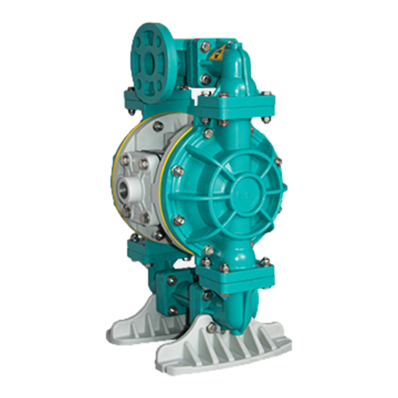
- Page 21 MIT 1500 Technical Information Metal Body Plastic Body 356 146 146 274 191 220 293 312 130 220 480 315 286 356 250 139 218 172 200 265 Packaging Sizes and Weights As it is seen in the following figure, the diaphragm pump is connected to pump fixing board from its stands via bolt and nut.
- Page 22 Spare Part Drawing (Metal) Item Item Description Piece Description Piece Suction Line Gasket, Valve Body Elbow, Suction O-Ring, For Pin Discharge Line Plate, Inner Diaphragm Elbow, Discharge Plate, Outher Diaphragm Manifold Plunger, Actuator Seal, Manifold Srod, Diaphragm Main Body Oil Seal Chamber Outhor Muffler Ball, Check...
- Page 23 Spare Part Drawing (Plastic) Item Item Description Piece Description Piece Suction Line Gasket, Air Discharge Elbow, Suction Gasket, Intermediate Bracket Bracket, Mounting Gasket, Valve Body Discharge Line O-Ring, For Pin Elbow, Discharge Plate, Innet Diaphragm Manifold Cap, Air Inlet Seal, Manifold Plunger, Actuator Main Body Srod, Diaphragm...
- Page 24 MIT 4000 Technical Information Metal Body Plastic Body 605 260 245 425 253 363 505 363 224 253 703 276 269 440 242 368 538 363 180 254 Packaging Sizes and Weights As it is seen in the following figure, the diaphragm pump is connected to pump fixing board from its stands via bolt and nut.
- Page 25 Spare Part Drawing (Metal) Item No Desctription Piece Item No Desctription Piece Suction Line Gasket, Intermediate Bracket Elbow, Suction Gasket, Valve Body Discharge Line O-Ring, For Pin Elbow, Discharge Plate, Inner Diaphragm Manifold Plate, Outher Diaphragm Seal, Manifold Plunger, Actuator Main Body Srod, Diaphragm Gasket, Inner Chamber...
- Page 26 Spare Part Drawing (Plastic) Item No Desctription Piece Item No Desctription Piece Suction Line Gasket, Intermediate Bracket Elbow, Suction Gasket, Valve Body Bracket, Mounting O-Ring, For Pin Discharge Line Plate, Inner Diaphragm Elbow, Discharge Cap, Air Inlet Manifold Plunger, Actuator Seal, Manifold Srod, Diaphragm Main Body...
- Page 27 MIT 5600 Technical Information Metal Body Plastic Body 669 365 299 438 263 418 556 370 223 298 790 294 288 450 288 408 584 370 240 298 Packaging Sizes and Weights As it is seen in the following figure, the diaphragm pump is connected to pump fixing board from its stands via bolt and nut.
- Page 28 Spare Part Drawing (Metal) Item No Desctription Piece Item No Desctription Piece Suction Line Gasket, Air Discharge Elbow, Suction Gasket, Intermediate Bracket Discharge Line Gasket, Valve Body Elbow, Discharge O-Ring, For Pin Manifold Plate, Inner Diaphragm Seal, Manifold Plate, Outher Diaphragm Main Body Plunger, Actuator Gasket, Inner Chamber...
- Page 29 Spare Part Drawing (Plastic) Item No Desctription Piece Item No Desctription Piece Suction Line Gasket, Air Discharge Elbow, Suction Gasket, Intermediate Bracket Bracket, Mounting Gasket, Valve Body Discharge Line O-Ring, For Pin Elbow, Discharge Plate, Inner Diaphragm Manifold Cap, Air Inlet Seal, Manifold Plunger, Actuator Main Body...
- Page 30 MIT 8900 Technical Information Metal Body Plastic Body 858 443 415 504 306 514 735 421 290 995 576 508 594 353 528 794 424 240 404 Packaging Sizes and Weights As it is seen in the following figure, the diaphragm pump is connected to pump fixing board from its stands via bolt and nut.
- Page 31 Spare Part Drawing (Metal) Item No Desctription Piece Item No Desctription Piece Suction Line Gasket, Valve Body Discharge Line O-Ring, For Pin Main Body Plate, Inner Diaphragm Gasket, Inner Chamber Plate, Outher Diaphragm Chamber, Outhor Plunger, Actuator Chamber, Inner Srod, Diaphgram Ball, Check Oil Seal Ball Seat...
- Page 32 Spare Part Drawing (Plastic) Item No Desctription Piece Item No Desctription Piece Suction Line Gasket, Air Discharge Elbow, Suction Gasket, Intermediate Bracket Bracket, Mounting Gasket, Valve Body Discharge Line O-Ring, For Pin Elbow, Discharge Plate, Inner Diaphragm Manifold Cap, Air Inlet Seal, Manifold Plunger, Actuator Main Body...
- Page 33 Otherwise, pump maintenance will be more expensive and difficult. Control bolt connections in each use. Tighten loose connections with a suitable wrench. Replace required connections. Diaphragm Maintenance MIT 160 Main Body Oil Seal Bumper...
-
Page 34: Mit 160
MIT 4000 / MIT 5600 / MIT 8900 Main Body Capscrew Soc Head M10x60 Srod, Diaphragm Oil Seal Bumper Plate, Inner Diaphragm Diaphragm Plate, Outher Diaphragm Double diaphragm is used with options of teflon diaphragm pump. The rubber diaphragm used before the teflon increase the service life of the teflon diaphragm by improving its breakage and fatigue strength. -
Page 35: Mit 1500
MIT 4000 / MIT 5600 / MIT 8900 Remove external diaphragm fastener by turning it counter-clockwise with a 34 socket wrench to remove diaphragm group from diaphragm shaft. One of the diaphragms shall be removed with internal and external diaphragm fastener and the other shall be removed as connected to the shaft. -
Page 36: Mit 5600
Air Valve Repair Kit MIT 160 Air Valve Body Spool, for Air Valve Sleeve, for Air Valve O-Rings, for Air Valve Cap, End Ring, Retaining MIT 550 Air Valve Body Spool, for Air Valve O-Rings, for Air Valve Sleeve, for Air Valve... - Page 37 MIT 4000 / MIT 5600 / MIT 8900 Air Valve Body Plastic Body Spool, for Air Valve O-Rings, for Air Valve Sleeve, for Air Valve Cap, End Ring, Retaining Air Valve Body Metal Body Sleeve, for Air Valve Spool, for Air Valve...
-
Page 38: Pilot Valve Repair Kit Types And Maintenance
Friction Air Valve Spool, for Air Valve Sleeve, for Air Valve Segmented Air Valve Spool, for Air Valve MIT 4000 / MIT 5600 / MIT 8900 Friction Air Valve Segmented Air Valve Sleeve, for Air Valve Sleeve, for Air Valve... - Page 39 Spool, Pilot Valve O-Ring, for Pilot Valve Piston O-Rings, for Pilot Valve Case Sleeve, for Pilot Valve MIT 4000 / MIT 5600 / MIT 8900 Pilot Valve Body Ring Retaining, for Pilot Valve Spool, Pilot Valve O-Ring, for Pilot Valve Piston...
-
Page 40: Actuator Plunger Maintenance
MIT 1500 Main Body Plunger, Actuator O-Ring, For Pin Bushing, Plunger MIT 4000 / MIT 5600 / MIT 8900 Main Body Plunger, Actuator O-Ring, For Pin Bushing, Plunger If the nose pin is damaged while operating under high pressure, and the problem insists when the pin is replaced, replace with a pin with larger cross section. -
Page 41: Plastic And Metallic Body Pump Check Valve Maintenance
Ball surfaces should be placed completely on surfaces of the ball seats. This affects the efficiency of the pump. Replace worn and damaged parts when necessary. Regroup check valve parts. MIT 160 MIT 550 Plastic Body... - Page 42 MIT 1500 Plastic Body Metal Body Elbow, Suction Elbow, Suction Gasket, Ball, Ball Seat Seat Ball Seat Ball, Check Chamber Ball, Check Outher Chamber Elbow, Outher Discharge Elbow, Discharge MIT 4000 Plastic Body Metal Body Elbow, Elbow, Suction Suction Gasket, Ball,...
- Page 43 MIT 5600 Plastic Body Metal Body Elbow, Suction Elbow, Suction Bracket, Ball Seat Mounting Ball Seat Ball, Check Chamber Ball, Check Outher Chamber Elbow, Outher Discharge Elbow, Discharge MIT 8900 Plastic Body Metal Body Elbow, Suction Elbow, Suction Bracket, Ball Seat...
-
Page 44: Problems That May Occur In The Pump And Their Solutions
Compressor air is excessively moist. Clean compressor tank. Torque Line In Plastic and Aluminium Body Pumps Civataları aşağıda belirtilen torklarla sıkınız. Civata sıkma sırasına mutlaka uyulmalıdır. MIT 160 (Plastic Body) Air Valve Cover (6N.m_9N.m) T Elbow Part (6N.m_10N.m) Pilot Valve Cover (6N.m_9N.m) - Page 45 MIT 550 (Plastic Body) Air Valve Cover (8N.m_10N.m) T Elbow Part(8N.m_10N.m) Pilot Valve Cover (10N.m_13N.m) Right Left Fluid Cover (10N.m_13N.m) MIT 550 (Aluminium Body) Air Valve Cover (8N.m_10N.m) T Elbow Part (8N.m_10N.m) Pilot Valve Cover (13N.m_15N.m) Right Left Fluid Cover (13N.m_15N.m)
- Page 46 MIT 1500 (Plastic Body) Air Valve Cover (21N.m_23N.m) T Elbow Part (22N.m_25N.m) Pilot Valve Cover (21N.m_23N.m) Right Left Fluid Cover (19N.m_21N.m) MIT 1500 (Aluminium Body) Air Valve Cover (21N.m_23N.m) Pilot Valve Cover (22N.m_25N.m) T Elbow Part (20N.m_22N.m) Right Left Fluid Cover (20N.m_22N.m)
- Page 47 MIT 4000 (Plastic Body) Air Valve Cover (27N.m_30N.m) Pilot Valve Cover (27N.m_30N.m) T Elbow Part (27N.m_30N.m) Right Left Fluid Cover (29N.m_32N.m) MIT 4000 (Aluminium Body) Pilot Valve Cover (28N.m_31N.m) Air Valve Cover (28N.m_31N.m) T Elbow Part (28N.m_31N.m) Right Left Fluid Cover (29N.m_33N.m)
- Page 48 MIT 5600 (Plastic Body) Air Valve Cover (28N.m_31N.m) Pilot Valve Cover (28N.m_31N.m) T Elbow Part (28N.m_31N.m) Right Left Fluid Cover (29N.m_32N.m) MIT 5600 (Aluminium Body) Air Valve Cover (28N.m_31N.m) Pilot Valve Cover (28N.m_31N.m) T Elbow Part (28N.m_31N.m) Right Left Fluid Cover (30N.m_33N.m)
- Page 49 MIT 8900 (Plastic Body) Pilot Valve Cover (27N.m_30N.m) Air Valve Cover (27N.m_30N.m) T Elbow Part (27N.m_30N.m) Right Left Fluid Cover (28N.m_30N.m) MIT 8900 (Aluminium Body) Air Valve Cover (28N.m_32N.m) Pilot Valve Cover (28N.m_32N.m) T Elbow Part (28N.m_32N.m) Right Left Fluid Cover (28N.m_32N.m)
-
Page 50: Warranty
MIT brand that it produces are sold to Equipment shall be returned to final user final user. This warranty applies only when the as prepaid transportation fee. If there is no... - Page 51 conflict, consumer has liability to prove. 5 years: Ekin Endüstriyel gives warranty on spare part and labor supply. 5 -10 years: Ekin Endüstriyel gives only warranty on supplying spare part. All written and visual data in this document reflect last product information current while they were printed.
- Page 52 CERTIFICATES...
- Page 54 PROFESSIONAL SYSTEM SOLUTION CENTER From our MIT professional system solution center, you can get help with your problems with your pumps, heat exchangers and your system. Our solution center consisting of expert mechanical engineers will be happy to help you.
- Page 56 EKİN 3 5 4 6 Isıtma-Soğutma San. Tic. Ltd. Şti. Dudullu Organize Sanayi Bölgesi - Des Sanayi Sitesi 107. Sk. B14 Blok No: 2 Ümraniye / İstanbul / Turkey Phone: +90 216 232 24 12 Fax: +90 216 660 13 08 info@ekinendustriyel - www.ekinendustriyel.com...
Need help?
Do you have a question about the 1500 and is the answer not in the manual?
Questions and answers