Table of Contents
Advertisement
MOTION CONTROL SYSTEMS
HARDWARE INSTRUCTION MANUAL
STEPPING MOTOR DRIVES
CSD ET 04 - CSD ET 94
R.T.A. s.r.l.
R.T.A.
DEUTSCHLAND GmbH
R.T.A. IBERICA
MOTION CONTROL SYSTEMS S.L.
SERIES
R.T.A. s.r.l. – CSETME06 – 09/21
Via E. Mattei – Frazione DIVISA
27020 MARCIGNAGO (PV)
Tel. +39.0382.929.855 - Fax +39.0382.929.150
Internet: http://www.rta.it - e-mail: info@rta.it
Bublitzer Straße, 34
40599 DÜSSELDORF (Germany)
Tel. +49.211.749.668.60-Fax +49.211.749.668.66
Internet: http://www.rta-deutschland.de
e-mail: info@rta-deutschland.de
C/Generalitat 22, 1° 3°
08850 GAVA – BARCELONA (Spain)
Tel. +34.936.388.805-Fax +34.936.334.595
Internet: http://www.rta-iberica.es
e-mail: info@rta-iberica.es
Advertisement
Table of Contents

Related Manuals for RTA CSD ET 94 Series


Summarization of Contents
Notices and Manual Structure
Manual Scope and Terms Definition
Defines the manual's coverage of CSD ET series drives and key terminology.
Product Standards Compliance
Lists standards and directives the CSD ET series drives comply with.
Limitations, Hazards, and Cautions
Motor Terminal and Usage Restrictions
Specifies allowed motor terminal configurations and prohibited usage of the drives.
Environmental and Protection Requirements
Details IP20 rating, operating temperature, and pollution degree requirements.
Stored Energy and Safety Precautions
Warns about residual voltage in capacitors and necessary waiting times after power off.
Thermal and Environmental Hazards
Advises caution regarding hot heatsinks and flammable environments.
Assembler Responsibility and Safety Systems
Clarifies designer responsibility and the need for external safety systems.
Failure Voltage and Protection Limitations
Discusses potential high voltage on terminals during failure and limitations of internal protection.
General Characteristics and Identification
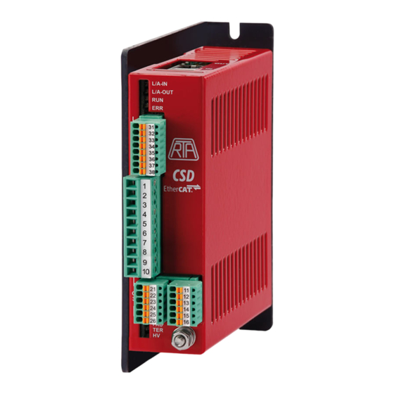
Drive Dimensions and Physical Layout
Provides physical dimensions and connector pinouts for the CSD ET series drives.
Model and Serial Number Identification
Explains the naming convention and identification codes for CSD ET series models.
Input and Output Logic Signals
Input Signal Specifications (C3 Connector)
Details voltage requirements and pin assignments for digital inputs on connector C3.
Output Signal Specifications (C3 Connector)
Describes available outputs, current ratings, and pin assignments on connector C3.
Encoder Inputs and Power Supply (C1 Connector)
Outlines pin assignments and specifications for encoder connections via C1.
EtherCAT Communication Ports (RJ-45)
Details the RJ-45 connectors for EtherCAT communication and their pinout.
Inputs and Outputs Power Lines
Connector C2 Power Line Assignments
Lists the terminals for motor windings, logic supply, and power supply on connector C2.
Earth and Grounding Connections
Explains the grounding requirements and connections for the drive system.
Power Input/Output Characteristics and Definitions
Presents technical specifications and defines key terms for power lines.
Drive Setting and Alert Signals
Drive Configuration and LED Indicators
Introduces drive settings and the function of status LEDs on the drive casing.
EtherCAT Connector Layout
Illustrates the physical location of EtherCAT connectors on the drive's high side.
Alert LED Status Meanings
Details the conditions that trigger the green (HV) and yellow (TER) alert LEDs.
EtherCAT Communication LED Status
Explains the status indicators for EtherCAT ports and the RUN/ERR LEDs.
Drive External Connections
External Component Design Considerations
Guides the selection of transformer, rectifier, and capacitor for the power supply.
Transformer Requirements for Isolation
Specifies voltage, galvanic isolation, and dedicated use requirements for transformers.
Fuse Specifications and Capacitor Calculation
Provides fuse types, branch circuit protection, and capacitor value calculation methods.
Conductor Sizing and Shielding
Advises on selecting conductor cross-sections and motor cable shielding.
Installation and Environment Limits
IP20 Enclosure and Direct Connection Prohibition
Stipulates the need for an enclosure and forbids direct mains connection.
Installation Environment Conditions
Defines acceptable temperature, humidity, and pollution degree for installation.
Storage Environment Limits
Specifies temperature and humidity ranges for storing the drive in its original packaging.
Heat Dissipation and Mounting Advice
Provides guidance on drive mounting for optimal heat dissipation and airflow.
Application Notes
Power Supply Usage Restriction
Prohibits using the drive's power supply for other machines.
Electromagnetic Compatibility (EMC) Measures
Details methods to reduce electromagnetic interference from drives and motors.
Installation Compliance and Testing
Emphasizes compliance with EMC directives and the role of installation testing.
Grounding Conflicts and Safety Priority
Addresses potential conflicts between safety and shielding grounds, prioritizing safety.
Need help?
Do you have a question about the CSD ET 94 Series and is the answer not in the manual?
Questions and answers