Advertisement
Table of Contents
- 1 Table of Contents
- 2 Safety and Regulations
- 3 Introduction
- 4 LUBA Quick Start Installation
- 5 Preparation & Activation
- 6 Basic Operation & App Interface Introduction on Main Page
- 7 Basic Operation & App Interface Introduction on Map Page
- 8 Create a Task
- 9 Parameter & Schedule Setting and Start Task
- 10 Cutting Blades Replacement
- 11 Specifications
- 12 After-Sales Policy
- 13 Maintenance Guide
- 14 Disclaimer
- Download this manual
Advertisement
Table of Contents

Related Manuals for AMMOTION LUBA AWD3000


Summary of Contents for AMMOTION LUBA AWD3000
- Page 1 LUBA Robotic Lawn Mower AWD5000&3000 User Manual V1.2...
-
Page 2: Table Of Contents
Catalogue 1. Safety and Regulations 2. Introduction 3. LUBA Quick Start Installation 4. Preparation & Activation 5. Basic operation & App interface introduction on main page 6. Basic operation & App interface introduction on Map page 7. Create a task 8. -
Page 3: Safety And Regulations
1. Safety and Regulations Operating MAMMOTION LUBA requests training and practice. Please read through this document before operating it in your garden. Do NOT charge the LUBA with third-party charger. Do NOT flip over the mower when it’s running. Do NOT put your feet / hands under the mower when it’s running. Do NOT push/pull the mower when it’s running. -
Page 4: Introduction
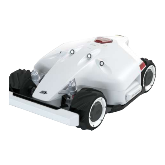
2.Introduction 2.1 About MAMMOTION LUBA MAMMOTION LUBA is a 4-wheels-differential (4WD) robotic lawn mower. The 4WD enables LUBA to break the limits of mowing jobs. LUBA Series robot lawnmowers feature RTK GNSS navigation and virtual-mapping systems. These allow users to customize their mowing tasks with different mowing areas and schedules on Mammotion APP. They provide a picture-perfect lawn maintenance solution with a real hands-free experience. - Page 5 2.3 LUBA Robotic Mower E-stop Cutting button Protecting bracket Start button Ultrasonic sensor Front bumper Power button Left light Connecting indicator Auto-return button Side collision sensor Rain sensor Secure key USB port Infrared sensor SIM port(Reserved*1) Charging port Note:The reserved port might not function in some previous version mowers.
- Page 6 Cutting blade*8 Blade disk*2 Function Buttons Long press (5s) Power on/off LUBA Press Stop and lock LUBA First press then press Unlock LUBA and continue work Unlock LUBA and return First press then press to charging station...
- Page 7 LUBA lighting logic LED indicator on the Status LED side light front bumper LUBA sleeping or "Pause" Green on on App clicked From local time 8:00-18:00 green on Working (manual control and from local time 18:00-8 00 off Green on automatic working) user can manully switch it off Upgrading...
- Page 8 2.4 Charging Station Mounting hole for RTK reference staion pole Screw*5 Mounting hole*5 Charging station power supply Charging pin on charging station Charging station extension cable(10m) LED light of charging station Charging Station lighting logic Status LED on charging station Light on adapter Charging Flashing green...
- Page 9 2.5 RTK Reference Station Radio Antenna RTK Reference Station RTK reference station and charging station connect cable(1.8m) RTK Reference Station lighting logic Status LED on RTK reference station Reference station initializing green flash (searching satellites) from local time 8:00-18:00 green constant on from Work properly local time 18:00-8:00 off Reference station defect &...
- Page 10 2.6 Other accessories: LUBA garage: LUBA RTK reference station L-shaped mounting rod wall installation kit: You can purchase these accessories on the official website.
- Page 11 2.7 How LUBA’s positioning and dynamic system works: LUBA use RTK and Multi-Sensor Integrated Navigation System to navigate. RTK is a satellite navigation system that significantly improves device positioning to accuracy less than 5cm. With access to all 4 global navigation systems (GPS, GLONASS, BEIDOU and Galileo) and additional sensors, LUBA’s strong satellite signal provides nearly 100x greater accuracy compared to traditional GPS systems.
- Page 12 In general, there are 3 factors that can weaken the performance of LUBA positioning system: Factor 1: Satellite signal from RTK Reference station Blocking: If there is anything on or surrounding the antenna of RTK reference station, charging station and/or the mower, the signal will be weakened or blocked.
- Page 13 Factor 3: Transmission path obstruction If the transmission path from RTK Reference Station and LUBA is fully obstructed by large metal wall or concrete wall. LUBA will not get the data from RTK Reference station and will not get the required 15cm level accuracy.
- Page 14 About Multi-Sensor Integrated Navigation System: The Multi-Sensor Integrated Navigation System is mainly to enhance the reliability and robustness LUBA’s positioning status. This system contains IMU, odometer and other sensors. Even in the partly sheltered area, thanks to the strong positioning algorithm, LUBA can work correctly. About Auto-Recharging:...
- Page 15 1.Place the LUBA about 1.5m-2m in front of the charging station and the bottom of LUBA aligned to the charging station. 2.Press power button of LUBA to power LUBA on. Pressing then press to let LUBA back to charging station. You can also charge the LUBA indoors, you do not have to have satellite signal, but the LUBA will not operate indoors.
-
Page 16: Luba Quick Start Installation
Status Ultrasonic sensors Front bumper Area of application Should be only used in areas where the Once triggered, LUBA will grass is nearly all high higher than 15cm go backwards,thenturn which can lead to nearly constant disturb and bypass the obstacle to ultrasonic sensors Useful for lawn, which is partly with high Level 1... - Page 17 Or install RTK Reference station on the wall or roof with open sky area. As shown below. ≥ 90。 2. At least 5m away from large glass wall or large metal objects such as wall made of iron sheet. 3. The RTK Reference station should be set straight as shown below: 4.
- Page 18 Correct RTK reference station settings: 1.Open sky area on the lawn (at least 3m from the wall). 2.Set on the roof or wall with open sky area (typically for lawn with “O”-shape, “U” shape, or with sepa- rate lawns). 3.Away from metal walls and glass walls. Wrong RTK reference station settings:...
- Page 19 4.In the middle of several obstacles like 2 walls, a wall, and a tree etc.). 5.Keep separate from the lawn. 6.Too far away (more than 80m) from edge of lawn. 3.2 Find a Good Place to set Charging Station As shown in chapter 2.2 “About Auto-Recharging”, the charging station should be set to a place where: 1.
- Page 20 Correct charging station settings: The place to set charging station should be flat and solid ground, also the “recharging area” (about 2m front charging station) should be on flat and solid ground, where the grass is short. F l a t G r o u Wrong charging station settings: 1.Do not set up charging station on a slope.
- Page 21 3.3 The RTK base is installed on the charging station If the reference station is set on charging station, then this should be set as follows: Correct settings: 1. Open sky area. 2. One side beside the wall and only one direction is within wall, other directions must be totally free. Overview of the installation when it’s completed:...
- Page 22 Installation Kit: Charging station extension cable(10m) RTK reference station Installation Kits Power Supply connect cable(1.8m) RTK Reference Station Accessory Kit A Accessory Kit B Charging Station RTK reference station power supply Trident Ground Stake RTK reference station extension cable(10m) Bumper Accessory Kit C RTK Wall Mount Accessory Kit: Mounting pole...
- Page 23 2.Screw the Charging station extension cable(10m)into the interface C of the charging station. 3.As shown in the figure, twist two metal rods into one metal poles, then twist trident ground stake with the metal pole. 4.Fix the charging station on a flat solid ground with fixing screws. Insert and fix the trident ground stake as shown in the figure and keep the metal pole upright.
- Page 24 6.Connect RTK reference station connect cable (1.8m) with RTK antenna reference station cable. 7.Connect the Charging station extension cable(10m) with power plug,and connect the power plug to the electrical outlet. 8.Check if the LED on the charging station is green. If it turns green, then right. If it turns red, please pull out the power plug and re-do the charge.
- Page 25 Wrong settings: Overview of the installation when it’s completed. RTK Wall Mount Kit: RTK Wall Mount RTK reference station RTK reference station Accessory power supply extension cable(10m) Installation Process: 1. Choose a suitable installation area at a high place of your house. 2.
- Page 26 3.Install the expansion screws in the drilled holes. 4.Fix the RTK Reference Station on the sticker and tighten the screws. 5.Connect the end of the RTK Reference Station extension cable (10m) to the RTK reference station and connect the other end of the RTK Reference Station extension cable (10m) to the RTK power supply and turn on the power.
- Page 27 6.The installation is complete. 3.5 LUBA RTK reference station L-shaped mounting rod wall installation instruction Products include: L-shaped mounting rod Expansion screw*4 Drilling position in dication sticker Cable buckle*3 Installation Notes:...
- Page 28 Correct settings: ≥ 90。 ≥ 90。 Install on wall,in open area. Install on roof far from any obstruction that may affect signal. Wrong settings: Do NOT install antenna surrounded by Do NOT install on high wall. walls or in covered areas. Do NOT install under eaves or gutters.
- Page 29 Installation Process: 1. Choose a suitable installation area on the outer wall of your house. 2. Stick the sticker on the wall indicating the position of the drilling hole and drill the hole at the appropriate position. 3.Install the expansion screw in the drilled hole. 4.
- Page 30 5. Install the RTK reference station on the front end of the L-shaped installation pole (note that the antenna must be installed on the RTK reference station first). 6. Connect the end of the RTK Reference Station extension cable (10m) to the RTK reference station and fix the cable harness along the L-shaped installation rod with a cable tie.
- Page 31 3.6 LUBA garage installation Installation Notes: Fasten the garage cover on the top of the charging station from front to back and tighten the two screws on the back of the garage cover to complete the installation of the garage. Precautions: 1.Do not place items on the top of the garage to avoid damage to the garage and affect the vehicle signal.
-
Page 32: Preparation & Activation
4. Preparation & Activation 4.1 MAMMOTION APP download & Installations MAMMOTION LUBA is a 4-wheels-differential (4WD) robotic lawn mower. The 4WDenables LUBA to break the limits of mowing jobs. LUBA Series robot lawnmowers feature RTK GNSS navigation and virtual-mapping systems. These allow users to customize their mowing tasks with different mowing areas and schedules on Mammotion APP. - Page 33 4.2 MAMMOTION account sign up and login How to sign up: 1.Switch on the Position and Bluetooth on your phone. Click Sign up and select the country and input your email address. 2.Then click “Send verification” .A verification code will be sent to your email (if you don’t receive the verify code, please check your spam folder or check the blacklist of your Email and wait several minutes and retry to click the Code).
- Page 34 How to login: 1.Input your account and password to login. 4.3 Add your LUBA to Mammotion App, setup and self-checking: After users login the App for the first time, it needs to Add device to it. Note: 1. Please read the guide on Mammotion App carefully; 2.
- Page 35 Loading If it shows “ ”, please wait a moment. One LUBA can be connected to ONLY ONE Mammotion account. One Mammotion account can add multiple LUBAs. Different phones can use the same Mammotion account. Only one phone can control one LUBA at the same time.
- Page 36 4.Add LUBA to Mammotion account. Activate LUBA: After the Bluetooth connection, it needs to connect LUBA to Wi-Fi & Hot spot for activa- tion. Note: The connection is between LUBA and MAMMOTION Cloud, it has nothing to do with how your phone connect to the Internet, which means you do not have to connect your phone to the same WIFI &...
- Page 37 5. Self-checking: After the initialization for the 1st time you use LUBA, the whole system should be: RTK reference station at proper place. Charging station at proper place. LUBA is on the charging station and the charging process should be OK and stable. LUBA should be switched on.
- Page 38 4.3 Basic operation & App interface introduction on main page The main page is as shown below: Settings: Unbound: Unbound the added LUBA. Firmware version: Check the version of the Firmware of different parts on LUBA. Upgrade: Upgrade the Firmware, if there is a red dot, means you have new firmware and can do the upgrade.
-
Page 39: Basic Operation & App Interface Introduction On Main Page
5.Basic operation & App interface introduction on main page 5.1 Firmware upgrading: Preparation: 1.Please make sure that your LUBA is powered on (with the LED on the front bumper green;). 2.Make sure the distance between your phone and LUBA is less than 3m. 3.Make sure that there is good stable WI-FI or GPS signal. - Page 40 2. To start upgrading: click “Upgrade” button in the settings or the symbol to start upgrading. 3.The message box will show you what is new in the firmware. Click “One click upgrade” 4.Wait until the upgrading is done (make sure the WIFI & Hotspot is available during the upgrade).
- Page 41 5.When the APP shows that LUBA is successfully upgraded, the LUBA will automatically switch off, please LONG Press for about 10s until the LED side lights is on. 6.If the upgrade failed, please check the WIFI & Hotspot connection and try again. 7.Check if the firmware of LUBA and APP have already reached the newest firmware by clicking “setting version”.
- Page 42 5.2 How to check firmware version and App version: Check firmware version: Check App version: 5.3 Issue & Log feedback Important information about how to provide feedback: 1.Please describe HOW the issue is, WHEN and WHERE the issue appears.It will help us a lot to fix the issue.
-
Page 43: Basic Operation & App Interface Introduction On Map Page
Feedback process: Note: 1.During the feedback process, please make sure that both the Bluetooth and WIFI & Hotspot connec- tion is good. And the distance between your phone and LUBA is less than 3m. 6.Basic operation & App interface introduction on Map page Below is the interface of map&control page:... - Page 44 1. Back to previous page: to main page 2. LUBA status. The status are as follows: STATUS charging connection path planning paused returning initializing obstacle planning working ready lock task planning offline 3. Device number 4. Guide message box 5. Mower battery power 6.
- Page 45 Click the “POS” symbol will show more detailed information about positioning status. As shown below: Bluetooth quality: show the strength of Bluetooth connection. Number of satellites: The Number of satellites observed by LUBA. If either of the 2 numbers is under 20, there will be risk that the positioning status may be “unavailable”.
- Page 46 Positioning meaning accuracy reason to do status no satellite signal received at all Drive LUBA/set task area to a more positioning ( in the room/ LUBA covered/ defect) open sky area. single point Several LUBA does not received RTK 1. check if the LED on RTK positioning meters reference station at all,(please...
- Page 47 6.Fill any large holes in your lawn. 7.When LUBA is working, make sure that there is no person, children, pets or other moving things in your lawn. 8.We highly recommend you set the area with no obvious holes, gullies, roots of the trees or other obstacles in the no-go zone.
- Page 48 Note: if “Done” clicked, means that a task area will be created immediately, one boundary will be from the start point to LUBA’s current location. If in the image, the “Done” is clicked, a triangle task area will be created. Another way to finish task creating is that manually drive LUBA back to the task area start point.
- Page 49 28. Working route (at boundary) 29. Working route 30. Recharging area 31. More 32. Pause (when LUBA is working automatically) 33. Estimated task time (charging time not included) 34. Task area 35. End task (go back to charging station, the task will not continue, when LUBA is 95% charged) 36.
-
Page 50: Create A Task
7.Create a task Note: 1.Remove debris, piles of leaves, toys, wires, stones, and other obstacles. Make sure children and pets are on the lawn. 2.We highly recommend you leave 10-15cm distance if you drive LUBA along the edge of a wall / fence / obstacles / hedges. - Page 51 5.After the initialization, LUBA’s status turn to “Ready” now you can start creating a task! As shown below. Note: 1. If both the charging station & RTK reference station are not moved, next time you restart LUBA (like over a winter) or add / change / delete the task area, you do not need to re-do the initialization. As long as LUBA’s status is “Ready”, it can continue working.
- Page 52 7.2 Create a task map: 1. click “Create” to start creating task map. 2. Read the guidelines of creating task & working with LUBA 3.Start drawing the task area boundary.
- Page 53 Note: 1) if “Done” clicked, means that a task area will be created immediately, one boundary will be from the start point to LUBA’s current location. if in the image, the “Done” is clicked, a triangle task area will be created.
- Page 54 4.Finish the boundary drawing of 1 task area. 5.You can continue planning (add another task area in the same task, add no-go zone, add connection path)
- Page 55 Note: You need to first drive LUBA into a already existed task area to create a connection path and no go zone, because they(or part of them) should be in the task area. You need to first drive LUBA out of the already existed task area to create a new task area. If task 2 area overlapped.
- Page 56 7.3 Edit the task map 1.Click “Edit” to edit the task map, currently, you can only add areas, no-go zones, connection path in the already existed task map, you cannot delete and change the boundary or path, but we are working on that function.
-
Page 57: Parameter & Schedule Setting And Start Task
4.If any unexpected issue occurs, press the STOP button and lock LUBA. The STOP button has the high- est priority. 5. If the lift sensor is triggered, LUBA will stop, please press grass cutting button and then start button to unlock LUBA. - Page 58 8.3 Schedule settings 1. Select the area you want to set the schedule 2.Set the date in each week and the start time of the selected date you want LUBA to work. 3.For the first time you use LUBA, we highly recommend you set the cutting height higher than 50mm.
-
Page 59: Cutting Blades Replacement
4.The schedule of each task will be shown in the schedule sheet. 9.Cutting blades replacement The cutting blades can be replaced when they are damaged or worn out. We recommend you change the blades every 6 month. Tools needed:M2.5 Allen Key. The LUBA MUST BE TURNED OFF when replacing, inspecting or cleaning the cutting blades. -
Page 60: Specifications
10. Specifications: specification LUBA AWD 5000 LUBA AWD 3000 LUBA AIR 1000 Lawn Size Up to 5000m² Up to 3000m² Up to 1000m² Engine All-Wheel Drive (AWD) All-Wheel Drive (AWD) Rear-Wheel Drive (AWD) Max Climbing Ability 75% slope 65% slope 45% slope Vertical Obstacle Passing Ability 50 mm... -
Page 61: After-Sales Policy
11. After-sales Policy: 11.1 Cuetomer services flow Issue Report Note: 1. SN is on the sticker on machine body. For example, ***-2238****-S/N. Information Gathering 2. Service Center Contact Information: 1. Product’s SN *1 2. Purchasing invoice or receipt attached Contact support@mammotion.com for 3. - Page 62 11.2 Part I - limted Warranty These MAMMOTION After-Sales Policies (these “Policies”) only apply to MAMMOTION products you purchased from MAMMOTION authorized retailers or MAMMOTION directly for your own use and not for resale. By using your MAMMOTION product, you agree to be bound by these Policies. If you are not eligible or do not agree to any of the Terms, do not use your MAMMOTION product.
- Page 63 1.The warranty period for a product starts on the day such products are delivered. 2.If you cannot provide invoice or other valid proof of purchase, then the warranty period will start from 90 days after the production date that shows on the product, unless otherwise agreed upon between you and MAMMOTION.
- Page 64 Table for parts warranty: Model LUBA Component Limited warranty period Main body 2 years Battery 2 years Accessories Charging station &RTK antenna 1 years Type No warranty Wearing parts Decoration/Appearance parts No warranty Cutting blade No warranty *MAMMOTION reserves the rights of interpretation for this Limited Warranty and may not be able to notify each user when updates happen.
-
Page 65: Maintenance Guide
12.Maintenance Guide In order to have your LUBA in a good condition at all times, please clean your LUBA each time after mowing. The cleaning process in MAMMOTION user manual instructs you to get rid of the clippings, twigs, leaves or dust and keep the mower in good condition. 1.Motors and cutting blades maintenance (After Every Mowing task) 1.1 Turn off the mower and flip it over on a relatively soft surface ground. - Page 66 8.Damage caused by operating the product in an environment with electromagnetic interference (i.e., in mining areas or close to radio transmission towers, high-voltage wires, substations, etc.). 9.Damage caused by operating the product in an environment suffering from interference from other wireless devices (i.e., transmitter, video-downlink, Wi-Fi signals, etc.).
Need help?
Do you have a question about the LUBA AWD3000 and is the answer not in the manual?
Questions and answers